
CG Envelope
How far forward and how far aft the CG can sit, and where that puts the pack. The forward limit comes from the elevons: at low speed they must still have up travel left after trim. The aft limit comes from the static margin. This page first describes the first build, Fuselage C v2.4B with our wing and its fence (2026-10-19). The analysis of the earlier wing, which set the 265 to 270 mm band and the slider, follows it unchanged for its reasoning.
The short version: the first build weighs about 3,025 g with its nose trim bracket, and balances at 268 mm with the pack’s front at Y 75.6, 1.6 mm aft of the CG slider’s forward stop, with no trim washers. The envelope runs from about 249 mm (the elevons run out at the trimmed stall) to 270 mm (the agreed hard aft edge, with about 6 % static margin in the band where the earlier wing went soft), with 8.5° of up elevon in hand at the stall at 268. The balance band’s forward edge is the CG the stall test flies, since nothing should fly forward of a tested CG: 265 mm on the earlier wing. On C the stall test aims at 266 mm and must measure at or forward of 267, and the band’s forward edge follows it, so the band is 267 to 270 mm, since every accepted test measures at or forward of 267 (Ryan, 2026-10-19, with the trim row); the aim stays 268, and in practice C never flies forward of about 268. Weigh and balance before the maiden flight: the slider has no forward travel left, so any tail-heavy error is met with trim weight at the nose.
The first build: Fuselage C v2.4B
Section titled “The first build: Fuselage C v2.4B”Mass and CG. The build-up is th-blender’s W78 table of sourced groups (bed grams by part volume, the parts list’s vendor masses, the measured lead runs), reconciled on 2026-10-18: the support and purge material on five beds comes out at each part’s own centroid, the PM02 is 20 g, the carbon spars are estimated at 1.55 g/cm3, and changes promoted since the draft are added (the side tube, W93.2; the nose trim bracket, W100.1; the open-mouth tube and the tilted camera’s nose, W104; the blank payload cover in ASA, th-main ac479f25) (tools/cg_c24b.py, aero/cg/c24b.json; Ryan accepted the 3.04 kg on 2026-10-18). The reconciliation moved the CG by under 0.1 mm: the supports came out mostly at the rear keel mounts, and the added spar mass, mostly the wing spars, put almost all of it back. The pack, its slider plate and, at night, the light battery ride the slider, whose travel on v2.4B is a pack front of Y 74 to 90 (80 to 96 in the slider generator’s own frame):
| Build | Mass | CG, pack at the forward stop (Y 74) | CG, pack at the aft stop (Y 90) | Pack front for 268 mm | Stall test: washers for 267 mm |
|---|---|---|---|---|---|
| Day (no payload) | 3,024.8 g | 267.5 mm | 272.4 mm | Y 75.6 | 4 (266.98 mm) |
| Day with the Survey3W | 3,154.5 g | 272.8 mm | 277.6 mm | beyond the stop: about 69 g of trim | beyond the row |
| Night (the lights fitted) | 3,197.6 g | 267.4 mm | 272.4 mm | Y 75.9 | 4 (266.88 mm) |
Each millimetre of pack moves the CG about 0.31 mm. The washers are M3 brass fender washers, 15 x 3.2 x 1.5 mm, about 2.15 g each, on the trim bracket at the Front’s port chine (W100.1, 2ae77187), stacking aft from Y 79; the full row of 14 brings the day build to about 266.1 mm with the pack at the forward stop. About 16.9 g of washer moves the CG 1 mm there. The Survey3W’s trim figure is at the Camera Arm (Y 46), about 13.7 g a millimetre, for comparison. All of these are estimates until the balance. The spars are the largest single unknown, about ±15 g.
The day build’s forward margin is small. The side tube’s promotion (W93.2, 60f05e70, about 4 g off the nose at Y 50) moved the CG about 0.3 mm aft and left 268 just past the forward stop; the trim bracket’s own 2.34 g at Y 76 moved it back about 0.15 mm, so 268 became reachable again; then the blank payload cover in ASA (7.8 g lighter at Y 428, th-main ac479f25, 2026-10-21) moved it about 0.4 mm forward, so 268 now sits with the pack 1.6 mm off the stop. Any tail-heavy error on the real aircraft beyond that is met with washers on the row rather than by the slider. The stall test uses the row: 4 washers for 267 mm on the day build and at night, and 12 reach the 266 mm aim (265.95); the weigh-in, not this table, sets the count. The aft stop is beyond the 270 mm hard edge on every build, so the stop pin and CGS_CRUISE_MM (below) keep the pack inside it, as before.
The Survey3W adds 122 g at the belly bay, aft of the CG, and no slider position balances it; with the 69 g of trim it needs, the build is about 3.22 kg; that is beyond the trim row’s 30 g, so the Survey3W is not flyable on C as built, and its return would be a new configuration with its own trim provision. The heaviest configuration C flies today is the night build, 3,197.6 g, which is the mass the stall speed is referred to. Whether it returns is Ryan’s decision.
Envelope. The lift and pitch lines are the C CFD’s (aero/wing-own/c24b-model-inputs.json, coarse shape pinned to the fine run at alpha 6.7), the elevon pair is scaled to the fine run, and the stall is the fenced wing’s trimmed maximum lift coefficient, 0.632 (ESTIMATE):
- Neutral point 294.3 mm from the linear lines, so 268 mm flies at 11.6 % static margin in the cruise range, and a 5 % margin would allow 283 mm.
- The fence keeps most of the stiffness through the band where the earlier wing went soft, and turns the stall break nose-down. About 270 mm, dCm/dCL is -0.061 from alpha 6.7 to 9.5° and -0.060 from 9.5 to 12.5° (e21bcc84; coarse secants), then -0.40 from 12.5 to 14°. Those coarse secants span 3° each; across them the static margin is 7.9 % at 266 mm and 6.1 % at 270. The governing figure is the fine half degree below, where the margin is least: 5.3 % at 267 mm and 4.0 % at 270, against the earlier wing’s about 2 % at 265 to 266 and none at 270. So 270 mm stays the hard aft edge with margin in hand. Fine runs half a degree apart (the W108 re-baseline, 2026-10-19,
aero/wing-own/cfd-rebaseline-w108.json) show that C does soften in the same half degree as the earlier wing, but much less: dCm/dCL is -0.111 from 6.7 to 9.5° and -0.040 ± 0.013 from 9.5 to 10°, against the earlier wing’s 0.000. That leaves 5.3 % static margin at 267 mm and 4.0 % at 270 (4.0 and 2.6 % at the soft end of the uncertainty). The flow there is also unsteady, with the pitching moment fluctuating about 40 times more than at 6.7°: the light, less stable pitch feel the stall card warns of is real on C, only milder. - Forward, the elevons have to hold the trimmed stall. With 25° of travel,
MIXING_GAIN0.75 and the servo trim at the cruise trim for that CG, the up elevon available is about 20°. At 268 mm the stall needs 11.5°, leaving 8.5°. The two meet at about 249 mm, and a 3° cushion puts the limit at about 255 mm. AtAIRSPEED_MIN18 m/s indicated (21 m/s true) the wing needs only 6.9° at 268 mm; that is no longer the binding case, because the stall test and a gust fly well below it.
The 265 mm stall test therefore has 7.2° in hand at the break (12.9° needed), against the earlier wing’s 1.2°.
Trim. This is the table to set the elevon trim from. The speeds are what the flight controller reads on the side static ports at ARSPD_RATIO 2.3, which is about 15 % under the true speed in cruise (the true equivalent airspeed at 268 mm is in brackets). The mass is 3.034 kg, as the c24b-w78 SITL model flies it (tools/c24b_level.py, aero/wing-own/c24b-level.json, 2026-10-19; ESTIMATE). Our wing needs much less up elevon than the earlier wing, and at 22 m/s indicated the cruise trim is about 4.8° trailing edge up at 268 mm:
| CG | 250 mm | 262 mm | 265 mm | 268 mm | 270 mm | 275 mm | 290 mm |
|---|---|---|---|---|---|---|---|
| Up elevon to trim at 18 m/s indicated (21.0 true) | 12.5° | 8.8° | 7.8° | 6.9° | 6.3° | 4.8° | -0.1° |
| Up elevon to trim at 20 m/s indicated (22.6 true) | 10.4° | 7.3° | 6.5° | 5.8° | 5.2° | 3.9° | -0.3° |
| Up elevon to trim at 22 m/s indicated (24.3 true) | 8.8° | 6.2° | 5.5° | 4.8° | 4.3° | 3.2° | -0.5° |
The earlier wing (2026-09-26 to 2026-10-18)
Section titled “The earlier wing (2026-09-26 to 2026-10-18)”Everything below is the analysis of the earlier wing at 2.85 kg on the ideal airspeed sensor, kept for its reasoning: the 265 to 270 mm balance band, the slider and its cruise rule came from it. Its numbers do not apply to the first build.
Since 2026-09-29 both of its limits came from the whole-aircraft CFD: the lift and pitch lines from alpha 4 to 8 of the single-mesh fine sweep, and the elevon pair at ±10° (aero/cfd/results.json). They replace the VSPAERO elevon tables, whose zero-lift terms and elevon slopes did not converge with the mesh, and whose elevon was about 25 % too strong in pitch. First analysed 2026-09-26 for 2.0, 2.25 and 2.5 kg.
Its short version: with ArduPilot’s default elevon mixing there is no CG that satisfies both limits. With 25° of elevon travel and MIXING_GAIN 0.75 the envelope is 258 to 283 mm aft of the nose datum at 2.85 kg, the first build as it flies (CFD, with the elevons trimmed for cruise, 2026-10-06; 256 to 283 at 2.75 kg from 2026-10-01, 254 to 283 at 2.59 kg before). The estimated mass build-up puts the CG at about 291 mm with the pack on its tray, which is at the neutral point. Move the pack and the pusher ESC forward, expect 50 to 130 g at the nose, and weigh and balance before the maiden flight.
The limits
Section titled “The limits”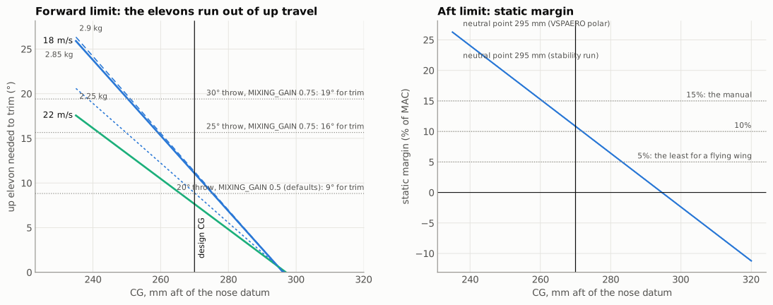
Forward limit (earlier wing, 2026-09-29 analysis). The further forward the CG, the more up elevon the wing needs to trim, and the slower it flies the more still. At 18 m/s (AIRSPEED_MIN, decided 2026-09-27) and 2.85 kg, the first build, from the CFD (2026-09-29; at 2.75 kg until 2026-10-06, 2.59 kg until 2026-10-01):
| CG | 250 mm | 262 mm | 270 mm | 275 mm | 290 mm |
|---|---|---|---|---|---|
| Up elevon to trim at 18 m/s | 19.6° | 14.5° | 11.1° | 9.0° | 2.6° |
| Up elevon to trim at 20 m/s | 16.0° | 11.9° | 9.1° | 7.4° | 2.2° |
| Up elevon at 18 m/s, VSPAERO (until 2026-09-29) | 14.1° | 10.3° | 7.8° | 6.3° | 1.6° |
That travel has to come out of what ArduPilot gives the pitch axis. An elevon is shared between pitch and roll, and MIXING_GAIN sets the share: ArduPlane mixes each elevon as (elevator ± aileron) × MIXING_GAIN about its servo trim, clipped at the servo end. The airframe files set the servo trim to the cruise trim at 22 m/s (about 6 to 7° up at 270 mm), so the most up elevon the autopilot can command is that trim plus MIXING_GAIN times the travel left between the trim and the end stop. At 18 m/s the wing must still have 5° of that left for control. The table below counts it that way since 2026-10-01 (th-avionics); before, it assumed the trim at neutral, which put every forward limit 4 to 9 mm too far aft. The SITL model found the defaults’ shortfall by flying it.
Elevon travel and MIXING_GAIN |
Left for trim at 270 mm, beyond the 5° margin | Forward limit, 2.25 / 2.85 / 2.9 kg |
|---|---|---|
| 20°, 0.5 (defaults) | 8.8° | 274 / 279 / 279 mm |
| 20°, 0.75 | 11.9° | 261 / 268 / 269 mm |
| 25°, 0.75 | 15.7° | 247 / 258 / 258 mm |
| 30°, 0.75 | 19.4° | 235 / 247 / 248 mm |
At 2.59 kg, the Tattu build, the 25°, 0.75 forward limit was 254 mm.
Aft limit. Over alpha 4 to 8, the cruise range, the single-mesh CFD sweep puts the neutral point at 294.6 mm, between VSPAERO’s 292.5 mm (stability run) and 299.8 mm (polar), with DUST at 311. An earlier CFD fit gave 288.8 mm; it mixed separately meshed cases, and their mesh noise is as large as the effect. The limit uses the CFD value.
The pitch-stiffness dip. The same sweep, with fine points added at 9.5 and 10° on the same mesh, shows the pitch stiffness falling between alpha 8 and 11: dCm/dCL is -0.013 from 8 to 9.5, 0.000 from 9.5 to 10 and -0.063 from 10 to 11, against -0.11 below 8 and -0.17 between 11 and 14. So in the softest part the neutral point reaches the CG: a CG at 270 mm is locally neutral, and one at 265 to 266 mm keeps about 2% static margin. In trimmed level flight at 2.59 kg, with the 9 to 12° of up elevon the wing needs there, the soft band is 16.75 to 18.1 m/s trimmed; at the build’s 2.733 kg it is 17.25 to 18.75 m/s trimmed, with the CFD-neutral segment at 17.25 to 17.5 (jbsim-b3’s JSBSim trim recomputed at the build mass, 2026-10-03, agreed with th-avionics and th-testpilot for the stall card and the parameter files; 2.59 kg figures from 2026-09-30). JSBSim finds the trimmed aircraft stiffer than this in the band, because its elevon tables let the up-elevon’s moment fade above alpha 9; that fade comes from the 2D section polars and is not yet confirmed by CFD, so the conservative figures above are the ones to use. An elevon-deflected CFD sweep at alpha 6.7 to 11 would measure it. At the build mass AIRSPEED_MIN and Q_ASSIST_SPEED, 18 m/s, sit inside the band. The stall limiter keeps automatic flight above it: AIRSPEED_STALL 20.0 sets a level floor of 20.0 m/s, 1.25 m/s above the band’s top, and 20 × √(load factor) in turns. So the band is reached in FBWA or in a gust, where Q_ASSIST at 18 m/s is a net inside it. An earlier figure of 15 to 17 m/s left out the trim elevon’s lift. The first stall test should expect a light, less stable feel in pitch just before the break. If the trimmed stall is as low as the CFD suggests, about 16 m/s, then the forward edge comes close to the elevon limit. th-testpilot’s SITL rehearsal on a placeholder stall pinned at 16 m/s (265 mm, 2.646 kg, level deceleration at 0.5 m/s per second, 2026-10-01) broke aerodynamically at 16.3 m/s with 16.8° of up elevon, 1.2° short of the 18° cue and inside the 18.75° pitch travel. So the expected forward-CG minimum is an aerodynamic stall, not an elevon limit, but with little in hand: the stall test at the forward edge is also a check of the forward limit, so record the elevon at the break, and end the point at 18° if no break has come. Earlier figures of 2.6% at 270 mm and 16 to 18 m/s are superseded.
| Static margin | Aft limit |
|---|---|
| 5%, the least for a flying wing | 283 mm |
| 10% | 272 mm |
| 15%, the manual’s value | 261 mm |
The envelope. With 25° of travel and MIXING_GAIN 0.75: 258 to 283 mm at 2.85 kg, the first build, from the CFD (247 to 283 at 2.25 kg; 256 to 283 at 2.75 kg until 2026-10-06, 254 to 283 at 2.59 kg until 2026-10-01). The 270 mm CG flies at 10.8% in the cruise range, with 12 mm in hand at the forward limit and 13 mm to the 5% aft limit, but is locally neutral in the dip (about 2% at 265 to 266 mm). Until 2026-09-29 the VSPAERO tables gave 252 to 281 mm. Balance each airframe with its flight pack to 265 to 270 mm (aim for 268): the aft side is the one to protect because of the dip, and 270 is the hard aft edge (agreed with th-avionics, 2026-09-29, kept 2026-09-30). When this was decided the dip was flown only with the lift motors in the loop (below 18 m/s Q_ASSIST holds the aircraft, and back-transitions run under quadplane attitude control). At today’s mass it is not: jbsim-b3 puts the trimmed level flight at alpha 8 to 10° at 17.5 to 19.2 m/s at 2.84 kg (CG 269.5), and at 18.1 to 19.9 m/s at about 3.0 kg with the night lights and their battery (CG 268; 2026-10-06), mostly above Q_ASSIST_SPEED 18. In the automatic modes AIRSPEED_STALL keeps the aircraft above the band; FBWA and the stall test fly through it with the wing alone, and the assist still sits about 1 m/s above the trimmed stall (about 16.5 m/s at 2.85 kg, 16.9 at 3.0). Q_ASSIST_SPEED stays 18 until the stall test measures the band (2026-10-06): the dip is a loss of pitch stiffness, which the rate loop flies, not a loss of lift, and raising the assist to 19 cost 8 to 33 % energy in gusty SITL. Moving the aim forward costs up elevon at the stall, where 265 mm already comes close to the limit. That is at AIRSPEED_MIN 18; at the guide’s 16 m/s the same limit was 260 mm, only 2 mm ahead of the 262 mm design CG, which is what drove the two decisions of 2026-09-27: the CG flies at 270 mm, 11.5% of MAC ahead of the averaged neutral point (10% of the most forward estimate, 13% of the aft one), and the speed schedule moved up (aero, trimmed stall). At 270 mm and 18 m/s there were 18 mm in hand at the forward limit on the VSPAERO tables (10 mm on the CFD) and less lead at the nose than 262 would need. The tools carry it as DESIGN_CG_MM in tools/aero_report.py and tools/sitl_model.py; the SITL model and every table below use it. With the defaults the forward limit sits on the aft limit, and there is no envelope. Two settings follow:
- Set up the linkage for at least 25° of elevon travel each way, and confirm it with a protractor before the maiden flight.
- Set
MIXING_GAINto 0.75.
The CFD trim is linear in alpha and elevon. Its lift and pitch lines rest on three points of one fine mesh, and the elevon terms on one pair at alpha 6.7, so treat the limits as good to about 3 mm. The elevon is 15 to 20 % stronger going up than down; the table uses the average, which slightly overstates the up elevon needed.
Where the pack has to go
Section titled “Where the pack has to go”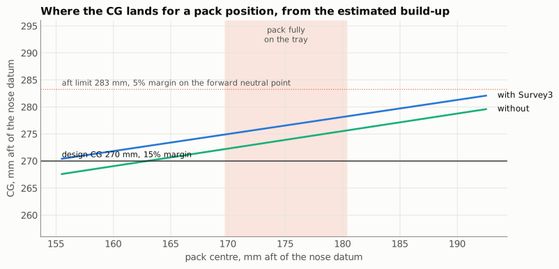
With the 6S2P P50B pack (the build’s pack since 2026-10-01). The pack is 900 g and 139 mm long, lying 72 mm wide and 48 mm tall. The Fuselage Front’s floor steps up 5.4 mm at the tray’s front edge (Y 100), and that step stops the pack: its centre can go no further forward than 169.5 mm (the pack then runs from 100 to 239 mm, held by a removable stop at 239.5). Each millimetre it moves shifts the CG 0.33 mm, which is worth about 4.2 g of nose ballast.
The first build with the kit nose (2026-10-05; history: since th-main’s dbc1183 the nose package below is the first build, and these masses predate the all-in gear and the Walksnail). Keel B with plain roots, Fuselage B with the payload bay and the Survey3W on its cover, the single-part magnet hatch and elevons, the EMAX ECO II 2807 lift motors and ECO II 3115 pusher with the APC 10x7E, and both ESCs flat in the belly between the spars: the Lucid 4-in-1 at Y 255 to 304.5 and the DYS Aria beside it on the starboard floor (Ryan, 2026-10-05). The avionics are where the first build puts them: the LUX F765 on its plate at about Y 300, the Q43 under the radome at Y 404, the MS4525DO in the nose. The component masses and positions are th-main’s table (bf93883), with 155 g of wiring from the harness routes’ cut lengths; every row there says whether it is a specification, a measurement or an estimate. A 35 g lump for screws, magnets and straps that no row lists is an estimate placed at the CG, so it adds mass but does not move the balance. With the pack against the step (tools/cg_envelope.py, first_build):
| First build, pack centre 169.5 mm | Survey3W fitted | Survey3W off, cover on |
|---|---|---|
| CG with no nose ballast | 274.8 mm | 271.9 mm |
| Nose ballast for 268 mm (the aim) | about 85 g, at the cups’ 84 g | about 47 g |
| Nose ballast for 270 mm | about 59 g | about 22 g |
| Nose ballast for 265 mm (the stall test) | about 124 g, more than the cups hold | about 85 g, at the cups’ 84 g |
| All-up mass at 268 mm | about 2.75 kg | about 2.64 kg |
The build-up carries the RunCam WiFiLink 2 (30 g with its fan) in the nose, as the parts list names it. The DJI O4 the scenes carry is about 20 g lighter there, and at the nose that costs about 20 g more ballast: 105 g for 268 mm with the camera fitted, 67 g without. Ryan chose the Walksnail Avatar HD Moonlight on 2026-10-06 (below).
The first build as it flies (2026-10-06): nose rev C, the CG trim slider, the all-in gear and the Walksnail. The nose package (th-blender 1dbefba, 285337d, 7bcbbd8; th-main dbc1183) moves the pack 14 mm forward against a pocket at Y 85, removes the ballast cups, and puts the LoRa radio in the nose; its parts are th-main’s per-part slices (6a0bfb1), net +15.1 g and the CG slightly forward. Nose rev C and the CG trim slider (th-blender d73a90b, b574a6f, c3bbe21; th-main’s per-part slices, 27d29b4) add 50.4 g, 48.8 g of it the slider: the slide tray (39.2 g in place of Battery Tray B’s 26.0 g), the 27.3 g plate under the pack, the 10 g continuous servo, the AS5600 board and the XIAO RP2040. The pack-forward stop goes, because the slider’s aft fence holds the pack, and the pack rides 3 mm higher on the plate. The Walksnail Avatar HD Moonlight (Ryan, 2026-10-06, in place of the WiFiLink 2) sits where rev C draws it: the camera (8.9 g) at Y 21 in the kit’s 21 mm cone, the VTX (29.6 g) at Y 59 on the Camera Arm. The pack and the plate, 927 g together, now move as one from a pack front of Y 80 to Y 96 (86 as drawn), and every millimetre moves the CG 0.33 mm. The landing gear is th-main’s all-in table (20f1e8c): every printed part sliced alone and every other item sourced (cores, contact strip or plate, antennas, jacks, beads, coax, leads, screws, glue). A keel weighs 95.6 g all-in on either gear, 81.7 g net of the kit motor mount it replaces, about twice the 41 g this page used for keel B until 2026-10-06: the printable keel B carries its cassette bay, 22 mm PETG core sockets and their hardware, and keel A’s 61.0 g of 2026-09-28 left out its plate, leads and beads. The front stilts are 8.1 g net a side on B and 24.4 g on A. So the CG now depends on where the pack sits (first_build(gear, pack_front); the slider ends are first_build_slider in aero/cg/results.json):
| First build | CG, pack at the forward stop (Y 80) | Pack front for 268 mm | For 265 mm (the stall test) | All-up |
|---|---|---|---|---|
| Keel A (prints today), Survey3W fitted | 265.7 mm | Y 87.2 | pack at Y 80 and about 10 g | about 2.89 kg |
| Keel A, camera off, cover on | 262.8 mm | Y 96, the aft stop | pack at Y 86.7 | about 2.81 kg |
| Keel B (decided, after its coupon), Survey3W fitted | 267.4 mm | Y 81.8 | pack at Y 80 and about 33 g | about 2.85 kg |
| Keel B, camera off, cover on | 264.5 mm | Y 90.4 | pack at Y 81.5 | about 2.78 kg |
No trim weight is needed for 268 mm on either gear. The slider puts the pack where 268 balances: set the stop pin from the balance and store that place as TAKEOFF (first flight, step 3). Each millimetre of CG is about 3.1 mm of pack (the stop pin’s holes are 2 mm apart, about 0.65 mm of CG each). Keel B with the camera fitted must not fly with the pack front aft of Y 88: it is then aft of the 270 mm hard limit, and at the aft stop it is at 272.6 mm. The stop pin and the script’s arming check hold the pack at TAKEOFF. Only the stall test at 265 mm with the camera fitted still needs trim weight, about 33 g on keel B and 10 g on keel A, with the pack at the forward stop. No trim pocket is drawn: tape it inside the nose to the Camera Arm at about Y 55, and record its mass and position on the build sheet. Weight further forward needs a little less (about 9 g at the nose datum for every 11 g at Y 55). With the camera off the slider alone reaches 265 mm. Cruise (only after the stall test and the pitch tune) moves the pack aft by CGS_CRUISE_MM = 3.0 × (270 − the measured TAKEOFF CG), rounded down to a whole millimetre and at most 8: about 6 mm from a 268 mm takeoff, so CRUISE sits at 270 mm or forward of it (th-avionics and th-aeronautics, 2026-10-07). cg_slider.lua enforces it (v1.6, th-avionics 6f61e02): the measured TAKEOFF CG goes in CGS_TKOFF_CG, the move is the smaller of CGS_CRUISE_MM and the rule, and with CGS_TKOFF_CG unset or outside 255 to 270 there is no CRUISE at all. Until then it was 8 mm, about 270.6 mm. The cap is for the fault case: a jam, a lost sensor or a slip that latches while the pack is at CRUISE holds it there, and a slowdown then flies the pitch-stiffness dip above on the wing alone until the assist; at 270 or forward that stays inside the hard edge. It costs about a quarter of the cruise benefit, about 0.3 % of drag. cg_slider.lua returns the pack forward before any planned slowdown. The all-up mass is about the same as on 2026-10-06’s earlier table (2.83 to 2.84 kg with the camera): the slider’s 49 g replaces the trim weight it no longer needs. Since 2026-10-08 the Gemfan F8041 3-blade lift props add 15.2 g (11.6 g a prop against 7.79 g; propulsion, c49c8d9), at the rotor stations either side of the CG, so they move it by less than 0.1 mm; the tables here carry them, which moved the pack fronts by 0.1 mm and the stall-test weight by about 1 g. The build-up is still an estimate of about ±20 mm until the aircraft is on the balance, and the balance decides the real place.
With the night-lights set (Ryan approved its battery 2026-10-06). Navigation and anti-collision lights (lights, th-avionics) add two strobe pods (Tail B top and the belly aft of the keels), three position lights (both tips and Tail B), a landing light near the CG and their leads, about 42 g in all and most of it far aft; th-eda’s node board, 25 g, in Mid B near the flight controller; and their own battery, a Roaring Top 1300 2S (67 g), flat on top of the flight pack on a 3.4 g TPU saddle and riding the slider with it, its centre 102.5 mm aft of the pack’s front (th-blender a8bf553). The battery carries the lights and the 1.25 W always-on rail, so in flight nothing of the lights comes from the flight pack. The rows are NIGHT_LIGHTS in tools/sitl_model.py, first_build(gear, pack_front, lights=True) here; the holder, dome and lead masses are estimates until th-blender draws the mounts.
| With the night-lights set | Mass | CG, pack at the forward stop (Y 80) | Pack front for 268 mm | At the aft stop (Y 96) |
|---|---|---|---|---|
| Keel B, Survey3W fitted | about 2.99 kg | 268.2 mm | Y 80, the forward stop | 273.5 mm |
| Keel B, camera off | about 2.91 kg | 265.4 mm | Y 87.6 | 270.9 mm |
| Keel A, Survey3W fitted | about 3.02 kg | 266.5 mm | Y 84.5 | 271.8 mm |
| Keel A, camera off | about 2.94 kg | 263.7 mm | Y 92.6 | 269.2 mm |
The slider still balances every case at 268 mm with no trim weight, but keel B with the camera now needs the forward stop itself and reaches 268.2 mm there, inside the 265 to 270 band; 268.0 would take about 2 g at the Camera Arm, which is not worth carrying. A few grams more at the tail than estimated would move it further aft, so check it on the balance. The lights’ far-aft mass is balanced by the battery riding forward of the CG and moving with the pack, which also adds to the slider’s authority. The all-up mass, about 2.99 to 3.02 kg with the 3-blade props (2.97 to 3.00 before them), raises the soft pitch band: jbsim-b3 puts it at 18.04 to 19.70 m/s on keel B and 18.15 to 19.81 on keel A (CG 268, 2026-10-07), over 19.5, so AIRSPEED_STALL is 20.6 when the lights are fitted (params/payload-lights.parm, th-avionics 68002f2: 0.90 and 0.79 m/s above the band) (on C the night build flies the common 20.0 since 2026-10-20: th-testpilot’s night A/B found no assist and no time at 9.5° true alpha or above, th-avionics 5a357f69), and the slider keeps the day’s return speeds (CGS_SPD_MIN 19.5 raw, CGS_SPD_OUT 20.0 filtered, CGS_SPD_IN 20.5). Night values of 20.0 and 20.3 were tried and dropped: inside the 21 m/s survey’s gust band they made the slider chatter, 6 to 20 moves and 34 to 106 mm of travel a survey against the day’s 2 (th-testpilot’s night A/B, 2026-10-07). They are not needed since CRUISE is capped at 270 mm: a gust that takes the speed into the band with the pack at CRUISE leaves the aircraft where a 270 mm takeoff would be, the edge already accepted (th-avionics). The return is not instant: about 3 mm/s in SITL (th-testpilot measured the 8 mm return at 2.2 to 2.9 s; the real servo’s speed is not measured yet). So in an unplanned slowdown, a gust or a pilot slowing in FBWA, the pack may still be up to about 3 mm aft of TAKEOFF as the speed crosses the band top; the CG is then about 269 mm or forward of it, and at worst, with the pack still at CRUISE, 270. Planned slowdowns (RTL, the land items, the 150 m lead) and the 20.6 floor start the return well before the band. With the lights fitted the slider alone no longer reaches the 265 mm stall-test CG, except on keel A with the camera off (pack front Y 83.7). With the pack at the forward stop the rest need weight at the Camera Arm (Y 55): keel B with the camera off reaches 265.4 mm (about 6 g for 265.0), keel A with the Survey3W 266.5 (about 22 g), keel B with the Survey3W 268.2 (about 45 g). The stall test flies first, without the lights, so this matters only for a later re-test at the night mass (th-simulator); camera-off stays the configuration to fly it in. Coverage at 21 m/s and 116 m, with the rail off the flight pack: about 282 ha calm and 274 ha in a 5 m/s crosswind on keel B, against 289 and 281 without the lights (estimate, mission).
Until 2026-10-06’s rev C update this table read, with the pack fixed at Y 86 to 225: keel A 269.2 mm with the camera (about 17 g for 268, 57 g for 265), keel B 271.0 mm (about 40 g and 81 g).
These figures are about 31 g heavier at the nose than the 54 g quoted from 2026-10-01 to 10-04. That table came from a build-up still carrying an older layout: four lift ESCs at the pods, a 60 g pusher ESC on top of the pack, and the avionics as one lump at Y 180. Each of those made the aircraft look more nose-heavy than the first build is. With the kit nose and the camera fitted, 268 mm needs the cups full, and so does the stall test at 265 mm without the camera. That is what moved the pack forward: at about 4.2 g of ballast per millimetre, the nose package’s 14 mm does what the cups did. The camera-off column keeps the payload cover on the bay.
With the kit nose the ballast sits at 56 mm aft of the nose datum (the nose package has no cups; th-blender is adding a small trim-weight place), in two washer cups either side of the Nose Plate’s camera cheeks (th-blender, tools/make_nose_ballast.py, 8755e43), because the camera fills the nose cone at 20 mm, where the earlier figures put it. Ballast further aft needs more mass for the same CG: the 47 g quoted until 2026-10-01 at 20 mm is about 55 g in the cups. These come from the same estimated build-up as everything below, with th-blender’s first masses for keel B and th-main’s sliced part-only masses for the printed fuselage (2026-10-03), each swap at its part’s centroid. The measured CG on the balance decides the real ballast. The rest of this section is the Tattu 6S 4500 analysis it replaced, kept for its reasoning.
The build-up is the component list in tools/sitl_model.py, with masses from the specifications and the print plan, and positions from the Blender assembly. The Survey3 and its mount (88 g at 382 mm) are added. It comes to 2.24 kg. The pack is 628 g, so each millimetre it moves shifts the CG 0.28 mm.
| Pack centre | CG with the Survey3 | CG without |
|---|---|---|
| 175 mm, centred on the tray | 291 mm | 287 mm |
| 158 mm, as far forward as the hatch allows | 286 mm | 282 mm |
Both are at or aft of the 5% limit. The design CG of 262 mm would need the pack centred 73 mm aft of the nose, which is inside the nose cone. So the estimate says the aircraft is tail-heavy by 25 to 30 mm. The manual’s “slightly aft of the front spar”, about 270 mm, needs about 185 g at the nose with the pack on the tray; 275 mm needs about 140 g.
Moving parts forward helps less than it looks. Each 100 mm forward moves the CG by:
| Part | CG shift per 100 mm forward |
|---|---|
| Pusher motor, prop and mount (152 g) | 6.8 mm |
| Pusher ESC (60 g) | 2.7 mm |
| Survey3 and mount (88 g) | 3.9 mm |
| Rear lift motors, both | 7.2 mm |
The pusher ESC is the only one that is free to move. Putting it in the front bay instead of behind the wing gains about 10 mm. The rest is nose weight, or a heavier nose payload that earns its place, such as the RTK GPS.
The build-up is an estimate. Its two largest terms, the printed wing and the fuselage, are each placed by one centroid guess. A 20 mm error in either moves the CG by 3 to 4 mm. Weigh the finished airframe on two points before trusting any of it.
The recommended arrangement
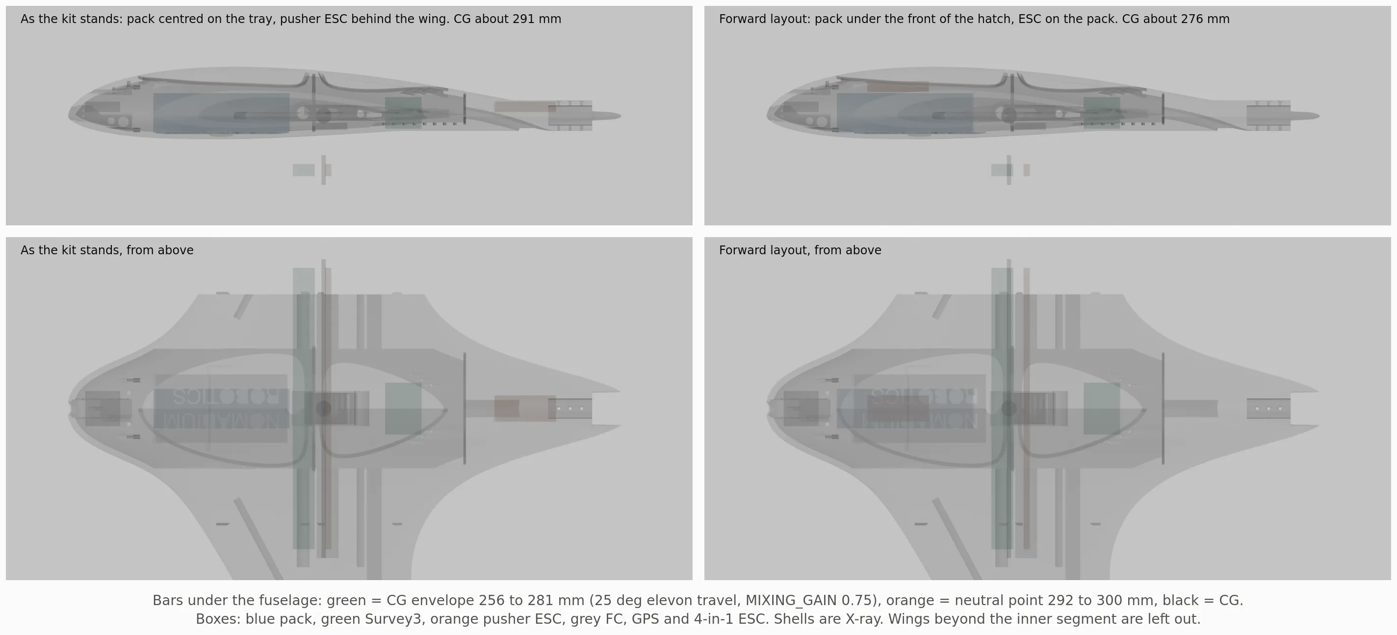
Section titled “The recommended arrangement”Two moves put the CG inside the envelope before any ballast. The pack slides forward until its front is under the front of the hatch, centre 158 mm instead of 175, still on the tray at the back. The pusher ESC moves from behind the wing to the top of the pack, where there is 29 mm of room under the hatch. The camera stays in the aft bay; the front bay has no room for it.
| Arrangement | CG, no ballast | Ballast at the nose for 270 mm (decided) | For 262 mm | All-up at 270 mm |
|---|---|---|---|---|
| Pack centred on the tray, ESC behind the wing, no landing gear | 291 mm | 185 g | 264 g | 2.43 kg |
| Forward layout, no landing gear | 276 mm | 54 g | 128 g | 2.29 kg |
| Forward layout with the keel A landing gear and pod ESCs (Tattu 4500) | 281 mm | 109 g | 190 g | 2.59 kg |
| P50B against the floor step, keel B plain, rear fuselage B, ballast cups at 56 mm (2026-10-01; its build-up still carried pod ESCs) | 272 mm | 29 g | about 135 g | 2.73 kg |
| First build, kit nose: both ESCs in the belly, Survey3W fitted, WiFiLink 2 (2026-10-05) | 274.8 mm | 59 g | about 165 g | 2.72 kg |
| First build: nose package, all-in keel B, Survey3W fitted, Walksnail (2026-10-06) | 271.0 mm | 14 g | about 122 g | 2.80 kg |
| First build: nose rev C and the CG slider at its forward stop, all-in keel B, Survey3W fitted (2026-10-06) | 267.4 mm | none | about 74 g | 2.84 kg |
The first row is how the SITL model flew on 2026-09-26: 264 g of ballast for 262 mm, 12% of the aircraft. The forward layout brought that down to 128 g and 2.37 kg. The landing gear decided on 2026-09-27 (aero, keel A) puts some of it back: two 20 mm front stilts and two 140 mm rear keels, each printed as one part with its VTOL motor mount since 2026-09-28 (the keel is the foot rather than clamped onto the kit’s), 153 g of gear in all as sliced, counting the new mounts’ extra mass over the kit’s, the E-glass keel cores and the keel antenna cassettes (keel parts), with the keels 190 mm behind the CG. On 2026-09-28 the lift ESCs also moved from a 4-in-1 in the fuselage to one ESC in a printed cradle at each pod (about 25 g per pod), and the airspeed module moved into the fuselage’s starboard lobe; both sit near the CG on average, so they add mass, about 100 g with the gear changes, but barely move it. With the CG at 270 mm that takes 109 g at the nose and the all-up mass to 2.59 kg, which is what the SITL model and the aero, propulsion and mission pages now use; holding 262 mm instead would need 190 g. At 2.59 kg stall onset is 13.7 m/s, hover draws about 23 A instead of 19, and a pack maps about 135 ha instead of 150 at 2.25 kg. Every gram taken out of the keels is worth two at the nose, which is why they are hollow LW-PLA shells; the masses follow th-blender’s slicer and get replaced by the scale once the parts are printed.
The cost of the forward layout is wiring. The pusher ESC sits about 480 mm from its motor instead of 110, so the three motor leads run the length of the wing bay. Keep them twisted, and keep the ESC’s signal lead away from them.
Both rows use the same estimated build-up. So the ballast numbers carry its ±20 mm of CG uncertainty, which is about ±180 g of ballast. Fix the real amount on the balance, not from this table.
Weigh and balance
Section titled “Weigh and balance”The front spar is at 267.7 mm, which is inside the envelope. So the balance check needs no jig. Fit the pack, the camera and the props. Then hold the aircraft by the front spar bolts, or rest the spar on two fingers.
- Nose drops gently: the CG is ahead of 268 mm. Good, as long as the elevons can trim it (see the forward limit).
- Level or tail drops: the CG is at or aft of 268 mm. Add weight at the nose until the nose just drops.
For a number, weigh the aircraft on two scales, one under the nose and one under the tail. Take moments about the nose datum. Write the result on the airframe. Check it again after any change to the payload or the pack.
Limits
Section titled “Limits”The forward limit assumes the elevon tables stay straight to 15° of deflection, which is where the runs end. The aft limit uses a vortex-lattice neutral point; the real one can differ by the width of the band in the figure. The build-up is not measured. None of these replaces the balance check above.
How it was done
Section titled “How it was done”PYTHONPATH=tools uv run --with numpy --with matplotlib python tools/cg_envelope.pytools/cg_envelope.py uses the fitted elevon tables from tools/aero_report.py and the component list from tools/sitl_model.py. It writes aero/cg/results.json and the figures in docs/cg/.
Source: docs/cg.md in the repo. Edit it there; this page is generated.
Comments
Comment on the whole page here, or on one section or step with the button beside it.