
Wing Aerodynamics
What the TerraHawk wing does in the air, worked out from the STL pack with XFOIL, OpenVSP 3.53 and VSPAERO 7.2, then checked against what the assembly manual says. Everything here is reproducible from the scripts listed at the end, and every figure regenerates from the result files. Analysed 2026-09-26 at a nominal all-up weight of 2.25 kg (the 6S cart plus the Survey3 mapping payload), with 2.0 and 2.5 kg alongside.
The short version: the neutral point and CG the manual gives are what the aerodynamics say too. The wing trims with its elevons trailing edge up at every useful speed, stalls across the elevon span all at once, and loses more cruise efficiency to the parked VTOL hardware than to anything else.
The wing, measured
Section titled “The wing, measured”Nomadium does not publish span, chord or airfoil, so they come from slicing the assembled right half of the kit at thirteen spanwise stations and fitting the section outline at each. The OpenVSP model built from those slices matches the STL pack to the millimetre in leading edge, chord and leading-edge height at every station, including the drooped tip.
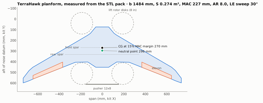
| Quantity | Value |
|---|---|
| Span | 1484 mm |
| Reference area (centre body included) | 0.274 m² |
| Mean aerodynamic chord | 227 mm |
| Aspect ratio | 8.0 |
| Leading-edge sweep | 30.4° (the elevon hinge line is 21.7°) |
| Chord | 378 mm on the centreline, 185 mm at the panel root, 111 mm at the panel tip |
| Elevons | 30% chord, 368 to 644 mm from the centreline |
| Wing loading at 2.85 kg, the first build | 10.4 kg/m² |
The tip is not a winglet in the usual sense. The part called Winglet droops the last 100 mm of span down by 20 mm, and the Winglet Stabilizer on top is a small fin that leans forward as it rises and cants about 20° inboard.
The sections are about 10% thick with the maximum at 29% chord. Camber fades from 2.5% at the VTOL section to almost nothing at the panel tip, and nowhere is there trailing-edge reflex.
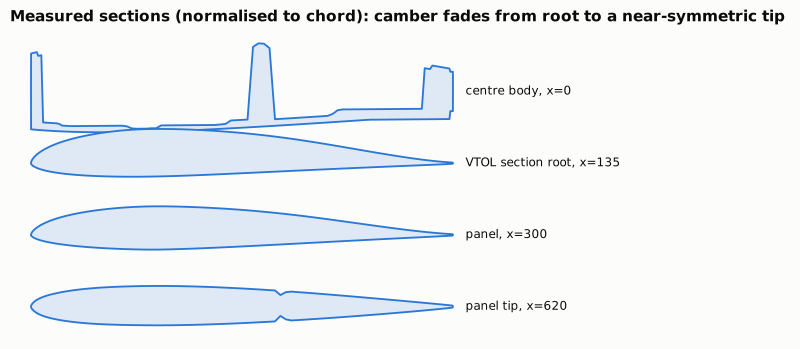
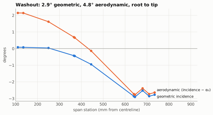
That camber fade matters as much as the geometric twist. The panel twists 2.9° nose down from root to tip, and the zero-lift angle moves from -2.0° at the root to -0.1° at the tip as the camber goes. Together they give 4.8° of aerodynamic washout.
Pitch stability and the CG
Section titled “Pitch stability and the CG”A flying wing has no tail to trim it, so it trims with sweep and twist. The swept panels put the washed-out tips well behind the cambered root, and at cruise the tips carry little or even negative lift behind the CG, which is what a tail would otherwise do. The sections themselves all pitch nose down (cm₀ of -0.037 at the root, about zero at the tip), so sweep and washout have to cover that and then some.
VSPAERO puts the neutral point at 292.5 mm aft of the nose datum from its stability derivatives and 299.8 mm from the slope of the pitch polar. The two methods bracket it, so this page uses the average: 296 mm. The manual says the neutral point is “slightly forward of the Rear Fuselage Spar” (333 mm) and the CG “about 15% forward of the Neutral Point, which puts it slightly aft of the Front Fuselage Spar” (268 mm). The second statement is the precise one, and it implies a neutral point near 302 mm, within 6 mm of the result here.
A 15% static margin puts the CG at 262 mm, 6 mm ahead of the front spar. Anywhere from there back to 271 mm gives 11 to 15% margin, which is a sensible window to aim the battery position at.
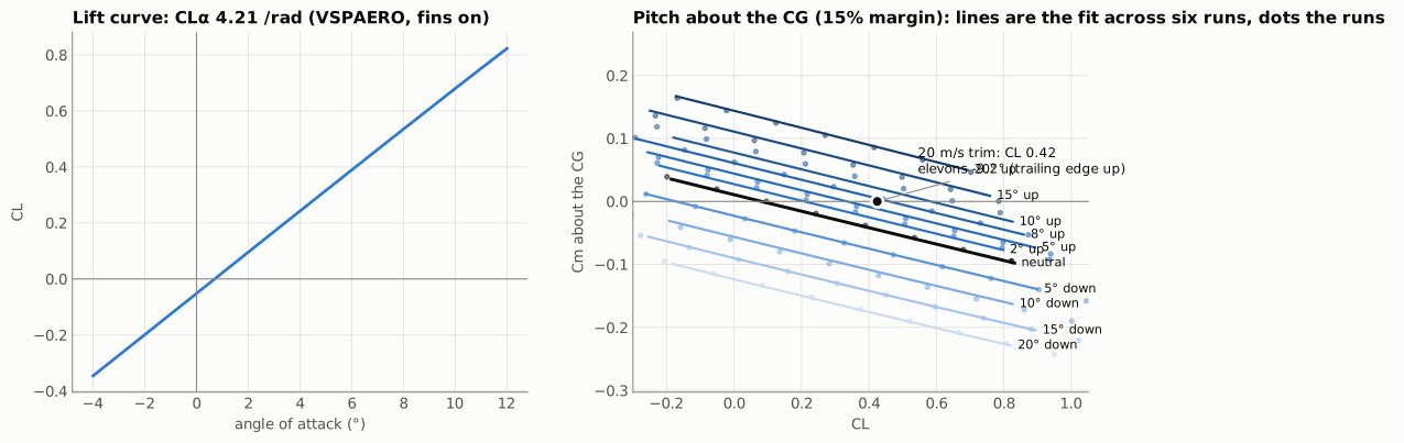
About that CG the wing’s own pitching moment reaches zero at CL 0.07, so it trims hands-off only near zero lift. Every real flight condition needs the elevons trailing edge up. At 20 m/s and 2.25 kg that is 6.8°, and at 16 m/s about 11.5°. The elevons are powerful (Cm_δe = -0.51 per radian, CL_δe = 0.87 per radian), so the throw is there, but most of the down elevon travel is spent before you touch the stick, and ArduPilot will spend its first minutes of tuning discovering the trim. Setting the elevon linkage 5 to 7° up at neutral servo, or using TRIM_PITCH_DEG, gives the autopilot a centred starting point.
Six VSPAERO runs, from 15° up to 10° down, set the elevon effect. Single runs scatter by about a 5° step (0.03 in CL), so each quantity is a straight-line fit through all six. The ±5° pair on its own read about 30% low. Trim drag is included: the up elevons unload the tips, and the deflected wing’s own induced drag is what the tables below use.
Span loading and stall
Section titled “Span loading and stall”At cruise the loading is fuller inboard and lighter outboard than an elliptic distribution with the same lift. That is the washout doing its job, and it costs induced drag: the span efficiency is about 0.3 when trimmed at the 20 m/s cruise lift coefficient, because the up elevons unload the tips further. The untrimmed wing reaches about 0.65 near CL 0.5. At high speed it falls further, when the drooped tips carry negative lift.
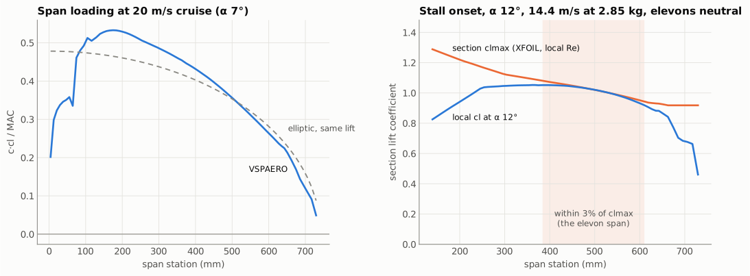
The right-hand panel compares each strip’s lift with the XFOIL clmax for its own section at its own Reynolds number. The centre body and VTOL sections keep a wide margin, and the drooped tip is safely unloaded. But the whole outer panel from about 360 to 630 mm, which is exactly the elevon span, reaches its limit at the same time, at 12° angle of attack. The thin, nearly symmetric tip section at Reynolds numbers near 100k has a much lower clmax (0.92) than the root (1.27), and 4.8° of washout only just covers the difference.
In practice that means the stall will not be the gentle nose drop a washed-out wing usually gives. Separation across the elevon span costs roll control first, and whichever side goes first drops a wing. Two things soften it in flight: the trimming elevons are up at low speed, which unloads that part of the span, and the Q_assist lift motors take over below 14 m/s. That is a good reason to leave Q_ASSIST_SPEED exactly where the manual puts it.
| AUW | Stall onset, elevons neutral | Q_ASSIST_SPEED | AIRSPEED_MIN |
|---|---|---|---|
| 2.25 kg | 12.8 m/s | 18 m/s | 18 m/s |
| 2.85 kg, the first build (2.75 kg until 2026-10-06: 14.1 m/s; 2.59 kg with the Tattu pack until 2026-10-01: 13.7 m/s) | 14.4 m/s | 18 m/s | 18 m/s |
| 2.9 kg | 14.5 m/s | 18 m/s | 18 m/s |
The two speed columns are the schedule decided on 2026-09-27 (the guide’s defaults were 14 and 16 m/s). They are not set against the onset in the table but against the trimmed stall, which is higher, because the up elevon that trims the wing costs lift. That is the next paragraph, and it is why the schedule moved twice in a day: Q_ASSIST_SPEED 16 for a few hours on the simulator’s first reading, then 18.
Trimmed stall, 2026-09-27. That last sentence was too kind, and th-simulator’s stall probe at the 270 mm CG showed it. The onset speeds in the table are with the elevons neutral. A flying wing never flies that way: at low speed the elevons sit 10° trailing-edge up to hold the nose, and that costs lift exactly where lift is scarce. From the same model, the trimmed angle of attack reaches 12° at 15.5 m/s on the keel build (2.48 kg, 270 mm; 15.7 at 2.59 kg, about 16.2 at 2.75 kg and 16.5 at the first build’s 2.85 kg by mass scaling), 14.5 m/s at 2.25 kg, carrying 10.6° of up elevon. The simulator reads 17.8 m/s on the same aircraft, and the difference is its stall model: SIM_Plane blends the lift toward a flat plate through a sigmoid of width mcoeff 50 centred on 12°, which has given away 15% of the lift by 10° and 29% by 11°, so it stalls near 10.5° at about 0.8 of the linear lift, and 15.5 × √1.25 is 17.3. The same probe with mcoeff 100 (3% blended at 10°, 15% at 11°) reads 16.7 m/s with a sharp break, so the blend width is worth about 1.1 m/s (th-simulator, 20260927T171000Z). th-testpilot’s stall-test rehearsal on the current flight model (2.59 kg, keel, no tip fins) stalled wings level at 17.9 m/s equivalent airspeed with the default blend and 17.1 m/s with mcoeff 100 (2026-09-28); at 2.59 kg the design value scales to about 16.8 m/s. Real sections at this Reynolds number round off over a degree or two before CLmax, so the truth is between 15.5 and 17.8 m/s, and about 16.5 is the number to design to until a stall test in FBWA at altitude replaces it, which is the first item on the flight-test list.
A trimmed stall near 16.5 moves the speed schedule. Q_ASSIST_SPEED 16 is at the stall rather than above it; 18 m/s, the survey speed the mission page prefers, is only 1.1 times the stall; and the guide’s AIRSPEED_MIN 16 is below it. The schedule that fits is Q_ASSIST_SPEED 18, AIRSPEED_MIN 18, AIRSPEED_CRUISE 22, with the survey flown at 20 m/s, which the mission table already prices at 143 ha per pack against 151 at 18 m/s. Decided 2026-09-27, with the energy cost accepted; the flight parameters carry the rows and the CG page now sets its forward limit at 18 m/s. Bank raises the stall by the square root of the load factor: 16.5 m/s level is 18.2 m/s at 35° and 19.6 m/s at 45°. th-simulator’s return-turn tests departed in 3 of 8 flights at 45° and 22 m/s in 5 m/s gusts and none at 35°, so the parameter set limits bank to 35° (ROLL_LIMIT_DEG), a 70 m turn radius at 22 m/s. Those gusty results, and every other gusty departure rate from the simulator on 2026-09-28, came from SITL’s built-in turbulence, which is close to white noise at 1200 Hz and jitters the angle of attack by about ±1.7°, far rougher than real air. With MIL-F-8785C (Dryden) low-altitude gusts in the test harness instead, 34 turn-backs in a row had no departures, so those rates are upper bounds; the 35° limit stays until the stall test gives a measured margin. AIRSPEED_STALL is 20.0 m/s (th-avionics, 0634db5, 2026-10-01; 19.2 from 2026-09-28). It is a margin setting, not the stall: 9% over SITL’s wings-level stall of 18.34 m/s EAS at 2.73 kg, and about 20% over the CFD’s trimmed estimate of 16.6. ArduPlane’s stall prevention holds a turn at AIRSPEED_STALL × √(load factor) or faster, 22.1 m/s at 35°, and in th-testpilot’s gusty survey sets at 21 m/s that kept every turn’s angle of attack at 11° or below, where at 19.2 the peaks reached 11 to 15°. The cost is about 1 Wh per 100 ha of survey. The stall test will replace it with a measured value, and it can come down if the real stall is lower. Height is guarded as well: Q_ASSIST_ALT is 30 m (th-avionics, 2026-09-28), so the lift motors step in below 30 m whatever the airspeed, after the simulated turn-backs departed 3 times in 16 without it and never with it.
Lateral and directional stability
Section titled “Lateral and directional stability”The full-model stability run gives a dihedral effect of Cl_β = -0.022 per radian from the sweep, which is stable, and a directional stability of Cn_β = +0.008 per radian, which is stable but only just. Yaw damping is weak too (Cn_r = -0.009). The model leaves out the fuselage, which usually costs directional stability, so the real aircraft may sit closer to neutral in yaw. Expect some tail-wag in gusts and a slow Dutch roll at low speed, which is normal for a flying wing of this size. It is worth watching in the first FBWA flights, and the rudderless yaw settings in ArduPilot are the tool if it bothers the autopilot. The cheap fix turned out to be the landing gear: the stilt feet, sized as ventral fins with a wider rear pair, double Cn_β for about 3 W. See the stilt section under drag and performance.
Drag and performance
Section titled “Drag and performance”Profile drag comes from strip theory: every VSPAERO strip gets the XFOIL drag for its own section at its own lift coefficient and Reynolds number. XFOIL does not converge on the 20% thick centre body, so that part uses a turbulent flat-plate estimate with a thickness form factor. The pusher pod, hatches, fins and VTOL hardware are hand estimates from their frontal areas.
Since 2026-10-01 the trimmed drag is the CFD’s. The drag figure and the performance table below come from the whole-aircraft fine CFD (Ryan, 2026-10-01). Its α sweep gives lift, pitching moment and drag. Its ±10° elevon pair gives the elevon’s lift, moment and drag, and the aircraft is trimmed at the CG on those. The build’s differences from the CFD geometry are added as estimates: keel B plain −0.0011 against keel A, the fuselage B spine +0.0009 against the kit hatch, and 0.0010 for the lift ESC cradles. The reason for the change: the VSPAERO elevon runs with the trailing edge up stop being physical past −7.5° (lift is not monotonic, and CDi/CL² reaches 1.4), and the trimmed drag fitted through them read 9% high at 20 m/s and 25% high at 30 m/s. Strip theory still gives the stall onset and the section loads. In the drag figure the hand-estimated items are listed, and the rest of the CFD total is one bar. The elevon pair is at α 6.7° only, so trim drag far from cruise is an extrapolation in deflection.
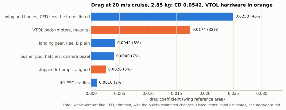
The four VTOL pods (motor, mount and the bottom of the spar) are the largest single item, more than the wing’s own profile drag, and together with the parked props they make up 38% of cruise drag. Parking the props in line with the airflow matters a lot. Across the flow they add another 0.018 to CD, 1.2 N at 20 m/s, which is about 40 W of electrical power and takes pure-cruise endurance from 87 minutes to about 65.
Stilt feet. Decided 2026-09-27: four 120 mm stilts under the motor mounts, so the pusher prop and the belly camera clear the ground, and the hangar’s guided pad can funnel the feet onto its contacts. They fly through the airflow all flight, so their section matters more than their length. Hand estimates for four 120 mm posts at 20 m/s:
| Stilt section | Added CD | Added cruise power | Pure-cruise endurance |
|---|---|---|---|
| Round, 10 mm | 0.019 | about 50 W | 35 to about 26 min |
| Round, 6 mm | 0.011 | about 30 W | 35 to about 30 min |
| Streamline, 3:1, chord along the airflow | 0.003 | about 7 W | 35 to about 33 min |
A bare 10 mm post costs more than the VTOL pods, the largest item above. So the stilts are a streamline section, about 8 mm thick by 24 to 32 mm chord. They are not in the breakdown yet; they go in once the part is designed and its section is known.
Stilts as ventral fins. Four vertical blades hanging under the motor mounts are four small fins, two ahead of the CG and two behind it. So the question came up whether they could do some of the work of a tail. With equal chords they cannot. The front pair pushes the nose away from the wind about as hard as the rear pair pulls it back, and Cn_β stays where it was. Giving the pairs different chords works. VSPAERO stability runs at 4° and 20 m/s, with the stilts as thin plates from 48 to 168 mm below the datum at X ±190, Y 68 and 484:
| Stilt chord, front / rear | Cn_β (/rad) | Cn_r | −Cl_β / Cn_β | Added cruise power |
|---|---|---|---|---|
| No stilts | +0.008 | −0.009 | 2.7 | 0 |
| 28 / 28 mm | +0.009 | −0.018 | 2.2 | 5 W |
| 28 / 60 mm | +0.012 | −0.018 | 1.5 | 8 W |
| 28 / 80 mm | +0.013 | −0.019 | 1.2 | 9 W |
| 28 / 100 mm | +0.013 | −0.019 | 1.3 | 10 W |
| 20 / 60 mm | +0.016 | −0.017 | 1.1 | 7 W |
| 20 / 80 mm | +0.017 | −0.018 | 0.9 | 8 W |
| 20 / 100 mm | +0.017 | −0.018 | 1.0 | 10 W |
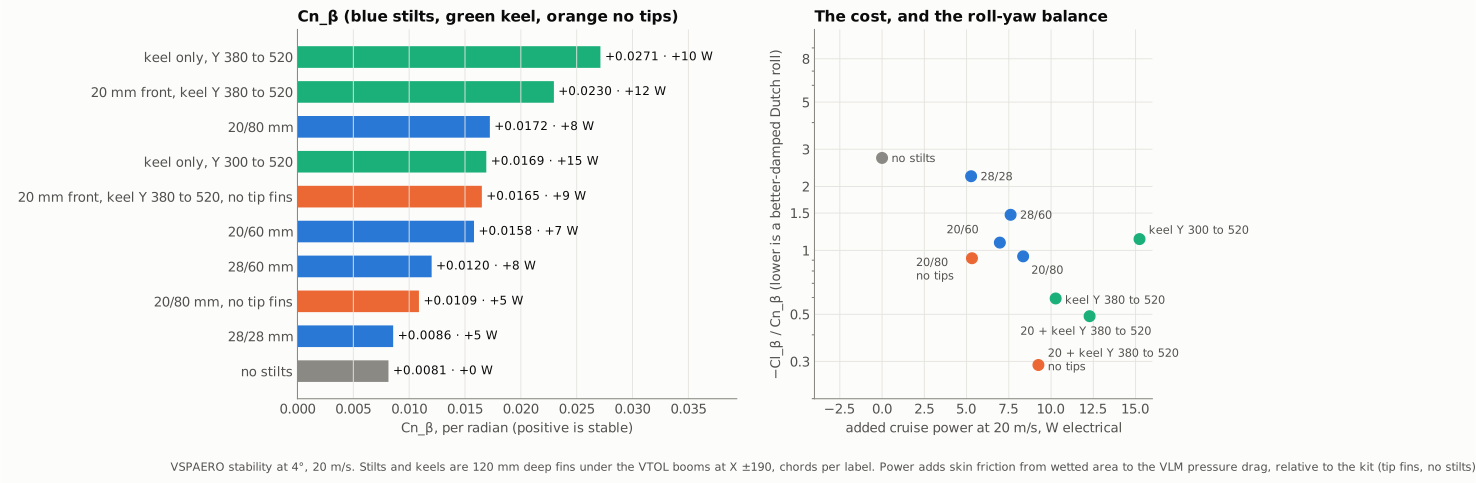
Two things stand out. The front chord is the lever: taking 8 mm off the front pair is worth about +0.004 per radian whatever the rear pair does, because the front stilts sit nearly as far ahead of the CG as the rear ones sit behind it. The rear chord saturates: 60 to 80 mm buys +0.001, and 80 to 100 buys nothing, because a 120 mm tall blade with a 100 mm chord is a fin of aspect ratio 1.2, and fins that stubby make less side force per unit area. The 20 / 80 pair takes Cn_β from +0.008 to +0.017, doubles the yaw damping, and brings −Cl_β / Cn_β from 2.7 down to 0.9. That ratio is what decides how well the Dutch roll is damped, so this is the number that matters in flight. It costs about 3 W over plain 28 mm stilts, 8 W in all, and the pitch side does not move: the neutral point is 292 mm with or without them.
Caveats, in order of size. The model has no fuselage or pods, and the pods sit right above the stilts. A 20 by 8 mm front blade is a fat section, so its real drag is a little above the estimate. And the front stilts carry the nose-heavy end of the aircraft at touchdown, so 20 mm is a structural question for the hangar design as much as an aerodynamic one. Recommended 2026-09-27: front 20 mm chord, rear 80 mm, both 8 mm thick, chord along Y, centred on the mounts. The rear blade then runs from Y 444 to 524.
Compared with the tip fins. The same runs with the Winglet Stabilizers removed put a number on what the tips do. The stabilizer is its own printed part, 56 mm tall with a 110 mm root chord, about 41 cm² each; the drooped Winglet under it closes the tip and stays either way.
| Configuration | Cn_β (/rad) | Cn_r | −Cl_β / Cn_β | Cruise power against the kit |
|---|---|---|---|---|
| Kit: tip fins, no stilts | +0.008 | −0.009 | 2.7 | 0 |
| No tip fins, no stilts | +0.002 | −0.006 | 8.5 | −3 W |
| No tip fins, 28 / 28 mm stilts | +0.002 | −0.015 | 5.5 | +2 W |
| No tip fins, 20 / 80 mm stilts | +0.011 | −0.015 | 0.9 | +5 W |
| Tip fins and 20 / 80 mm stilts | +0.017 | −0.018 | 0.9 | +8 W |
The tip fins are worth +0.006 of Cn_β; the 20 / 80 stilts are worth +0.009, with three times the yaw damping the fins give. The stilts are the better fin for three reasons. They have more than twice the area at about the same arm from the CG. They sit below the CG, where their side force pulls the dihedral effect down toward a balanced Dutch roll, while the tip fins sit above it and push the other way. And they are not on the wingtip, which is the part that meets the ground first. The tip fins are not winglets in the drag sense either: at cruise CL they cost about 0.0007 of pressure drag in this model rather than saving any, so with the skin friction they are worth about 3 W.
In the simulator, the keel with and without the stabilizers flew the same gust step and crosswind landing within a degree; the only difference was 0.1° of roll against 0.4° in the gust, which is the missing dihedral effect (th-simulator, 20260927T153656Z). The spiral mode is where that shows. From the vortex-lattice derivatives its time to double would be about 110 s for the kit and about 20 s for the keel aircraft with or without tips; flown in SITL with the roll loop switched off, the keel aircraft instead held a 5° bank for 20 s with no divergence (th-simulator, 2026-09-28), which is what a near-zero dihedral effect and a steady turn with no sideslip give. So the spiral is close to neutral: invisible under the autopilot, and by hand a bank simply stays where it is put. So the stabilizers can come off once the keel is on, and the aircraft is still stiffer in yaw than the kit. What goes with them is half the dihedral effect (Cl_β from −0.022 to −0.010, which means less roll from a side gust, neutral to good under an autopilot) and whatever fence effect they have on the tip, which the stall picture above does not depend on. It is a flight-test decision rather than a design one: fly the first flights with both, then pull the two fins and compare the yaw response in the logs.
A rear keel instead of rear stilts. The follow-up idea (2026-09-27): one fin per side running along the VTOL spar line under the spar, like a tip fin moved inboard, doubling as a landing skid. Same depth as the stilts, from 48 to 168 mm below the datum, one per side at X ±190, and no front stilt unless the row says so:
| Keel per side, Y range | Chord | Cn_β (/rad) | Cn_r | −Cl_β / Cn_β | Cruise power against the kit |
|---|---|---|---|---|---|
| 300 to 520 mm | 220 mm | +0.017 | −0.011 | 1.1 | +15 W |
| 340 to 520 mm | 180 mm | +0.022 | −0.012 | 0.7 | +13 W |
| 380 to 520 mm | 140 mm | +0.027 | −0.013 | 0.6 | +10 W |
| 420 to 540 mm | 120 mm | +0.031 | −0.016 | 0.5 | +9 W |
| 440 to 560 mm | 120 mm | +0.034 | −0.016 | 0.4 | +9 W |
| 20 mm front stilts, keel 380 to 520 | 20 / 140 mm | +0.023 | −0.016 | 0.5 | +12 W |
| The same with the tip fins removed | 20 / 140 mm | +0.017 | −0.013 | 0.3 | +9 W |
Shorter and further aft is better, which is the opposite of what a bigger fin suggests. The side force is set by the 120 mm depth: CS_β is −0.23 for every keel in the table, because these are fins of aspect ratio 0.5 to 0.9 and a fin that stubby makes side force in proportion to its depth more than its chord. What grows as the leading edge moves aft is the arm to the CG. A keel that starts at the CG wastes its front half. The practical version keeps thin front stilts, because the aircraft still lands on three points, and gets +0.023 with the tip fins on, 2.8 times the kit, for 12 W. Pushing the keel back to 420 to 540 mm would add about 0.004 more if the spar can carry it.
Decided 2026-09-27: keel A, 20 mm front stilts and a rear keel from Y 380 to 520 per side, tip fins kept. As a part, the keel’s top edge follows the VTOL spar underside forward of the rear mount and the mount’s V behind it, so the landing load goes into the spar, and its leading edge is raked so a skid sliding into the hangar trough presents no forward corner. The keel’s bottom edge carries a sole plate, 25 to 30 mm wide and 3 to 4 mm thick with rounded edges and turned-up ends, in PETG or TPU-edged: it spreads the ground load on soft ground where an 8 mm edge would cut in, gives the hangar’s brass contact plate a flat 30 by 140 mm home, stiffens and protects the shell’s edge, and acts as an end plate on a fin of aspect ratio 0.9, which raises its side force. The vortex-lattice model cannot resolve that T-junction (it returns an artefact), so the end-plate gain is unquantified and left out of the numbers; the sole’s friction is under 1 W. The keel is a hollow LW-PLA shell over an E-glass core, printed as one part with its VTOL motor mount: 61 g per side with its sole, contact plate and antenna cassette, and 16 g per front stilt, as sliced (keel parts). Sitting behind the CG, the keels add to the nose ballast; with the CG at 270 mm, decided the same day (CG page), the gear costs about 250 g of flying mass with its lead. Solids, parts and renders: aero/keel/, parts/, blender/renders/keel/ (th-blender).
Against the 20 / 80 stilts the keel costs 4 W more for a third more Cn_β, so per watt the two are even, and the keel wins on the ground: a skid in the hangar trough aligns the heading by itself, and the sole area stops being the limit on touchdown attitude. It does not improve forward flight in any other way. Only a tip device touches induced drag; a fin under the wing adds skin friction and a little interference. With the tip fins removed as well, Cl_β falls to −0.005, almost no roll response to sideslip. Under ArduPilot that is harmless. By hand the wing no longer self-levels, so a keel should keep the tip fins.
In the simulator. th-simulator flew the kit, the 20 / 80 stilts with and without tip fins, and keel A through the same three tests on the stock loops (docs/agent-threads/hangar-aero/20260927T145016Z-th-simulator-variants-side-by-side.md). The hangar landing matrix cannot tell them apart, by construction: in a hover the wing makes no lateral force in the model and all four lean on the same rotor drag. A 5 m/s side gust in FBWA at 18 m/s ranks them as the derivatives say: the keel turns into the wind fastest and rolls least (1.5 s, 0.4°), the kit slowest with the most roll (2.5 s, 1.3°) and a second excursion at 7.5 s that none of the fin variants repeat. No variant shows a Dutch roll, and the stilts-only model needs no retuning.
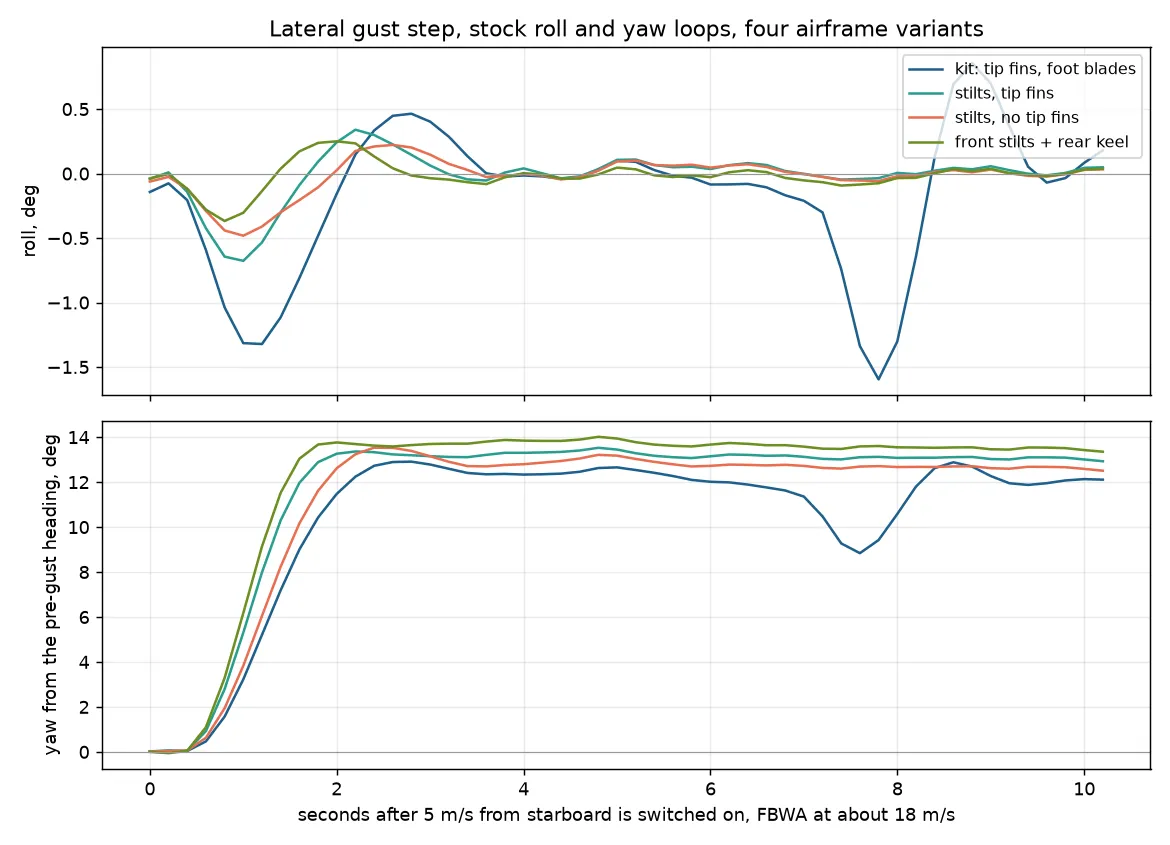
Two things the keel changes at low speed. QLAND keeps the cruise crab to touchdown on every model, and the keel crabs hardest, 29° in 8 m/s of crosswind against 19 to 21°, so an arrival from cruise must yaw onto the pad axis before it descends. And in the back-transition the keel model swings 16 to 19° in yaw and rebounds 6.7° before the heading integrator brings it back, about 14 s in all; a second look showed that to be one rebound, not a lightly damped mode. The fins are a yaw spring against the rotors’ heading hold (Cn_β q S b is 0.09 N·m per radian at 4 m/s on 0.14 kg m² of yaw inertia, an 8 s period if it rang), with aerodynamic damping near a ratio of 0.05, so the rotors’ yaw-rate loop supplies the damping. Raising Q_A_RAT_YAW_P from 0.2 to 0.3 cuts the rebound to 4.2°; D does nothing here (docs/images/sitl/keel-yaw-retune.png, th-simulator, 20260927T150135Z). That is the one parameter note the keel build carries.
Hovering nose-across an 8 m/s wind on the keel model held heading within 1.7° with the yaw mixer at about 13% of its range. That test cannot see the fins, though: the SITL wing model zeroes the lateral derivatives when the flow is along the span, which is exactly the crosswind hover. By hand, the keel broadside to 8 m/s is a flat plate: about 1.6 N of drag on the rear pair at 190 mm behind the CG, less 0.2 N on the front stilts ahead of it, 0.26 N·m nose-into-wind. The four lift rotors’ differential-torque authority at hover is 0.3 to 0.4 N·m, so an 8 m/s broadside hover is holdable with little margin, and 5 m/s (0.1 N·m) is easy. The better answer is not to hold it: with Q_WVANE_GAIN 1 (Q_WVANE_ENABLE already defaults on for plane builds; the gain is the switch) the simulated aircraft weathervaned 0 to 80° in 12 s with no overshoot and settled nose-in at 0.8° of roll. So with a keel the aircraft weathervanes in VTOL flight, and the pad axis faces the prevailing wind, which the tailwind result already demanded; the skid in the trough takes up the last few degrees.
The simulator can now see the keels in a crosswind hover (th-simulator added a crossflow drag term for them on 2026-09-28, built from the keel and stilt areas). With the heading held broadside, the yaw demand grows from 150 µs of the motors’ pair difference at 5 m/s to 400 at 8, 570 at 10 and 770 at 12 m/s, where one motor reaches 1900 µs; the heading wanders 3°, 11°, 24° and 35°. So heading hold across the wind is good to about 8 m/s and runs out near 12. Landing into the hangar with the heading aligned and then released, the simulator passes from ahead up to 8 m/s and across up to 5 m/s; at 8 m/s across, the keels pull the nose 6 to 17° after the release and the aircraft leans 10 to 12°. 5 m/s across the box is the docking limit.
An inverted T: a stabilizer between the keels. The keels invite one more idea, a horizontal plane spanning between them at the ground line, a T-tail hung under the aircraft instead of on top. Run on the wing alone (the VLM cannot handle the plane meeting the keels; their bottom-edge wakes lie in its plane), a 364 by 80 mm plate at Y 500 to 580 moves the neutral point 12 mm aft and raises the pitch stiffness by half; 100 mm at Y 510 to 610 gives 17 mm. At zero incidence it lifts upward behind the CG and worsens the cruise trim; set at about −5° it would carry the trim and let the elevons sit near neutral at cruise, which is the real prize. The mass argument is thin: 70 to 100 g less lead against a 50 to 65 g tail. The two problems are that the plane’s outer 90 mm on each side sits under the rear lift rotors, which is download in every hover and a pitch upset at touchdown, and that its lateral effect cannot be read from this model at all. Not for the first build; worth a RANS run if flight test shows the elevon trim or the forward CG limit biting. Cases ht80@540, ht100@560 and ht80@580 in tools/vsp_stilts.py.
A rudder on the keel. Tempting for survey lines with a nadir camera, and not worth it. A wing turns by tilting its lift; a rudder alone turns through the side force of sideslip, and with CS_β of −0.34 that gives about 4 N at 10° of sideslip, a turn radius near 250 m at 20 m/s. A survey turnaround needs a tenth of that. ArduPilot has no flat-turn mode for planes, and a rudder on a fin below the CG rolls the aircraft the wrong way while it yaws. For the camera, 3° of bank at 100 m shifts the footprint 5 m, which the 70% side overlap absorbs. What a rudder would add on a straight line, coordination and crab, the keel’s yaw damping provides with no servo, linkage or failure mode. If nadir imagery in turns ever matters, a camera gimbal is the tool.
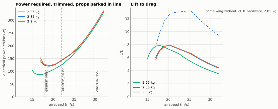
The dashed line in the L/D panel is the same aircraft with the VTOL pods and parked props removed, which peaks near 13.2 at 25 m/s. With them, the aircraft peaks at 7.8 at 20.5 m/s. Below 18.5 m/s the drag rises faster than the induced drag alone, because the CFD sees the flow change in the pitch-stiffness dip near α 9.5°; so the least power is at 19 m/s, and 17 m/s is the lowest speed that trims at this mass. All of this section is at 2.85 kg, the first build as it flies (CG, 5856776), and the CG at 270 mm (2026-10-06; at 2.75 kg from 2026-10-01, the least power at 18.5 m/s; the landing gear drag is keel B with plain roots, CD 0.0042, scaled from keel A’s 0.0048 by the coarse CFD gear-group ratio, an estimate). Until 2026-10-01 it was at 2.59 kg with the Tattu 6S 4500 pack; the earlier figures are in the git history.
| At 2.85 kg, CG 270 mm | 17 m/s | 18 m/s | 20 m/s | 22 m/s | 25 m/s | 30 m/s |
|---|---|---|---|---|---|---|
| CL | 0.59 | 0.52 | 0.42 | 0.35 | 0.27 | 0.19 |
| Angle of attack | 10.8° | 9.2° | 7.0° | 5.6° | 4.1° | 2.6° |
| Elevon trim (TE up) | 10.4° | 10.1° | 9.2° | 7.7° | 6.0° | 3.8° |
| L/D | 6.0 | 7.2 | 7.8 | 7.5 | 6.6 | 5.0 |
| Drag, pusher thrust needed | 4.6 N | 3.9 N | 3.6 N | 3.8 N | 4.2 N | 5.7 N |
| Electrical power | 141 W | 123 W | 124 W | 142 W | 177 W | 282 W |
| Pure-cruise endurance | 74 min | 84 min | 84 min | 73 min | 58 min | 37 min |
| Pure-cruise range | 75 km | 91 km | 101 km | 96 km | 88 km | 66 km |
Electrical power is the pusher’s, from the propulsion model (the V3115 on APC’s measured 10x7E data, about 0.70 prop efficiency at cruise), plus 6 W for the avionics; until 2026-09-28 this row assumed a flat 0.60, which read about 18% high. It is the same basis as the mission page and the SITL pusher. Endurance is on 80% of the 6S2P P50B pack (173 Wh, at 21.6 V nominal) with no hover or transition in it, so a real mission with two transitions and a few minutes of hover will be well short of it. The manual’s AIRSPEED_CRUISE of 20 m/s is a good default: it is the best range speed, and flying slower buys almost nothing, under 1% more time at 18 m/s (2% at 2.75 kg). Until 2026-10-01 this table was on the VSPAERO trimmed drag, which put the least power near 16 m/s and promised 20 to 40% more time at 16 to 18 m/s; the CFD does not show it. The trim in this table is the CFD’s, as on the CG page.
Hover and the lift motors
Section titled “Hover and the lift motors”Momentum theory with the measured 8 inch disks, a figure of merit of 0.60 and 0.80 for the motor and ESC gives these hover numbers. They include about 5% of download: the rotors sit entirely fore and aft of the wing, so almost none of their wake hits it, and nearly all the download is the 14 mm spar running under each disk.
| AUW | Thrust per rotor | Electrical power | Current at 21.6 V | Pure hover on 8.0 Ah |
|---|---|---|---|---|
| 2.25 kg | 591 gf | 417 W | 19.3 A | 25 min |
| 2.75 kg, the P50B build until 2026-10-06 | 722 gf | 563 W | 26.0 A | 18 min |
| 2.85 kg, the first build | 748 gf | 595 W | 27.5 A | 17 min |
| 2.9 kg | 761 gf | 609 W | 28.2 A | 17 min |
Currents are at the P50B pack’s 21.6 V nominal, and the hover time uses 80% of its 10 Ah. Until 2026-10-01 this table was at 22.2 V on the Tattu 6S 4500: 515 W and 23.2 A at 2.59 kg, 9.3 min on 3.6 Ah.
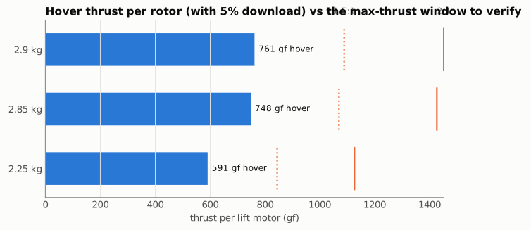
A VTOL carries a whole wing through hover, and it needs control authority on top of holding altitude, so the lift motors want 1.5 to 2 times the weight in maximum thrust. At 2.85 kg that is 1070 to 1425 gf per motor from the 2809 1250KV on 6S with the Gemfan 8041. The class suggests it will get there, which is exactly why it has to be measured.
Numbers for eCalc
Section titled “Numbers for eCalc”xcopterCalc for the lift system: four motors, all-up weight 2850 g, frame “quad”, prop 8 x 4.1 two-blade, a 6S Li-ion pack of 10000 mAh, iFlight XING2 2809 1250KV (or the nearest listed 2809 class), elevation of your field. Compare its hover current (this page says 27.5 A) and its maximum thrust per motor against the 1070 to 1425 gf window.
propCalc for the pusher: T-Motor V3115 640KV, APC 12x8E, 6S, and the thrust points from the table above, 4.0 N (410 gf) at 20 m/s for cruise and 7.6 N (775 gf) at 30 m/s for AIRSPEED_MAX. The pusher must also cover climb, so check that it makes at least 10 N at 15 to 20 m/s.
Full-airframe CFD
Section titled “Full-airframe CFD”The whole external airframe, fuselage, VTOL pods with parked props, landing gear and pusher included, was run in OpenFOAM (RANS, k-ω SST) on dell01 in two rounds (tools/cfd_case.py; the full log with every table is aero/cfd/NOTES.md). Round 1, 2026-09-27, compared the first keel A with and without the tip fins on a coarse mesh (2.85 million cells). Round 2, 2026-09-28, ran the flight configuration, keel A as the foot and no tip fins, on the coarse mesh and on a fine one (4.9 million cells, 1.6 mm cells on the surface features). The coarse mesh is good for lift and drag but not for the lateral derivatives, the pitching moment or the stall, so the figures below are fine-mesh unless marked. The elevons are neutral in the CFD geometry, so these are untrimmed states.
Where the lift and drag are. At 6.7° the aircraft makes CL 0.50 for CD 0.053, an L/D of 9.4. The wing carries CL 0.26, the fuselage 0.13 and the pods 0.11: the bodies make almost half the lift, which the vortex-lattice model cannot see. The drag splits as fuselage 1.06 N, pods and parked props 0.95 N, wing 0.88 N, landing gear 0.56 N and pusher 0.03 N. The fuselage’s share is mostly induced drag on its own lift rather than parasite drag. The gear, CD 0.0085, is nearly twice the 0.0048 in the build-up above and about 15% of the aircraft’s drag; its keels are sized for yaw stiffness the aircraft turns out not to need all of, so a smaller keel is the obvious drag saving.
Stiffer in yaw than the vortex-lattice model said. Fine mesh, flight configuration, per radian: Cn_β +0.033 (vortex-lattice tips off: +0.017), CY_β −0.29. The keel supplies +0.024 of it and the front stilts +0.005, pushed to windward by the crossflow round the fuselage nose; the wing adds +0.009 and the fuselage costs 0.003. Take +0.03 ± 0.005 as the design value until a third mesh level confirms it.
Almost no dihedral effect. Cl_β is −0.003 in body axes and about zero in stability axes, against −0.005 from the vortex-lattice model and −0.035 on the coarse mesh. The swept panel gives the usual stabilising roll, and the drooped winglet tips give almost as much the other way, as anhedral does; the coarse mesh could not resolve the thin droop and also separated the mid-span too early, which exaggerated the effect. So without the tip fins the aircraft barely rolls away from a side gust and does not level itself: the autopilot holds the wings level in every mode it flies, and the spiral mode is set by the roll loop, not the airframe. Hand-flown in MANUAL it would need constant small corrections. What the tip fins contributed to roll was measured only on the coarse mesh, so that number is not trusted.
The Winglet Stabilizers are deleted (decided 2026-09-27). L/D was the same with and without them, and they did not change where the stall starts. The trade the fine mesh adds is the one above: with the fins gone the dihedral effect is close to zero, which is harmless under the autopilot. The drooped Winglet stays as the tip closure, with the stabilizer’s hook rails trimmed flush and sealed.
Pitch through the stall. Stable all the way to 11°, with the margin shrinking:
| α | CL | CD | Cm about the 270 mm CG |
|---|---|---|---|
| 6.7° | 0.50 | 0.053 | −0.059 |
| 8° | 0.58 | 0.062 | −0.066 |
| 11° | 0.70 | 0.102 | −0.070 |
| 14° | 0.77 | 0.161 | −0.080 |
| 17° | 0.84 | 0.228 | −0.096 |
From 6.7 to 8° the neutral point is 22 mm aft of the CG (vortex-lattice: 26 mm). From 8 to 11° the slope is a fifth of that, a margin of about 6 mm on average and probably near zero at 11°. There is no pitch-up, but there is no nose-down break to warn of the stall either: the lift keeps rising while the nose simply stops pushing back. That is the thing to watch in the stall test. Past the stall the stiffness comes back: at 14° (2026-09-28) Cm is −0.080, 0.010 more nose-down than at 11°, a slope of about −0.0035 per degree, while the lift is still rising slowly (CL 0.77, so maximum lift is near 14°). The wing’s own moment grows from −0.13 to −0.17 as separation spreads over the inner elevon span and the lift that remains moves aft. So a stalled TerraHawk drops its nose when the elevons are neutral rather than locking into a deep stall, the answer the stall-test card’s one-second nose-drop check will test in the air. Two cautions on the size: the flow at 14° is unsteady (CL moves by 11% between samples), and separately meshed cases differ by about 3% in Cm, about 0.002 here, which is also why the smaller 8 to 11° change is less certain than it looks. At 17° the trend holds and steepens: Cm −0.096, about −0.005 per degree from 14°, and even the most nose-up sample of that unsteady run (−0.067) stays nose-down. The lift is still rising slowly there (CL 0.84), because the fuselage and pods keep lifting while the wing’s outer panels give up, so the whole aircraft has no sharp maximum-lift point in this range; the wing alone gains only 0.03 from 14 to 17°.
A wing drop past the stall. At 17° the rolling moment swings between about −0.06 and +0.08 with a mean near zero, and the drag split between the two wings changes with it: the separation alternates between the left and the right wing rather than sitting symmetrically. A steady RANS solver can only show that as an oscillation, but in the air it is a wing drop, the classic swept-wing stall behaviour. Its size is about 7 N·m of roll at 20 m/s dynamic pressure, which the elevons can hold at full throw in attached flow but not easily with the inner elevon span separated. So the stall test should expect a roll-off at the break, and recover by unloading (neutral or down elevon to reduce the angle of attack) rather than by rolling against it, which on a stalled wing can deepen the stall on the low side. Low confidence on the size; high on the tendency. The coarse mesh had shown a pitch break near 7°; the fine mesh shows that was its early separation, not the aircraft.
Where the stall starts: at the printed joints of the wing. At 8° the wing is attached except for thin strips at the seams of the printed wing: the outer-panel-to-Winglet joint (X 645 mm), the panel joint (445 mm) and the joint between the inner and outer elevons (480 mm). The last one is partly the model’s: in the kit the two elevons meet flush and are glued into one surface (manual §3.5), while the CFD geometry has them as two separate parts meeting edge to edge, so the strip at 480 mm is less certain than the other two. At 11° the flow is reversed from 380 to 600 mm, starting at 7 to 12% of the chord and deepest at 440 to 500 mm, in the inner half of the elevon span; the wing beside the pods and the tip from 620 mm outward stay attached. That fits the section analysis above, where the whole outer panel reaches its limit together, and it puts the first separation where the seams and gaps are. So sealing them is worth doing: wick thin CA into the panel joint and the Winglet joint and sand them flush, glue the inner and outer elevons as the manual says and sand that seam flush, and run hinge-seal tape along each elevon’s upper hinge line (the print plan’s “Seal the wing seams”; a printed TPU hinge wiper is a later tape-free option). It is the cheapest aerodynamic improvement on the aircraft, and it sits where roll control lives. The round 1 report of separation behind the pods at 6.7° was a mesh artefact (the cells reached into the hollow spar bores); on the outer skin the wing is attached there.
What is not settled
Section titled “What is not settled”Prop and wing interaction. VSPAERO actuator-disk runs for transition (lift rotors at half the weight at 12 m/s) and cruise (pusher only) gave large lift losses. A check with every disk at nearly zero thrust gave the same loss, so it comes from having the disk geometry in the model, not from any slipstream, and those results are left out. The hover download and parked-prop drag above are hand estimates instead. DUST, the open-source mid-fidelity solver from Politecnico di Milano, is built for exactly this, rotor wakes over wings in hover and transition, and is the next tool to reach for.
Elevon effect. The six deflection runs do not lie on one line: the 10° and 15° up runs gave almost the same lift, which a vortex lattice cannot do physically. The fit through all six carries about 0.03 in CL, about 2° of trim at low speed.
The fuselage in yaw. The vortex-lattice model sees the centre body as a thick wing, not a body, so Cn_β here is the optimistic side.
Everything, until it flies. The cheapest checks against a first flight log are the hover throttle (Q_M_THST_HOVER), elevon trim at a known airspeed, and the speed at which Q_assist wakes up.
To do: measure the lift motor and pusher on a thrust stand (max thrust per motor against the 1070 to 1425 gf window, hover current against 27.5 A, pusher thrust at 3 to 10 N) before the first hover.
How it was done, and one trap
Section titled “How it was done, and one trap”| Step | Tool | Output |
|---|---|---|
| Slice the STLs into stations and sections | tools/wing_geometry.py (trimesh) |
aero/geometry.json, aero/airfoils/*.dat |
| Section polars at Re 100k to 750k, Ncrit 7 | tools/section_polars.py (XFOIL 6.99) |
aero/polars/ |
| Build the OpenVSP model, check it against the kit | tools/vsp_model.py |
aero/vsp/terrahawk*.vsp3 |
| Vortex-lattice sweeps and stability derivatives | tools/vsp_analysis.py (VSPAERO 7.2.2) |
aero/vsp/results/*.json |
| Strip-theory drag, trim, stall, performance, figures | tools/aero_report.py |
aero/vsp/results/summary.json, docs/aero/*.svg |
OpenVSP runs in a container from NASA’s Ubuntu build, tools/openvsp/Dockerfile, because the Arch package needs a from-source GCC 14:
docker build -t terrahawk-openvsp tools/openvspuv run --with trimesh --with numpy --with scipy --with networkx --with shapely python tools/wing_geometry.pyuv run --with numpy python tools/section_polars.pydocker run --rm -u $(id -u):$(id -g) -v $PWD:/work -w /work terrahawk-openvsp python3 tools/vsp_model.pydocker run --rm -u $(id -u):$(id -g) -v $PWD:/work -w /work terrahawk-openvsp python3 tools/vsp_analysis.py clean elevon_up elevon_down stabuv run --with numpy --with matplotlib python tools/aero_report.pyTwo OpenVSP details cost real time and are worth knowing. The elevons are modelled by rotating the aft 30% of the section about the hinge in the airfoil files, because VSPAERO’s own control-surface path needs per-surface tag files that the headless geometry step never writes. And OpenVSP already puts both halves of a mirrored wing into the VSPAERO mesh, so turning on VSPAERO’s symmetry option as well stacks image vortices on the real ones. The answers then change with every mesh refinement instead of converging. The first run with that setting happened to land within a centimetre of the manual’s neutral point, which is what made it convincing.
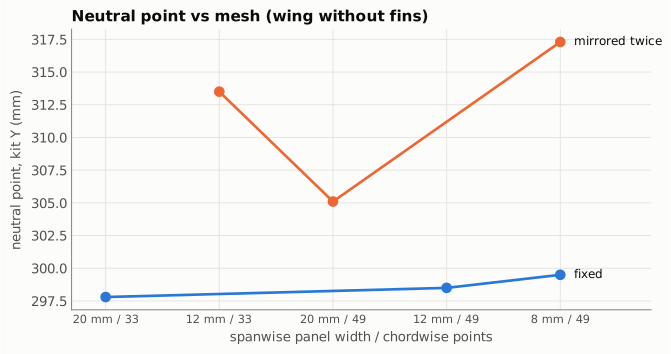
With the fix the neutral point moves less than 2 mm from the coarsest mesh to the finest, and the production runs use the finest (8 mm spanwise panels, 49 points around each section).
Source: docs/aero.md in the repo. Edit it there; this page is generated.
Comments
Comment on the whole page here, or on one section or step with the button beside it.