
Parts
The first build is our own aircraft, Fuselage C v2.4B (Ryan, 2026-10-13). th-blender draws its parts. To find which file to print, use First build parts: it lists every file of the first build with its bed and md5. Do not print a file that is not on that list. th-blender promoted them to parts/ on 2026-10-14 (de83ad68). Each part is shown in the assembly frame, where it fits: X port, Y aft from the nose datum, Z up, in mm. Drag to turn a model.
The masses are th-blender’s estimates: the solid volume times 1.27 g/cm³ for PETG or 1.21 g/cm³ for TPU. So they are higher than a sliced mass. For lightweight PLA (LW-PLA) the table gives the volume only, because th-main’s slice sets its mass. All printing waits for th-main’s Fuselage C bed plan, except bench tools and test prints (Ryan, 2026-10-10 and 2026-10-11).
Fuselage C v2.4B body
Section titled “Fuselage C v2.4B body”Fuselage C is th-blender’s clean-sheet fuselage and wing roots. It is our own work, VTOL Sections included. So its shells are shown here (Ryan, 2026-10-14). v2.4B stretches the forebody 6 mm, so the pitot tip is at Y −30.8. The 3D view uses decimated copies of the shells, with about 12,000 faces each (docs-site/scripts/decimate_shells.py). Print from the files in parts/, not from these copies.
Loading 3D view…
| Shell | Material | Volume | Print face |
|---|---|---|---|
| Fuselage C v2.4B Front | LW-PLA | 720.0 cm³ | Its aft face, Y 255 |
| Fuselage C v2.4B Spar Box | LW-PLA | 340.6 cm³ | Its front face, Y 255 |
| Fuselage C v2.4B Bay | LW-PLA | 619.4 cm³ | Its front face, Y 341.5 |
| Fuselage C v2.4B Tail | LW-PLA | 139.7 cm³ | Its front face, Y 560.1 |
| Fuselage C v2.4B Hatch | LW-PLA | 178.7 cm³ | Its aft end, Y 244.85 |
| Fuselage C v2.4B Canopy (PETG) | PETG, about 24.9 g | 19.6 cm³ | Its aft edge |
| Fuselage C v2.4B VTOL Section, port and starboard | LW-PLA | 297.9 cm³ each | Not stated yet: the slicer’s default is the root face |
Four 20 × 10 × 5 mm N52 block magnets hold the Hatch’s front. A snap catch holds its aft end (the Hatch Catch, below). The Canopy holds on snap features, not magnets, so no magnet is near the GPS or the flight controller (Ryan, 2026-10-11).
Lift ESC on edge
Section titled “Lift ESC on edge”The TBS Lucid 4-in-1 stands on edge across the bay, ahead of the Spar Box (Ryan, 2026-10-13 and 2026-10-14; th-blender 2c6c2dae). Its short side is vertical, and its battery tabs are to starboard. Its component side faces the Spar Box’s open front, 2.15 mm ahead of the front spar. The phase leads are soldered: each triple leaves along the pack-side face as a flat 16 AWG ribbon on a 0.4 mm Kapton-faced spacer. There are no disconnects. Three Rubycon 560 µF capacitors connect at the tabs (th-eda).
Loading 3D view…
| Part | Material | Mass, estimate | Print face |
|---|---|---|---|
| Fuselage C v2.4B Lucid Edge Bracket (PETG) | PETG | 4.6 g | The duct wall’s forward face |
| Lucid Caps Cradle (PETG) (C v2.4B) | PETG | 1.35 g | Its underside |
| Lucid Caps Cradle B (PETG) (C v2.4B) | PETG | 0.90 g | Its trough side; th-blender confirms the face before it goes on a bed |
| Fuselage C v2.4B Lucid Edge Gaskets (TPU) | TPU | 0.14 g, six pieces | Print from the “[print flat]” copy, which lays each piece flat (th-blender 2232f1e4) |
The board in the 3D view is our own model from measured numbers, not TBS’s CAD. The file of the three capacitors has “100uF” in its name for historical reasons: it holds the three 560 µF capacitors. The heat plate is reserved: fit it only if the GNSS or heat tests ask for it.
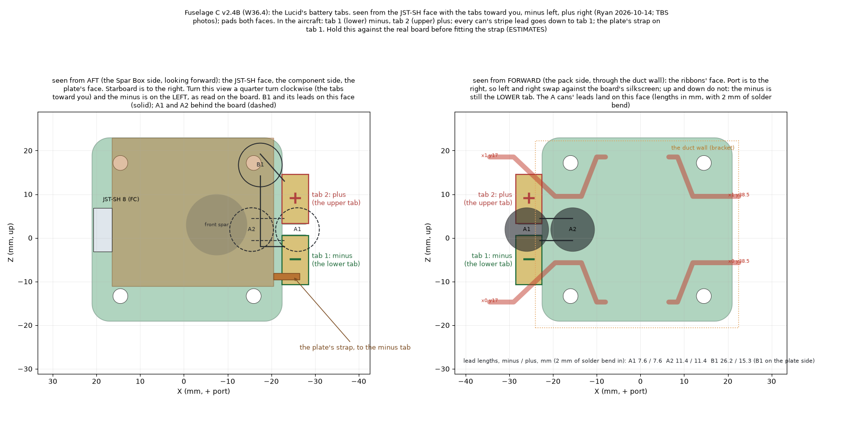
The drawing shows the battery tabs. Tab 1, the lower tab, is minus, and tab 2, the upper tab, is plus (Ryan, 2026-10-14; th-blender 220bd240). Hold the drawing against the real board before you fit the strap.
Q43 seat
Section titled “Q43 seat”Q43 Seat (C v2.4B), PETG, about 9.4 g (estimate). It holds the Q43 NEO-F9P under the radome. The seat is 110 × 70 mm and 3 mm thick, from Y 265 to 335 and Z 23.7 to 26.7. Print it on its underside, with the pocket up. The pocket follows the outline of the copper floor, and the head of each of the three screws up into the Q43 bears on a 1.0 mm ledge in its counterbore (th-blender W46). The 3D view also shows the seat screws.
An FR4 copper floor under the seat is a shield, and it is not optional: it shadows the Q43 from the Lucid. It goes forward to Y 246.9 (th-blender, W36). Use copper or tinned copper only, never nickel EMI tape or steel.
Loading 3D view…
Avionics plate
Section titled “Avionics plate”Avionics Plate (LUX F765) (C v2.4B), PETG, about 14.8 g (estimate; th-blender W46 bridged the port aft post back onto the plate, W55 took off the can’s two rings and the saddle’s dowel holes, and W57.1 added a relief under the LUX’s USB-C and microSD connectors, with 1.55 mm of PETG left under it). It carries the Lumenier LUX F765 flight controller over the front spar, from Y 261.5 to Y 342.5. The Y Lead Cap Saddle (C v2.4B) and the 1000 µF can in the plate’s two rings are retired (Ryan, 2026-10-15): with one Micro BEC for each elevon servo, each can sits at its servo end (th-avionics, th-main f2115545). th-blender’s W55 took the rings off the plate.
Print it on its underside. The 3D view shows the plate’s load as placed, and the USB-C pigtail.
Loading 3D view…
Parts in the Spar Box and the Bay
Section titled “Parts in the Spar Box and the Bay”Loading 3D view…
| Part | Material | Mass, estimate | Print face |
|---|---|---|---|
| Fuselage C v2.4B Rim Frame (PETG), port and starboard | PETG | 7.0 g and 7.7 g | Not stated yet: the slicer’s default is the front face |
| Fuselage C v2.4B Deck Pad (PETG), port and starboard | PETG | 1.6 g each | Its top face, with the insert hole down (the generator). th-main sets the slicer to match |
| Fuselage C v2.4B Hatch Catch (PETG) | PETG | 2.1 g | Its X −22 face |
| Fuselage C v2.4B Beacon Carrier (PETG) | PETG | 20.5 g | Its flat underside, Z −14 |
| M10 Hanger (C v2.4B) | PETG | 9.0 g | The floor’s underside and the tongue, its largest flat face |
The SEQURE M10-25Q is the aircraft’s only compass and its GPS2 (Ryan, 2026-10-15: the SEN0697 cannot be bought; th-avionics f7b6ae3f, e05774a2). It hangs under the Bay roof at X −3, Y 409, with the module’s top at Z 46.4, in the M10 Hanger. The hanger goes on two filament dowels in the roof holes the SEN0697 Hanger used, so the Bay does not change. The hanger is open forward, and the lead leaves forward with a tie across the front and a tongue as its tie point (th-blender W52.1). The Q43’s own compass stays off. Do not print the SEN0697 Hanger.
Parts in the VTOL Sections
Section titled “Parts in the VTOL Sections”Loading 3D view…
| Part | Material | Mass, estimate | Print face |
|---|---|---|---|
| Fuselage C v2.4B VTOL Section Plate (PETG), port and starboard | PETG | 4.5 g each | Not stated yet: the slicer’s default is the outboard face |
| Fuselage C v2.4B VTOL Spar Mount (PETG), port and starboard | PETG | 28.6 g each | On its lean, as before |
| Wire Window Cover (C v2.4B), port and starboard | TPU | 0.40 g each | Not stated yet: the slicer’s default is the outboard face |
| Conduit Seal (C), port and starboard | TPU 95A | 0.89 cm³ each (measured from the STL) | Not stated yet |
The wire window covers close the 11 mm wire window. The VTOL Spar Jig’s 45° land guides the wire slot in the VTOL spar, so the VTOL Slot Guide is retired (Ryan, 2026-10-16). Each conduit seal plugs the mouth of the wing’s wire conduit at the Spar Box joint. A slot and a slit in the seal let it open round the elevon servo lead. The Fuselage C seal fits v2.4B unchanged (th-blender 2232f1e4).
The first build flies our own wing section, with a fence on each wing at X 445 (Ryan, 2026-10-17; th-blender W73 851d43db; th-aeronautics’ confirming runs e21bcc84). The planform, the spar lines, the hinge line and the root are the same as the first design’s. The sections, the camber and the twist are new. Design decisions gives the reasons.
Each part comes as a port file and a starboard file. The starboard file is the exact mirror of the port file, so print the starboard file or mirror the port file on the bed. The view shows the port wing as it flies.
- Wing Inner and Wing Outer (own section). LW-PLA panels. The Outer has a slot at its root for the fence’s tongue. The panels join at X 445 on two 1.75 mm filament dowels, and the fence is held between them.
- Wing Fence (own section, X 445). A PETG plate, 1.2 mm thick. Its tongue goes onto the step of the Wing Inner, and the Wing Outer closes the slot on it. Glue fills the 0.05 mm and 0.15 mm gaps along its root.
- Wing Tip (own section). It closes the outer end of the panel and holds the tip position light. Its light window is the Position Light Window (tip) (own section), a new part cut from this tip. The starboard tip takes the starboard window file.
- Elevon (own section). One part, about 296 mm along the hinge. It fits the Kobra Max standing or flat.
- Servo Mount MD65MG (own wing). It holds the Hitec MD65MG in the Wing Inner’s servo pocket.
- Wing Inner Plate (ours). It closes the root of the Wing Inner against the VTOL Section and holds the catch for the clip, on three 1.75 mm filament dowels.
- Wing Clip (ours). One part in place of the earlier clip and clip base, on two 1.75 mm filament dowels. Its catch height can change after the clip coupon is printed (th-blender W73).
| Part, one side | Material | Mass, estimate | Print face |
|---|---|---|---|
| Wing Inner (own section) (C v2.4B) | LW-PLA | 39.21 g | Its root face |
| Wing Outer (own section) (C v2.4B) | LW-PLA | 21.12 g | Its root face. The fence slot’s ledge is 0.75 mm up |
| Wing Tip (own section) (C v2.4B) | LW-PLA | 7.84 g | Its root face |
| Elevon (own section) (C v2.4B) | LW-PLA | 13.93 g | Its root end, standing |
| Wing Fence (own section, X 445) (C v2.4B) | PETG | 2.28 g | Its outboard face |
| Servo Mount MD65MG (own wing) (C v2.4B) | PETG | 4.32 g | Not settled: its floor, or upside down on its rails (th-main) |
| Wing Inner Plate (C v2.4B, ours) | PETG | 2.27 g solid | Its dry face |
| Wing Clip (C v2.4B, ours) | PETG | 3.54 g solid | Its flat side, so that the arm bends along the layers (th-main sets the slicer to it) |
| Position Light Window (tip) (own section) (C v2.4B) | Clear PETG | 0.07 g solid | Its open inner face |
One wing in LW-PLA is about 82.1 g, against about 80.0 g for the first design’s wing. The masses are th-blender’s slices (W73, W73.1) and are estimates until th-main slices the beds.
Loading 3D view…
Payload covers
Section titled “Payload covers”Two PETG covers close the payload bay from below, from Y 346 to 528 and about 80 mm wide. Five M3 screws hold the cover to heat-set inserts in the Bay’s bosses. Fuselage C v2.4B Payload Cover (blank), about 39.4 g (estimate), closes the bay with no payload. Fuselage C v2.4B Payload Cover (Survey3W), about 39.6 g (estimate), holds the Survey3W lens down. Each cover prints standing on its aft end, from its “[print foot]” copy.
The Survey3W does not fly on the first flights. Whether it returns is Ryan’s decision (the Decisions table).
Loading 3D view…
The Fuselage B TFmini-S cover is not drawn for Fuselage C.
Pitot beside the camera
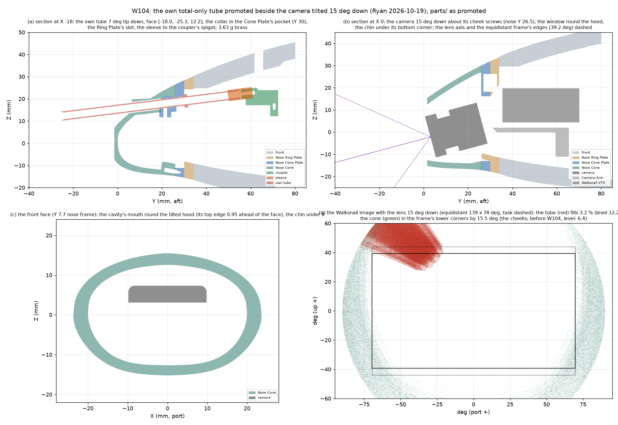
Section titled “Pitot beside the camera”The pitot is our own 4 mm brass tube, total pressure only, beside the camera in the starboard upper part of the nose at X −18, tipped 7° down (Ryan, 2026-10-19; th-blender W104, from the pitot-tube project’s part). Its open face is at (−18.0, −25.3, 12.22). The tube and its two collar slices are brass, cut to the pitot-tube project’s cut list (HANDOFF 3.6), not printed: about 3.63 g in all. The static pressure comes from the two side ports at Y 40, so the tube has no static spigot and needs no plug. It replaced the MS4525’s kit tube on 2026-10-19, which had replaced the pitot on the top centreline (th-blender W75) the same day.
The camera tilts 15° down about its cheek screws, which sit on a turned pair of holes in the Camera Arm (the lens axis is 15° below the airframe’s axis; th-avionics sets the OSD horizon to match). The Nose Cone’s window and chin follow the tilted camera.
The tube rides in the nose cone unit, not in the Front: the cone, its plate and the tube come off forward together. When the cone comes off, the silicone sleeve lets go of the tube and stays on the coupler. The sleeve is the only thing that disconnects, and the cone does it by itself. The union is not reachable with the Hatch open, so after every refit, check the line (build path).
- Nose Cone Plate (C v2.4B, ours) carries a PETG boss round the tube and a pocket in its aft face that seats the tube’s collar. One M2 × 6 thread-forming screw clamps the tube, radially from below at Y 21.5. The plate prints on its aft face; the pocket leaves a small notch, 0.37 mm deep, in the first layer beside the seat bore.
- Nose Ring Plate has a slot that the tube passes through, 1.31 mm clear of it.
- Pitot Coupler (PETG) has a barbed total spigot on the tube’s axis and a 3.4 mm static spigot.
- Silicone sleeve. One straight 11 mm length of 3 × 5 mm silicone: about 5 mm on the tube and 5 mm on the coupler’s spigot, with a 0.84 mm gap.
- Static lines. 1/16 in ID × 1/8 in OD silicone, 284.5 mm in three cuts: 106.7 mm each from the side ports to a barbed tee above the aft end of the airspeed sensor board, then a 71.1 mm trunk down the starboard wall at Y 80 to the coupler’s static spigot from outboard, held once in the PETG Static Line Clip (0.27 g, a 3.3 mm ring with a snap-in mouth, on two filament dowels in the Front’s upper starboard wall; route B, Ryan 2026-10-20). The cut lengths include 4 mm over each port stub and 5 mm over each barb or spigot. The spigot is 3.4 mm, too large for this line, so the trunk’s end goes 3 mm into an 8 mm cut of the 3 × 5 line, which stretches 5 mm over the spigot. With that 5 mm sleeve the trunk’s end stays 3.12 mm from the MS4525 board on route B. The trunk stays 3.16 mm from the pack’s box over the slider’s travel, and the clip’s pad 2.58 mm from it, the nearest part to a wide pack. The port line goes forward of the radio cradle lid’s tab and over the VTX’s top port edge, where the passage under the Front’s wall is 4.6 mm wide: there it is 0.53 mm from the VTX and 0.62 mm from the Front, and 0.73 mm at the port stub’s exit rail. Apart from that point, the port exits and the line over each port stub, every line clears the parts around it by 1.0 mm or more (th-blender W111 c4d7ee16, W111.2 d0d22013, W117.1 88ac2c95; parts list rows 11e, 11f and 11h).
Loading 3D view…
Lights
Section titled “Lights”The night lights do not fly on the first flights. Their parts are drawn and promoted with the rest of v2.4B.
Light Battery Saddle (TPU) (C v2.4B, aft 8, lead forward), TPU 95A, about 3.4 g (estimate). The 2S lighting battery lies flat on top of the flight pack, under the Hatch, with its lead forward. It sits 4 mm further forward than before, because the lights node left the pack top (Ryan, 2026-10-15; th-blender W49). Print the saddle flat on its base.
Loading 3D view…
The lamp parts below are not in the assembly frame. Each set is in its own frame: the landing light’s, the strobe ring’s, and the position light pocket’s. They are the same as the untagged copies already in parts/.
| Part | Material | Mass, estimate | Print face |
|---|---|---|---|
| Landing Light Frame (C v2.4B) | PETG | 7.7 g | Its ledge face, belly side down |
| Strobe Clip Ring (C v2.4B) | Clear PETG | 0.92 g | Its top face, fingers up |
| Strobe Dome Buck (C v2.4B) | PETG | 23.6 g | Its flange face |
| Strobe Plate (C v2.4B) | PETG | 3.1 g | Either flat face |
| Strobe Ring (top) (C v2.4B) | PETG | 4.5 g | Its lip face, skin side up |
| Position Light Window (tail) (C v2.4B) | Clear PETG | 0.14 g | The flat inner face |
The tip window is the Position Light Window (tip) (own section), in the Wing section. It closes the light slot near the leading edge of our Wing Tip, 11.0 mm in from the leading edge at X 662. The LED behind it aims 41.4° outboard of dead ahead and 6.0° below the horizon (th-blender W73.1, W73.2). The second view below shows the port window where it flies, in the port tip; the starboard window is its mirror.
Loading 3D view…
Loading 3D view…
Loading 3D view…
Loading 3D view…
Pusher ESC tray and vent
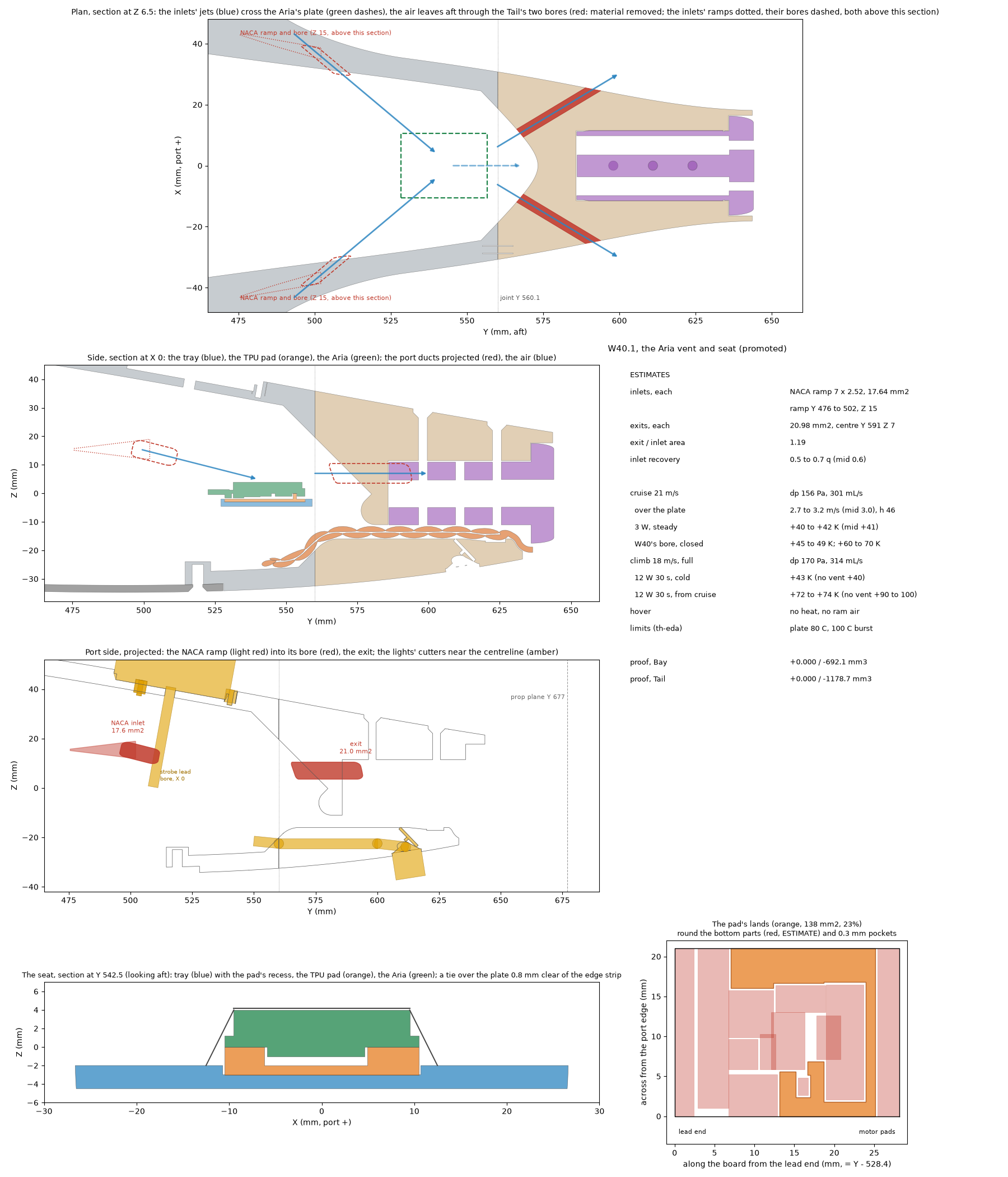
Section titled “Pusher ESC tray and vent”The DYS Aria 70A pusher ESC sits in the Bay from Y 528.4, on the Fuselage C v2.4B Aria Tray (PETG). A TPU Aria Pad seats the board: the board bears on its bare margins, and every part on its underside goes in a pocket (th-eda). The pockets come from photos of the board, an estimate until th-eda measures one. Ties hold the board through slots at X ±12.5 to 14.3 (th-blender W40.1, 756d71bf). The tray’s four filament dowels go into the Bay walls first. The tray then goes up through the payload opening and slides aft onto them in slots, and epoxy holds it (th-blender W46).
The Bay and the Tail carry the Aria vent. On each flank, a NACA-style ramp runs from Y 475.6 to 502.1, centred on Z 15.4. It feeds a bore with a 17.64 mm² throat, and the jets cross the Aria’s plate. The air leaves through two bores in the Tail’s flanks, centred on Y 591.
In cruise at 21 m/s, the plate rises an estimated 40 to 42 K over ambient. With a closed tail it rises 60 to 70 K (th-blender W40.1, estimates). Print the Bay with the Aria Vent Modifier, which th-main’s bed carries.
Loading 3D view…
Keel B landing gear
Section titled “Keel B landing gear”Ryan chose keel B on 2026-09-29 as the build’s landing gear. tools/make_keel_b.py and tools/make_stilt_b.py generate it. Each side has a front stilt under the front motor mount and a rear keel under the VTOL spar, from Y 380 to 520. The aircraft stands 168 mm below the datum.
Each is split at a seam, 52 mm below the datum on both, with no key. Below the seam is a lightweight-PLA blade. Above it is a PETG mount part. The keel’s two glass cores and the stilt’s carbon core run 22 mm up into blind bores in the PETG mount part (Ryan, 2026-10-06; th-blender 9e1eeeb, cfe1230).
The mount parts are grown from the kit’s VTOL Motor Mount, so this page shows no 3D view of them. The blades end at the seam.
The keel sole carries the gold charging plate. The grey ghosts are the glass cores.
These are review outers: solid shapes for review, not the parts to print.
Loading 3D view…
The Landing gear page has the parts table, the section, the seam and the masses.
Nose package
Section titled “Nose package”The nose package is the first build’s nose (Ryan, 2026-10-05; th-blender 1dbefba and 7bcbbd8). Its files are in the nose frame: Fuselage C v2.4B moves them 6 mm forward (th-blender W69).
- Nose Cone (C v2.4B, ours) and Nose Cone Plate (C v2.4B, ours). These are our own parts. They are drawn from their function and from the parts that they touch (th-blender W44, promoted in W69 4a7d6edf). The cone comes off at Y 36. Five pairs of 8 × 3 mm N52 magnets hold it (nose rev C; th-main 1553cf06). Four cut 1.75 mm filament dowels join the cone to the plate: 3 mm in the plate and 5 mm in the cone. The cone has a flat front face with cheeks for the Walksnail Avatar HD Moonlight camera. The cheeks are cut on a line at 71° from the lens axis, so the camera sees 70° to each side (Ryan, 2026-10-17; th-blender W70). The pitot is not in the cone: it sits on the top centreline in its saddle, and the cone slides off under it (th-blender W75). So the cone’s upper skin is symmetric, with no exit bump for the pitot (th-blender W76).
- Nose Ring Plate. The fixed nose ring is part of the Fuselage Front. The PETG ring plate carries the other magnet of each pair and glues to the ring.
- Camera Arm on a riser of Battery Tray B. It carries the Walksnail VTX.
- Glue joints. Every glued joint, PETG-to-LW included, takes cut 1.75 mm filament dowels (Ryan, 2026-10-06).
The Nose Ring Plate, the Camera Arm and Battery Tray B are cut from the kit’s nose plate or tray. So this page shows no 3D view of them and offers no files.
| Part | Material | Mass, estimate | Print face |
|---|---|---|---|
| Nose Cone (C v2.4B, ours) | LW-PLA | About 3.60 g sliced (estimate, th-blender W76) | Its aft face, with the tip up |
| Nose Cone Plate (C v2.4B, ours) | PETG | 6.0 g solid | Its front face, with the magnet pockets up |
Loading 3D view…
Pusher motor mount
Section titled “Pusher motor mount”Pusher Motor Mount (C v2.4B, ours), PETG, 27.9 g solid and about 17.9 g sliced (estimate, th-blender W69). It is our own part (th-blender W44, promoted in W69 4a7d6edf; on bed g11, th-main daa48e07). It is a square tube that goes into the square opening in the Tail, and eight crush ribs make it a tight fit. The EMAX ECO II 3115 attaches with four screws through its four 3.29 mm holes on the 19 mm bolt circle. Two M3 × 30 flat-head lock screws go through the Tail at Y 598 and Y 624 into its 2.5 mm pilot holes. A notch lets out the motor leads, and a groove holds the lead grommet. Print it on its motor face.
Loading 3D view…
Telemetry radio cradle
Section titled “Telemetry radio cradle”These cradles are drawn for the Fuselage B avionics plate. th-blender places them on Fuselage C.
Radio Cradle Base (XIAO) and Radio Cradle Lid (XIAO), PETG, 1.44 g and 1.29 g, from tools/make_radio_cradle.py (reviewed by Ryan, 2026-10-04). They hold the telemetry radio, a Seeed XIAO ESP32-S3 with the Wio-SX1262 LoRa module. The lid presses the Wio-SX1262 onto the XIAO, so the board-to-board connector cannot come apart. The cradle uses no hardware: the lid snaps onto the base, and two printed snap pins click the base onto the plate.
The board model in the viewer is Seeed’s own CAD, placed in the cradle and simplified, shown with Ryan’s agreement (2026-10-04). Seeed publishes the original files with the Wio-SX1262 with XIAO ESP32S3 kit.
Loading 3D view…
Radio Cradle (mR900-30), PETG, 2.77 g, from tools/make_mr900_cradle.py (Ryan, 2026-10-05). It holds the alternative telemetry radio, a Matek mR900-30, with the same two snap pins. The board model is our own, drawn from Matek’s product photos, so its heights are estimates.
Loading 3D view…
Earlier designs
Section titled “Earlier designs”These parts belong to earlier designs, Fuselage B and before, and the first build does not print them. Their files stay in parts/, and the git history of this page has their 3D views.
| Part | Status |
|---|---|
| Survey3 Belly Mount and the cut Fuselage Mid | Retired 2026-10-03: the Survey3W moved to a payload cover |
| Charge Power Bracket and Charge Sense Floor Tray | Drawn for Fuselage B’s battery bay. The first flights have no charge node |
| TFmini-S Belly Mount, TFmini-S payload cover, lid and bezel | Withdrawn 2026-10-05, and the cover is not drawn for Fuselage C |
| Lift ESC Cradle (belly) and Pusher ESC Tray (belly) | Fuselage B. The Lucid now stands on edge, and the Aria sits on the v2.4B Aria Tray |
| Q43 Seat [spine] and Light Battery Saddle (TPU), untagged | Fuselage B. The v2.4B seat and saddle replace them |
| Keel A, with its antenna cassette | Retired from the beds 2026-10-11: the first build prints keel B |
| Fuselage C v2.3 parts | Superseded by v2.4B. The v2.3 Aria Tray is replaced by the v2.4B Aria Tray and Pad (W40.1) |
| The first design’s wing panels, flat tip, elevon, servo mount, Wing Inner Plate, clip and clip base, and the tip window cut from that tip | Replaced by our own-section wing (Ryan, 2026-10-17; th-blender W73). The beds change to the new parts when th-main re-beds them |
Comments
Comment on the whole page here, or on one section or step with the button beside it.