
Landing Gear
Ryan chose keel A on 2026-09-27. Each side has a 20 mm front stilt under the front motor mount and
a 140 mm rear keel from Y 380 to Y 520 on the VTOL spar line (X ±190). All parts land on the hangar
pad’s ground line at Z -168, in the kit frame (X port, Y aft of the nose datum, Z up, mm).
th-aeronautics set the shape (docs/aero.md, “A rear keel instead of rear stilts”). th-hangar set
the pad interface: the soles, the FR4 contact plates and the pin layout. The earlier 28 mm stilts in
docs/stilts.md are superseded.
Generated by tools/make_keel.py, which reuses the stilt builders in tools/make_stilts.py. The
renders are 13-on-keel-a* and 15-detail-keel* in blender/renders/, and scene 13 On Keel A
in the Blender build.
| Part | Material | Qty | File | What it does |
|---|---|---|---|---|
| Keel Shell | LW-PLA | 2 | parts/Keel Shell.stl |
The keel’s skin, printed with one wall. Its top follows the spar and the rear mount |
| VTOL Motor Mount Rear (keel) | PETG, 3 walls, 30 % gyroid | 2 | parts/VTOL Motor Mount Rear (keel).stl |
Grown from the kit’s rear VTOL Motor Mount: the kit mount with its foot blade removed and the keel’s root grown out of it, flush with the shell sides, with the rear core’s 22 mm bore |
| Keel Spar Saddle | PETG | 2 | parts/Keel Spar Saddle.stl |
Cradles the spar at Y 424 to 442, held by two zip ties |
| Keel Sole | PETG | 2 | parts/Keel Sole.stl |
30 x 140 mm skid, 2.5 mm bottom edge radius, plate recess, keel rail on top, and a heel at the rear with a vertical push face at Y 520 |
| VTOL Motor Mount Front (stilt) | PETG, 3 walls, 30 % gyroid | 2 | parts/VTOL Motor Mount Front (stilt).stl |
Grown from the kit’s front VTOL Motor Mount in the same way, with the stilt’s root and core bore |
| Front Stilt Fairing | LW-PLA | 2 | parts/Front Stilt Fairing.stl |
8 x 20 mm section over the core |
| Front Stilt Sole | PETG | 2 | parts/Front Stilt Sole.stl |
30 x 30 mm, 2.2 mm lead hole, and a toe at the front with a vertical push face at Y 53 |
| Keel cores | 6 x 4 mm pultruded E-glass tube | 4 | cut to the reference STLs | Keel front 137 mm, keel rear 125 mm. E-glass, not carbon, so no conductor lies beside the keel antennas (th-aeronautics, 2026-09-27) |
| Front stilt cores | 6 x 4 mm pultruded carbon tube | 2 | cut to the reference STL | 125 mm |
| Contact plates | 1.6 mm FR4, ENIG | 4 | parts/Keel Contact Plate (reference).stl for the 23 x 133 mm rear outline |
th-hangar’s and th-eda’s parts |
| Zip ties | 2.5 mm nylon | 4 | Two per saddle, round the spar |
Left and right are the same prints: the parts are symmetric across X. Every contact plate is one charge pad with a 2.2 mm lead hole. No CAN goes through the feet (th-avionics, 2026-09-27): the docked “site clear” signal travels as 12 V on the charge pads.
The keel is 8 mm thick. Its section has the NACA 4-digit nose back to 30 % chord, holds the full 8 mm back to Y 500, then closes on the NACA tail. A plain NACA section on a 140 mm chord is only about 5 mm thick at Y 484, where the rear core has to sit under the mount. The flat middle gives 0.9 mm of wall over both cores at every height, checked by the generator.
The leading edge rakes back from Y 380 at the top to Y 392 at the sole. The sole’s front corners have a 12 mm radius, so a skid sliding into the trough has no square corner to catch.
The top of the keel is cut by the real spar and rear mount. Ahead of the mount it cradles the spar underside (Z -21.2). Under the mount it gives way to the mount’s own root.
The keel is the foot (Ryan, 2026-09-28; th-aeronautics and th-hangar agreed). The kit’s four lift-motor
mounts (VTOL Motor Mount.stl) are replaced by two parts that carry the foot themselves. Each is the kit mount with its foot
blade cut off below the pad (Z -24.2). A root grows out of the body in its place: 8 mm thick, flush
with the shell or the stilt fairing, flaring along the old blade’s footprint under the mount, and
down to Z -62. There is no collar, no cross pin and no glued blade joint. The landing load goes up
both cores: the front core into the saddle and the spar, the rear core into the root, the
mount body and the spar sleeve. Each core sits in a 22 mm blind bore, three core diameters deep, which
is th-aeronautics’ minimum. The vertical M3 bolt through the sleeve and the spar is an M3 x 25 that
self-taps into a 2.5 mm pilot in the root, down to Z -31.5, with no nut. The kit’s hole there is a
blind 3.1 mm clearance hole with no room for a nut. The charge lead runs up the core, then through a 2.2 mm channel
in the root and the body to the sleeve’s mouth by the spar tip, where the phase leads go into the
spar. No lead is exposed under the mount. The rear mount also has a 3.2 x 6 mm slot for two RG316
leads, the port keel’s ELRS antenna and telemetry coil: from the sleeve’s mouth down and forward through
the root, under the bolt’s tip and ahead of the rear core, out of its forward face into the keel shell
at about Y 462. It has at least 2.4 mm of wall to the bolt and the core.
The old collar was a fuse: in a crash it broke before the mount. With the foot merged, a hard enough side load costs a mount instead. A shallower bore with a bonded core would bring a fuse back, but that is Ryan’s decision.
The front stilt is the 28 mm stilt at a 20 mm chord: 8 mm on 20 mm, with the core at 30 % chord (Y 64) and the sole centred on the mount (Y 68), where the pins are. Its root starts in the stilt’s 8 x 20 section at the fairing top (Z -62) and grows to 12 x 30 in the next 5 mm, then flares along Y under the mount. The growth is for a slope landing: with one sole down first, a side load of about 110 N at the sole makes 13 N·m at the root (th-aeronautics, 2026-09-28). In the 8 x 20 section, the mouth of the core bore would see about 155 MPa; at 12 x 30 it sees about 49 MPa, inside printed PETG. The root is a small bulb in the rotor downwash.
Push faces
Section titled “Push faces”The hangar pad is flat (Ryan, 2026-09-28). After touchdown, two pairs of push bars move the aircraft onto the pin blocks. The along-box bars push forward on the rear end of each keel sole and aft on the front of each front stilt sole, 3 to 23 mm above the pad (Z -165 to -145). The keel’s tail and the stilt’s nose are thin LW-PLA there, so each sole has a PETG push face in that band:
| Face | Where | Shape |
|---|---|---|
| Keel heel | Y 520, on the rear end of the Keel Sole | The keel section from Y 508 to 512, then a 4 mm wide bar to Y 520, up to Z -144.5. The shell’s tail stops at Y 508 below Z -144.3 |
| Stilt toe | Y 53, on the front of the Front Stilt Sole | The stilt’s nose section brought forward from Y 58 to Y 53, up to Z -144.5. The fairing starts above it |
The generator casts rays into each face across the band and stops if the face is not flat and continuous. The across-box bars push on the outer faces of the keel shells and stilt fairings (X 194) at Z -143 to -123 with about 5 N; those faces are LW-PLA and are not changed.
Contact plates
Section titled “Contact plates”The keel sole has a 2.5 mm radius all round its bottom edge, so a keel that lands inboard of the trough lip slides back across it sideways (th-hangar, 2026-09-27). The rear plate sits on the flat inside that radius: it follows the sole outline inset by 3.5 mm, so it is 23 x 133 mm with rounded ends. The generator checks every pad pin (two rows at X ±7, Y 0, ±28, ±56 about Y 450, th-hangar’s layout for this plate) with the aircraft anywhere within ±2 mm: the closest pin edge is 1.5 mm inside the plate. The front plate is 28 x 28 mm, as on the stilts, over six charge pins at X ±8, Y 0 and ±11. The generator checks it the same way: at the ±2 mm limit a pin reaches 13.75 mm from the foot centre, inside the plate’s 14.0 mm. th-hangar owns the pad layout.
Antenna cassette
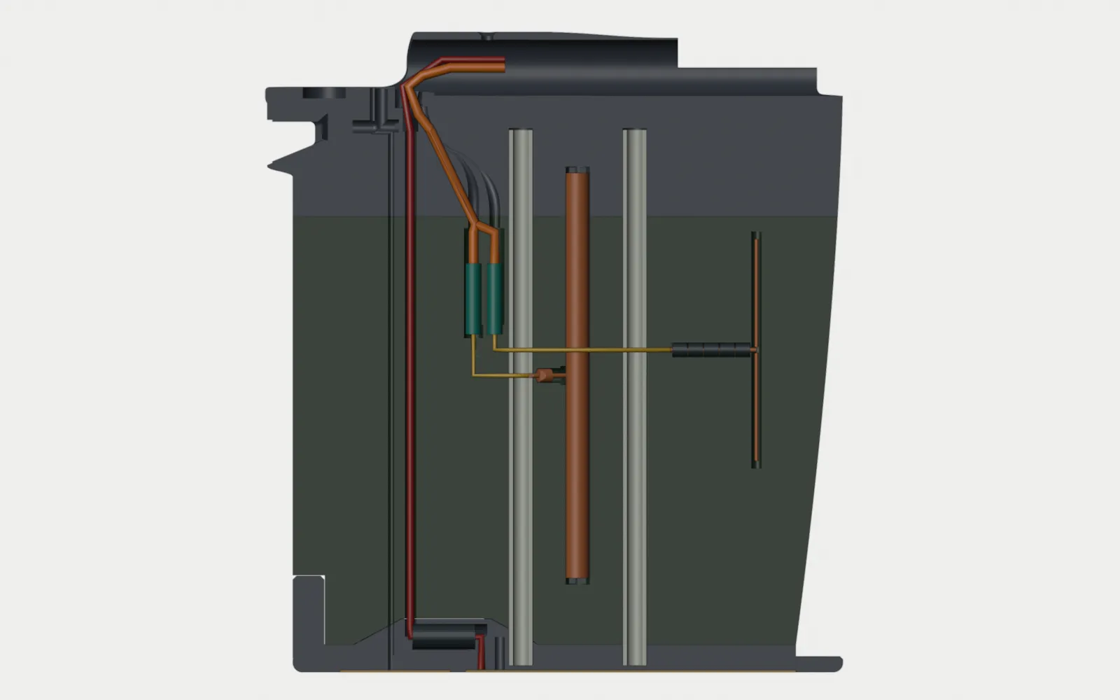
Section titled “Antenna cassette”Each keel B holds one ELRS dipole and one LoRa coil (two-radio diversity, Ryan, 2026-10-06). The port
and starboard keels use the same files. Print the starboard parts mirrored. th-telemetry made the layout
with NEC2 (tools/keel_b_antennas_nec.py, 51c02c6). tools/make_gear_b_print.py makes the parts. The
values below are for the port keel, in the assembly frame.
| Item | Value |
|---|---|
| ELRS dipole | Y 402, centre fed at Z -86. Two arms of 1.0 mm copper or brass wire, 27.4 mm each. Trim on the VNA |
| LoRa coil | Y 447.5, between the glass cores (Y 433 and 462), Z -144 to -41, fed at Z -92.5 on its aft side. 20 AWG enamelled copper wire (0.85 mm over the enamel, row 16n) wound in the groove of the LoRa Coil Former (grooved): the port former in the port keel, the starboard former (a left-hand helix) in the starboard keel (th-blender 6dc7468). Trim on the VNA by quarter turns at each arm’s anchor end |
| Ferrite beads, Fair-Rite 2661000101 | Five on the ELRS pigtail (Y 403.5 to 423.5). One on the LoRa pigtail, at the aft end of its 7.7 mm pocket. Since W116.1 the pocket turns 22 degrees inboard from its forward end (X 190, Y 450.3), so the coax goes past the rear core with no bend (th-telemetry’s NEC2 case k-w116a, bcd69d91). The pocket’s aft end is at X 187.1, Y 457.4. The pocket stops 0.9 mm of LW-PLA short of the rear core’s bore. One bead does the job of two in NEC2 and leaves the feed joint about 4.7 mm between the former’s aft face and the bead, in a slot Z -95 to -90 (th-blender W18; th-telemetry 36af7f0) |
| MMCX jacks, joint J1 | Vertical bays as drawn in W116.1: ELRS at Y 468.6, Z -78.6 to -60.6. LoRa at Y 474, Z -82 to -64. The parts changed (2026-10-22): the jack is the Fairview FMCN5182, an end-launch solder jack (body 4.45 mm diameter, 4.50 mm long, with a 0.70 mm pin and two ground legs 3.00 mm out of the back; 7.50 mm overall; no nut, so the bay holds it by its body), and the plug is a generic MMCX crimp plug for RG316 (row 16c; its knurled part is 4.0 mm diameter, 18 mm long). Mated, the pair is longer than the 18 mm bays were drawn for (about 22.5 mm from the jack’s face to the ferrule’s end, ESTIMATE). th-blender’s W131 resizes the bays. Do not print g17 and g18 until W131 is approved |
| Pigtails, 1.13 mm micro-coax, jack foot to feed | ELRS 73 mm, LoRa 32 mm. Every bend is 6.8 mm or more (W116.1; CAB.697’s minimum, th-telemetry 58575840). Both go inboard of the rear core at X 186.1 in one blister on the lid. The ELRS pigtail also goes inboard of the coil and the front core. The LoRa pigtail does not go around the rear core. The blister keeps 1.0 mm of lid around the grooves and the bead pocket. It is up to 1.7 mm proud, with 4:1 slopes forward, up and down and an 8:1 ramp aft that ends at Y 475.6 (W116.2, th-aeronautics) |
| RG316 | Each cable goes straight up from its plug, bends aft (R 16 or 14.7), then bends up and forward through the mount part (R 12.9) past the spar’s end (Y 486) and forward in the spar (W116.1). Every bend is 12.7 mm or more. The two cables are side by side across the keel (X +-1.33). Over the last bend they move apart to X +-2.9, so they go one on each side of the kit mount’s M3 spar screw at Y 470.5 |
| Charge lead | Its own channel at Y 490. One bead (Fair-Rite 2643250302) in a boss on the sole. No bead at the top (th-telemetry, ed35fde) |
| Lid screws | Four M2 countersunk, brass or nylon: three M2 x 6, one M2 x 5. Do not use steel near an element |
The lid is the inboard half of the keel in the antenna area. It splits from the blade on the centre plane (X 190). The lid and all its antennas come out inboard as one unit. The jack bay stays below the seam at Z -52. There is 5.6 mm (ELRS) and 9 mm (LoRa) of free RG316 above the plugs. Disconnect the MMCX plugs when you remove the lid. Do not use tape or hot glue on the lid (Ryan, 2026-09-28).
Keel A cassette
Section titled “Keel A cassette”Keel A’s cassette is kept here for reference. Keel B replaces it.
th-telemetry gave the antenna sizes and the ferrite beads on 2026-09-28. The jack and bead pockets are
keep-outs until the part drawings are available. tools/make_antenna_cassette.py makes the parts.
The front core at Y 433 goes through the full height of the keel. Its bore leaves 0.9 mm of shell on each side, so no coax can go past it in the 8 mm section. The ELRS dipole (Y 402) is forward of the core. The coax exit from the rear root (Y 462, Z -49) is aft of it. In the port keel, the LoRa coil (Y 448 to 454) is also between the exit and the dipole. Thus the ELRS pigtail goes inboard of the coil and the core, in a blister on the inboard face (Ryan, 2026-09-28).
| Part | Material | Qty | File | What it does |
|---|---|---|---|---|
| Keel Shell (antenna bay) | LW-PLA | 2, one mirrored | parts/Keel Shell (antenna bay).stl |
The keel shell with a pocket in its inboard face and grooves for the elements and the jacks |
| Antenna Cassette Lid | LW-PLA | 1 | parts/Antenna Cassette Lid.stl |
Port lid: holds ELRS B, the LoRa coil, two jacks and two pigtails |
| Antenna Cassette Lid (ELRS only) | LW-PLA | 1, mirrored | parts/Antenna Cassette Lid (ELRS only).stl |
Starboard lid: holds ELRS A, one jack and one pigtail |
| SiK Coil Former | PETG | 1 | parts/SiK Coil Former.stl |
The 4.4 mm core of the LoRa coil. It prints on its flat, and the flat sits on the lid |
| M2 x 6 countersunk screw | Brass or nylon. Do not use steel | 6 | Three for each lid, into 1.6 mm pilots in the shell. Steel near a dipole changes its tuning (th-telemetry) |
The lid is the inboard half of the keel in the antenna area. It splits from the shell on the centre plane (X 190). Each element and each jack is half in the lid and half in the shell. Thus the lid and all its antennas come out inboard as one unit. The lid meets the root above the jacks, so the RG316 does not catch on the shell when you remove the lid.
The antennas (th-telemetry, 2026-09-28):
| Antenna | Construction | Groove |
|---|---|---|
| ELRS dipole | Two arms of 1.0 mm copper or brass wire, 27.4 mm each, 56.4 mm overall, fed at Z -86. Trim on the VNA | 2.7 mm, with 2 mm of trim length past each tip |
| LoRa helical dipole | 0.8 mm enamelled wire, about 4.8 turns per arm, on the SiK Coil Former, fed at Z -92.5. Trim turns on the VNA | 6.2 mm. The former has a wire anchor slot at each end and a 1.2 mm hole at the feed for the wire ends |
| MMCX jack | Fairview FMCN5182, MMCX jack, end launch, solder (row 16d) | Held by its body in a printed bay, its flat base as the key; the pigtail is soldered to its pin and legs (W131) |
| Ferrite beads, Fair-Rite 2661000101 (61 material, 3.51 mm OD, 3.25 mm long) | Five on the ELRS pigtail, directly aft of the feed (Y 403.5 to 423.5). Two on the LoRa pigtail, directly aft of the coil (Y 454 to 461) | 3.8 mm pockets, 20 mm and 7 mm long, in both lids for the ELRS beads. 1.6 mm of wall or more |
The MMCX jacks are vertical, directly below the coax exit: ELRS at Y 462, LoRa at Y 468. On the 45 degree line of the exit, the jacks would hit the LoRa coil. Each pigtail goes from its jack to its feed and leaves the feed at 90 degrees to the element: ELRS horizontal at Z -86, LoRa horizontal at Z -92.5.
| Item | Value | Status |
|---|---|---|
| Pigtail, 1.13 mm micro-coax | ELRS 72 mm, LoRa 30 mm, jack foot to feed | Confirmed by th-telemetry: about 0.3 dB at 2.4 GHz |
| Blister on the inboard face | 1.18 mm high, Y 428 to 456 at Z -86, each end ramped at 1:4.2 | Accepted by th-aeronautics (2026-09-28): the ramps stop a step at the front from tripping the boundary layer |
| ELRS pigtail to the LoRa coil and to the front core | 0.34 mm, surface to surface | Kept. NEC2 (th-telemetry, 7bbdf40): a 4 mm gap gives less than 1 dB. Current on the pigtail shield is the problem: without beads, the LoRa-to-ELRS isolation is -15 dB; with the three beads it is -26 dB |
| Lid screws | 4.0 mm through the lid, 2.0 mm of thread in the shell, 0.8 mm of skin behind each pilot | Put a drop of thin CA in each pilot to make the LW-PLA thread harder |
| Thinnest outboard wall | 0.90 mm at the LoRa groove, 1.94 mm at the ELRS groove, 1.30 mm at the jacks | Checked by the generator |
| Mass, port, shell and lid against the plain shell | +3.8 g, sliced | Antennas, former, screws and coax not included |
Three M2 screws hold each lid. Do not use tape or hot glue (Ryan, 2026-09-28). The screws are where the
keel is 8 mm thick, clear of the cores, the coil and the pigtail. Each hole is 5.35 mm or more from an
element. The screw at Y 422 holds the forward part
of the lid. The aircraft RG316 ends at the plug below the exit (th-main recorded the cut lengths in
docs/agent-threads/harness/). Open points: the jack pocket and the bead pockets, after the part drawings are available.
The printed parts are sliced masses: PrusaSlicer 2.9.6 with the project’s Core One+ presets
(slicing/config/), LW-PLA at 0.60 flow and 1.24 g/cm³, PETG at 3 walls and 10 % gyroid and
1.27 g/cm³, except the two mounts at 3 walls and 30 % gyroid. Each mount is given net of the kit
mount it replaces (13.4 g sliced). None of the parts needs support in its print orientation. Foaming changes volume, not
mass, so the filament fed is the part’s weight. tools/make_keel.py reslices them on every run.
The cores (E-glass in the keel at 2.0 g/cm³, carbon in the front stilts) and the FR4 plates are
estimates from their volumes.
| Item | Per keel | Per front stilt |
|---|---|---|
| Shell or fairing (LW-PLA, sliced) | 16.9 g | 2.1 g |
| Mount with root, net of the kit mount (sliced) | 5.8 g | 7.4 g |
| Spar saddle (sliced) | 1.6 g | |
| Sole (sliced) | 13.5 g | 3.9 g |
| Cores (estimate) | 8.2 g | 3.0 g |
| FR4 plate (estimate) | 11.0 g | 2.8 g |
| Total | 56.9 g | 19.2 g |
Both sides come to 152 g over the kit mounts, against th-aeronautics’ 164 g (55 g per keel, 27 g per stilt). Add a few grams per side for glue, zip ties and leads. Weigh the first set.
The front stilt sole prints plate-recess down. Its recess leaves a 0.8 mm rim, so its bottom edge has a 0.2 mm chamfer instead of 0.8 mm; with 0.8 mm the part would not touch the bed at all. The rim is narrow, so print it with a brim.
Keel B and front stilt B
Section titled “Keel B and front stilt B”Ryan reviewed keel B on 2026-09-29 and chose it over keel A’s shape, with the spar wrap kept, as the split build: an LW-PLA blade on a PETG mount part at a flush seam. The single print in PETG costs about 110 g all-up once the nose ballast follows it, against about 3 g for the split (th-aeronautics).
On 2026-09-30 Ryan chose plain roots for keel B and front stilt B. The flare from the blade into the
mount is gone. The coarse CFD shows a 4.2 % decrease in whole-aircraft drag against the flared roots (CD
0.05858 against 0.06116). Most of the decrease is at the front stilt (-0.0015), then the keel (-0.0006)
and the pods (-0.0003). The results are in docs/agent-threads/airframe-design/ (th-aeronautics,
021e947).
The design protocol (docs/design-protocol.md) has the gates that follow; th-aeronautics keeps the
idea card and the report in docs/agent-threads/airframe-design/. The parts below are review
geometry: solid outers. The printable parts, with the core bores, the bolt pilots and the antenna
cassette, are in “Printable gear B” below.
Generated by tools/make_keel_b.py, tools/make_stilt_b.py and tools/make_wing_tip.py; the
scene is 16 On Keel B in the Blender build. The flared review parts are in parts/ with the suffix
[flared] (make_keel_b.py --profile s --suffix " [flared]", make_stilt_b.py --flared --suffix " [flared]"). They are not for the build.
| Part | Material | File | What changes from keel A |
|---|---|---|---|
| Keel B Blade (split) | LW-PLA | parts/Keel B Blade (split).stl |
The blade below the seam at Z -52. It has no key, because the two cores cross the seam. The section goes straight up to the seam, with no flare |
| Keel B Mount (split) | PETG | parts/Keel B Mount (split).stl |
The kit rear mount, with a half-sleeve round the bare spar and the kit sleeve (16 mm and 20 mm wide, flat top at the spar centreline). A 3 mm fillet joins the blade to the half-sleeve and to the pad. A tapered sleeve covers the full spar from Y 422 to 460 (radius 7.6 mm to 9.1 mm), so the front edge of the kit collar is not a step. The kit foot blade and its fillet go. The part goes down to the seam at Z -52 |
| Keel B Sole | PETG | parts/Keel B Sole.stl |
20 mm wide with elliptical canoe ends (30 mm at the nose, 40 mm at the tail, 4 mm flat ends), 2.5 mm bottom radius, two 8 mm wide brass strips in their own 0.5 mm recesses for one row of eight pogo pins (the flight-pack segment at Y 392 to 476, the L segment at Y 480 to 508, refer to “Keel B contacts”), the 4 mm heel bar |
| Front Stilt B Blade and Mount (split) | LW-PLA and PETG | parts/Front Stilt B Blade (split).stl, parts/Front Stilt B Mount (split).stl |
Keel A’s 20 x 8 mm stilt section, straight up into the kit front sleeve, with a 3 mm fillet at the pad. Split at the same seam, Z -52. From the seam up, the section is 10.4 mm thick, not 8 mm, and the change is eased over the 10 mm below the seam. Chord unchanged |
| Front Stilt B Sole | PETG | parts/Front Stilt B Sole.stl |
16 mm canoe, Y 53 to 83, the toe at Y 53, no plate: charging moved to the keel plates (th-hangar, 2026-09-29) |
| Wing Tip (flat) | LW-PLA | parts/Wing Tip (flat).stl |
Our own tip: the panel’s tip section on the kit’s raked planform, no droop, no crest. --dihedral N bends it up from X 665 |
Section. A NACA modified four-digit thickness form: 9.0 mm at 35 % chord, no plateau, a cubic taper to a 0.8 mm trailing edge, 6.4 % thick at the top chord and 7.0 % at the rail. The section is 7.4 mm or thicker, the least a 6.2 mm core bore with 0.6 mm walls needs, from Y 398 to 469 at the top, so the rear core moves from Y 484 to Y 462 (7.9 mm there) and the front core stays at Y 433 (9.0 mm).
| Sliced mass, one side (solid review outers, seam at Z -52) | Keel B | Keel A |
|---|---|---|
| Blade, LW-PLA | 13.5 g | 16.9 g shell |
| Mount part over the kit mount, PETG | 19.6 g | 7.4 g |
| Keel sole, PETG | 9.5 g | 13.5 g |
| Front stilt blade, LW-PLA | 2.0 g | 2.1 g fairing |
| Front stilt sole, PETG | 2.5 g | 3.9 g |
The front stilt’s mount part weighs 0.3 g less than the kit front mount, because the kit foot blade goes.
The blade’s mass is the review outer sliced with one wall and 4 % infill, an upper bound for the hollow shell that replaces it.
Printable gear B
Section titled “Printable gear B”Ryan gave the go on 2026-10-06. tools/make_gear_b_print.py cuts the review parts above into the
parts that print. The generator does not change the review parts. Print one set at the port side and
one set mirrored for the starboard side.
The seam is at Z -52 (Ryan, 2026-10-06). At Z -30 both glass cores ended in the LW-PLA blade, and the
one-wall blade failed th-aeronautics’ seam check (docs/agent-threads/airframe-design/, 6cb9335). The
spar is 7 mm above Z -30, so a 22 mm blind bore for each core needs the lower seam. The keel cores and the stilt core now
end at Z -30, 22 mm into PETG. Keel B passes with a margin of 5 or more on the cores. Front stilt B
passes with a margin of about 2.3, with its 10.4 mm root.
| Part | Material | File | What it adds |
|---|---|---|---|
| Keel B Blade (antenna bay) | LW-PLA, one wall | parts/Keel B Blade (antenna bay).stl |
Core bores, the cassette pocket on the inboard face, the charge-lead channel at Y 490, the L lead’s 1.6 mm channel at Y 495, the RG316 slot, the notch over the bead boss, and the cut over the sole’s heel. The two RG316 channels (W116.1) |
| Antenna Cassette Lid (keel B) | LW-PLA | parts/Antenna Cassette Lid (keel B).stl |
The same lid for both keels: ELRS dipole at Y 402, telemetry coil at Y 447.5, jacks at Y 468.6 (Z -78.6 to -60.6) and 474 (Z -82 to -64), the blister over the pigtails’ pass (W116.1). Four M2 countersunk screws, brass or nylon (three M2 x 6, one M2 x 5). Never steel |
| Keel B Mount (cable riser) | PETG | parts/Keel B Mount (cable riser).stl |
Two 22 mm blind bores for the cores, the top of the coil’s column, the two RG316 channels up into the spar’s end (W116.1), a cable chamber over the seam and a riser for the charge lead into the kit mount’s bore behind the spar’s end stop, the L lead’s channel up to the strobe pair’s channel, the strobe boss with its three tab pockets, the flush window seats and the tail windows’ seats (W11, docs/lights.md), and a 2.5 mm pilot for the kit’s M3 spar screw |
| Keel B Sole (bead boss) | PETG | parts/Keel B Sole (bead boss).stl |
A boss for the charge lead’s Fair-Rite 2643250302 bead (along Y, Z -159), a well at Y 468.6 to 475.6 for the bead, the charge lead’s 3.0 mm hole at Y 467.5, the L lead’s 1.6 mm channel at Y 495 with its solder pocket and the 3.8 x 6.2 mm well for its Fair-Rite 2643001301 bead (Y 488.6 to 494.8), and the two strip recesses. Put each bead in through its well before you bond its strip |
| SiK Coil Former | PETG | parts/SiK Coil Former.stl |
Keel A’s part, unchanged. One for each keel |
| Front Stilt B Blade (cored) | LW-PLA, one wall | parts/Front Stilt B Blade (cored).stl |
The core bore and the cut over the sole’s toe |
| Front Stilt B Mount (bolt pilot) | PETG | parts/Front Stilt B Mount (bolt pilot).stl |
The 22 mm blind bore for the core, with a 2.1 mm wall, and the M3 pilot |
Slice each blade with 4 perimeters from Z -67 up to the seam (a height modifier, th-main). Above that the blade is a fairing; the cores carry the load.
The charge lead is M22759/16-16 ETFE wire, 2.06 mm or less. It has one bead, in the sole. th-telemetry removed the bead at the top end (ed35fde): it decreased the coil’s mean gain and efficiency.
| Sliced mass, one side, net of the kit mount each part replaces | Printable gear B |
|---|---|
| Keel: blade, lid, sole and mount part (with the W11 strobe boss, the W10 lead holes and the W10.1 L bead well, 2026-10-11) | 53.8 g |
| Front stilt: blade, sole and mount part | 5.0 g |
These masses do not include the cores, the brass strips, the antennas, the coax, the beads, the screws or the glue.
Keel B contacts
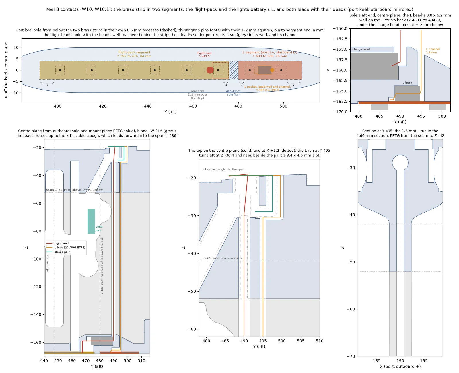
Section titled “Keel B contacts”Ryan split the charge strip on 2026-10-11 (W10, through th-eda and th-hangar). The dock charges the lights
battery through its own contact. Each keel sole has two nickel-plated brass strips, 0.5 mm thick. Each strip
is bonded flush in its own 0.5 mm recess. The sole between the strips is at the ground line, flush with the
strips. The port keel carries L+ and the starboard keel carries L-. tools/make_keel_b.py writes the
strips as placed: parts/Keel B Plate Flight (reference).stl and parts/Keel B Plate Lights (reference).stl.
parts/Keel B Plate (reference).stl holds the two strips in one file, for the tools that read the strip’s
length.
| Item | Value (measured from the parts) |
|---|---|
| Flight-pack segment | 8 x 84 mm, Y 392 to 476. Six pins at Y 401, 415, 429, 443, 457 and 471 |
| L segment | 8 x 28 mm, Y 480 to 508. Two pins at Y 485 and 499 |
| Gap | 4 mm, Y 476 to 480. 3.6 mm of sole between the two recesses (0.2 mm clearance round each strip) |
| Pin to segment end, pins at ±2 mm | Flight-pack: 7.0 mm at the forward end, 3.0 mm at the aft end. L: 3.0 mm at the forward end, 7.0 mm at the aft end |
| Charge lead hole | 3.0 mm at Y 467.5, into the forward end of the bead’s well. th-hangar asked for Y 464. The rear core’s bore is at Y 458.9 to 465.1 and stops 1.2 mm above the strip, so the hole moves aft. The hole edge is 0.9 mm from the core bore and 0.0 mm from pin 471 at -2 mm |
| Bead well | 7 x 7 mm, Y 468.6 to 475.6, under the flight-pack strip |
| L lead solder pocket | 3.0 mm wide and 1.0 mm deep, Y 487.2 to 488.8, at the forward end of the L bead’s well. Pin 485 at +2 mm ends 0.2 mm ahead of it |
| L bead | One Fair-Rite 2643001301, type 43 (th-telemetry): 3.55 mm OD (±0.15), 1.65 mm ID or more, 5.95 mm long (±0.25). It lies along Y in the sole, axis at Z -165.6, Y 488.7 to 494.7 |
| L bead well | 3.8 x 3.8 x 6.2 mm, Y 488.6 to 494.8. The floor is the back of the L strip, so the well opens into the strip’s recess. Clearance on the bead at its largest: 0.10 mm on the diameter, 0.00 mm on the length |
| What opens onto the L strip | Pocket, well and channel, Y 487.2 to 495.8: 0.2 mm aft of pin 485 and 1.2 mm ahead of pin 499, both at ±2 mm. No pin is under an opening |
| L bead well walls | PETG: 1.46 mm outboard and inboard, 1.38 mm above it to the charge bead’s tunnel (0.9 asked) |
| L lead channel | One straight 1.6 mm bore at Y 495 from the strip to Z -30.4, across the Z -52 seam on one axis. It turns aft to Y 499.6 and goes up into the kit’s cable trough beside the strobe pair. The strobe pair’s 3.4 mm channel and the L channel make one 3.4 x 4.6 mm slot at the pad. Since W11 the aft strobe tab’s 3.4 mm pair channel joins the slot from aft at Z -29.2 |
| L lead channel walls | LW-PLA blade: 1.54 mm or more (0.9 asked). PETG from the seam to Z -42: 1.53 mm (1.5 asked). The section is 4.66 mm thick there. Sole and boss: 1.66 mm. Strobe boss: 1.83 mm |
| L lead channel distances | 39.7 mm from the coil axis at the pocket (35 asked). 20.2 mm from the LoRa jack’s axis and 17.7 mm from its body (20 asked). Nothing forward of Y 494.2 above the coil (Y 480 asked). 2.7 mm from the charge lead’s channel |
| L bead distances | 41.2 mm from the coil axis (35 asked). 83.2 mm from the LoRa jack’s axis |
| L lead length, joint to the spar | About 173 mm (estimate, along the channel axes, without the bends) |
The L lead is 22 AWG, one conductor in each keel: M22759/16-22 ETFE wire, about 1.3 mm (th-eda, estimate), in a 1.6 mm channel (W10.1, 2026-10-11). The lead is soldered to the strip in the pocket. It goes aft through the bead and turns up into the channel. The bead’s aft end is 0.3 mm forward of the channel’s axis. The channel continues 1.0 mm aft of the well for the turn. Put the bead in through its well, then bond the L strip. The charge lead’s own channel at Y 490 has 1.15 mm walls in the same band, from the seam to Z -42.
Cut the two strips for each keel from one 8 x 116 mm strip: 84 mm and 28 mm. This leaves 4 mm for the cut and the deburr.
The split adds 0.5 g to each keel (sliced, before and after): blade +0.24 g, mount part +0.18 g, sole +0.09 g. The W10.1 bead well and the 1.6 mm channel change each keel by less than 0.1 g (sliced, before and after): blade -0.04 g, mount part 0.00 g, sole +0.03 g. The bead weighs about 0.3 g (estimate). The two strips weigh about 3.8 g for each keel, 0.14 g less than the one strip (estimate, brass at 8.5 g/cm³).
Source: docs/keel.md in the repo. Edit it there; this page is generated.
Comments
Comment on the whole page here, or on one section or step with the button beside it.