
Shrinking the L5 helix with a dielectric former
A study run on 2026-09-27 for the custom GNSS antenna. The question was simple: if the helix is wound on a printed former of high permittivity, how much shorter does the L5 quadrifilar helix (QHA) get, and does it fit under the 50 mm height cap? The short answer is that it fits, but the former takes most of the bandwidth and a good part of the efficiency with it. Every number below is marked as simulated, assumed or measured. Nothing on this page is measured yet.
The problem: 74 mm of helix, 50 mm of room
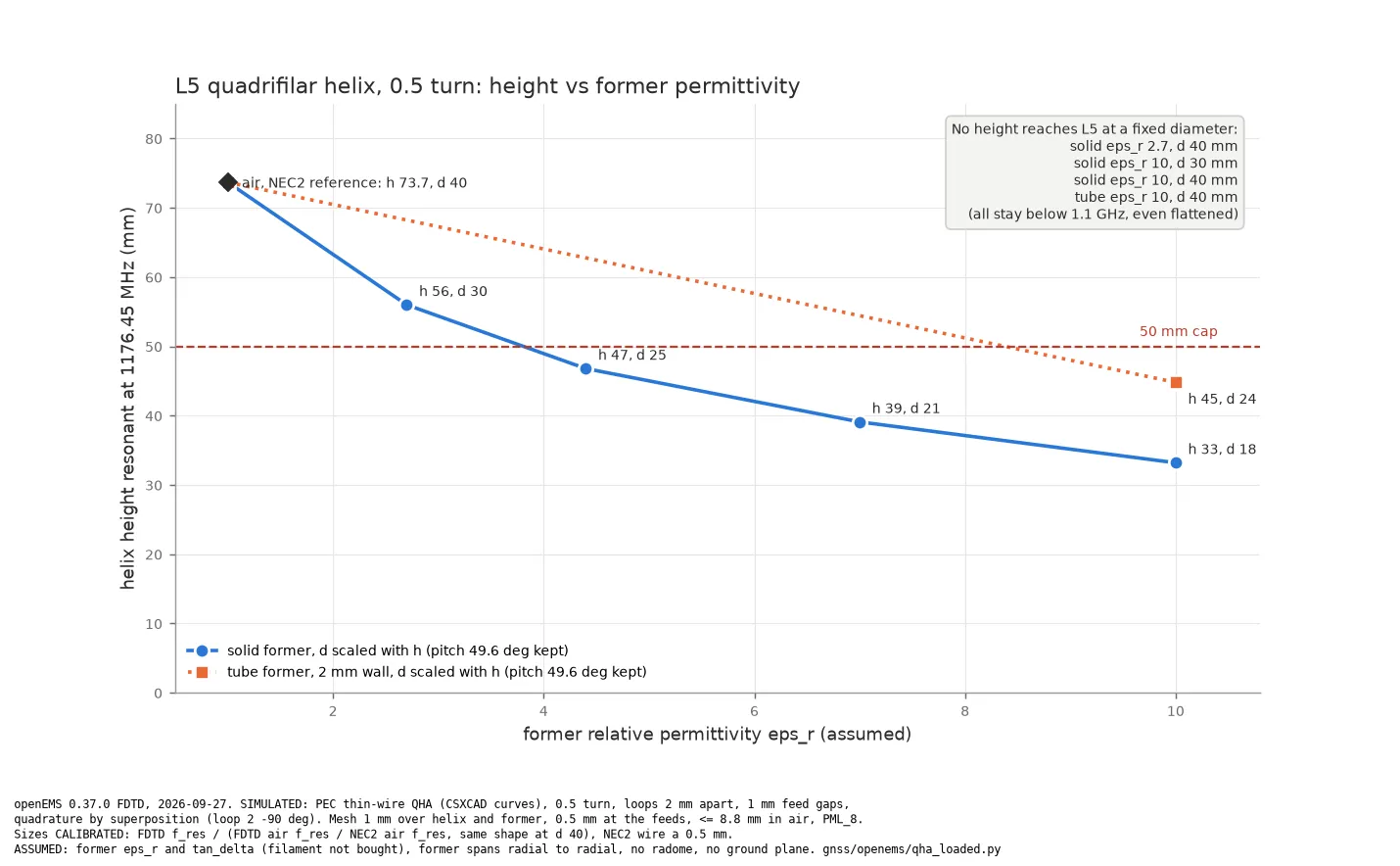
Section titled “The problem: 74 mm of helix, 50 mm of room”The NEC2 wire model (tools/qha_nec.py) gives a half-turn QHA on a 40 mm diameter that resonates
at the L5 centre, 1176.45 MHz, when the helix is 73.7 mm tall (simulated). The hatch envelope
allows 50 mm of helix. In air, no half-turn helix of a useful diameter reaches L5 inside that
height, so something has to slow the wave down.
The trick: slow the wave with the former
Section titled “The trick: slow the wave with the former”A wire lying on a dielectric sees an effective permittivity somewhere between air and the former. The wave on it is slower, so the loop reaches one wavelength at a shorter physical length. Printable high-permittivity filaments exist: Nanoe Zetamix Epsilon is sold as εr 10, tanδ 0.001, and Avient PREPERM ABS1000 as εr 10, tanδ 0.003. Both figures come from the datasheets and are specified at 9.4 GHz, not at 1.2 GHz, and we have not measured either. The study uses εr 2.7 (plain PLA or PETG), 4.4, 7 and 10, all with tanδ 0.003 unless marked (assumed).
How we tested it
Section titled “How we tested it”The FDTD model (gnss/openems/qha_loaded.py, openEMS 0.37) builds the same geometry as the NEC2
model: two bifilar loops, 2 mm apart at the radials, loop 2 turned 90 degrees, a lumped port in
the centre of each bottom radial, and a cylindrical former whose surface carries the helix. The
loops are driven in quadrature by superposition: each port is excited alone, and the two runs
are summed with weights 1 and -j. That gives the full 2 x 2 impedance matrix, each loop’s active
impedance and the combined RHCP and LHCP pattern from one pair of runs.
The air case went first, and it did not agree. The openEMS helix resonated at 1025 MHz where NEC2 says 1176 MHz, 13% low (simulated). The dipole smoke test had already taught us one mesh lesson: refine the cells at open wire tips, or resonance lands 5% low. This one was different. A thin wire that runs diagonally across a Cartesian mesh becomes a staircase, and the staircase is electrically longer than the line it stands for. Tilted-dipole tests put numbers on it: a dipole at 45 degrees resonated 6.5% low, one along the cube diagonal 12% low. Halving the cell to 0.5 mm moved the helix only from 13% to 10% low, and volumetric wires made it worse.
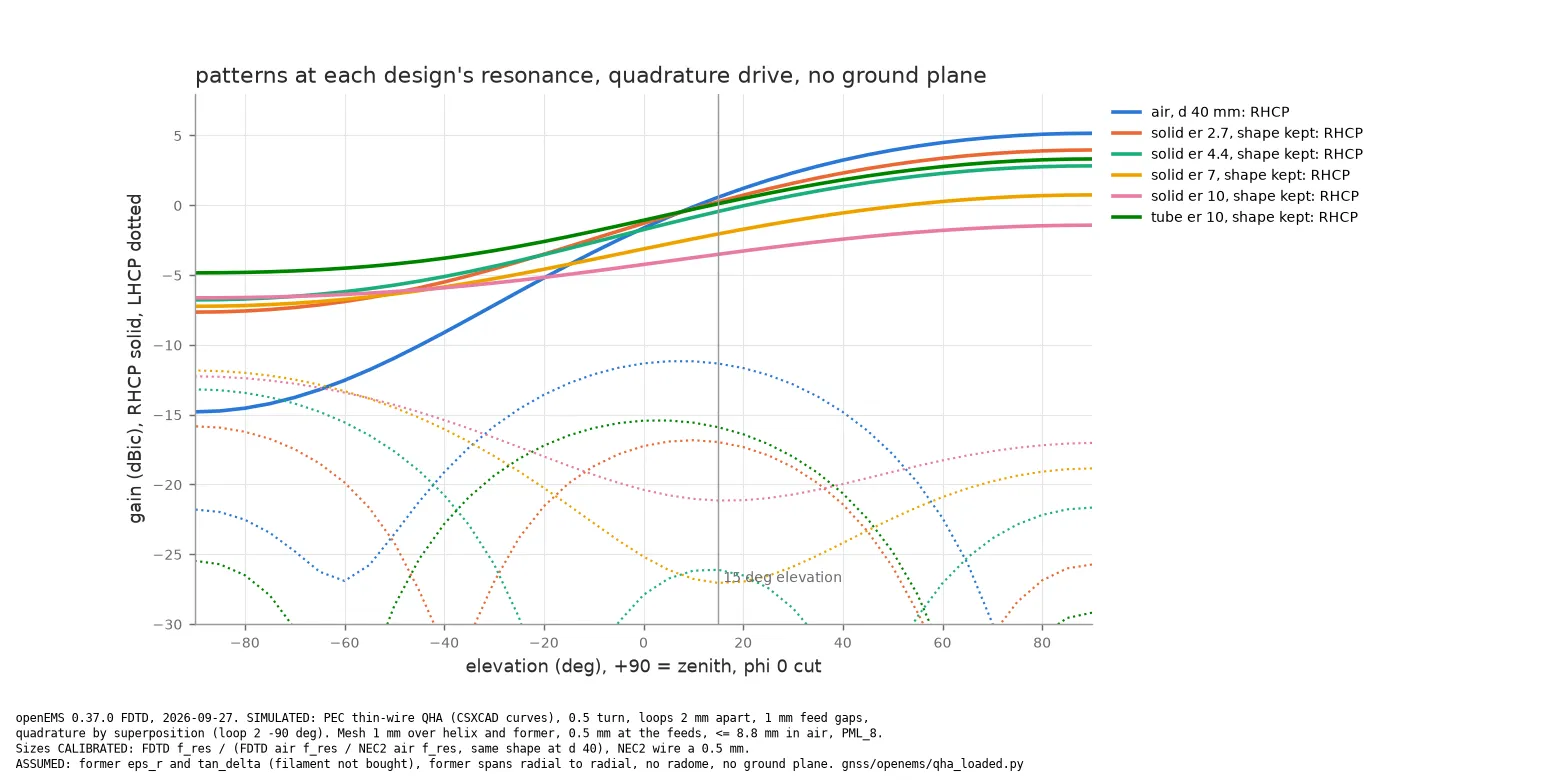
So every loaded run is calibrated against its air twin: the FDTD resonance is divided by the ratio of FDTD to NEC2 resonance for the air helix of the same shape. That ratio sat between 0.862 and 0.872 across pitch 22 to 50 degrees, so it depends little on geometry. With it the air pattern agrees with NEC2: +5.2 dBic RHCP at the zenith against +5.1, axial ratio 0.1 dB against 0.4, and -0.3 dBic against -0.6 at 15 degrees elevation (simulated). Loop resistance comes out about 20% low and bandwidth about a third narrow in FDTD, so the FDTD bandwidths below are on the pessimistic side.
Surprise: the 40 mm helix cannot reach L5 with any former
Section titled “Surprise: the 40 mm helix cannot reach L5 with any former”The plan was to keep the 40 mm diameter and shorten the helix. It does not work. A solid former of εr 2.7 already pulls the 40 mm helix below 1.07 GHz, and a squashed helix cannot climb back, because the half-turn arc and the radials alone are most of a wavelength. εr 10 solid on 40 mm resonates near 0.7 GHz, and even the 2 mm εr 10 tube stays below 0.93 GHz (all simulated). With εr 10 there is a stronger resonance near 1.2 GHz, but it is the two-wavelength loop mode, with a pattern and resistance no GNSS antenna wants.
The former shrinks the whole antenna, not only its height. So the sweep keeps the air design’s shape (pitch 49.6 degrees, half a turn) and scales the diameter and height together until the calibrated resonance lands on 1176.45 MHz.
What the numbers say
Section titled “What the numbers say”All values simulated in openEMS at each design’s own resonance, calibrated to NEC2 as above. εr and tanδ are assumed. Gain is IEEE gain (mismatch excluded) with no ground plane and no radome. The air row’s height is the NEC2 value; its other columns are openEMS. “Bandwidth” is where one loop alone stays below -10 dB against its own resistance; the L5 band needs 1.8%.
| Former | d (mm) | Height (mm) | Arm (mm) | Loop R (Ω) | Bandwidth | RHCP zenith (dBic) | AR zenith (dB) | Worst RHCP at 15° (dBic) | Front to back (dB) | Efficiency |
|---|---|---|---|---|---|---|---|---|---|---|
| Air (reference) | 40 | 73.7 | 96.8 | 28 | 2.05% | +5.2 | 0.1 | -0.3 | 20 | 99% |
| Solid, εr 2.7 | 30.4 | 56.0 | 73.6 | 8.2 | 0.69% | +4.0 | 0.6 | -2.1 | 12 | 80% |
| Solid, εr 4.4 | 25.4 | 46.8 | 61.5 | 3.9 | 0.39% | +2.8 | 1.0 | -3.5 | 10 | 65% |
| Solid, εr 7 | 21.2 | 39.1 | 51.4 | 2.3 | 0.20% | +0.7 | 1.8 | -5.9 | 8 | 44% |
| Solid, εr 10 | 18.0 | 33.2 | 43.6 | 1.5 | 0.10% | -1.4 | 2.9 | -9.0 | 5 | 31% |
| Tube 2 mm, εr 10 | 24.3 | 44.8 | 58.9 | 4.1 | 0.49% | +3.3 | 0.4 | -3.5 | 8 | 74% |
Everything from εr 4.4 up fits under the cap. The 2 mm tube of εr 10 is the best of them: it lands at 45 mm with three quarters of the power radiated and a clean pattern, because most of the field sits in air and only a thin shell of lossy material is in the way. A solid cylinder of the same filament goes 12 mm shorter and loses more than half its remaining efficiency doing it.
What it costs
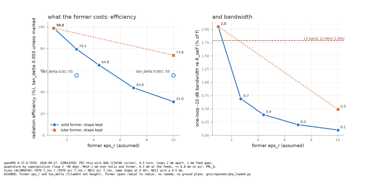
Section titled “What it costs”Shrinking an antenna in wavelengths lowers its radiation resistance and raises its Q, and the former does exactly that. Loop resistance falls from 28 Ω in air to 1.5 Ω on solid εr 10, and the bandwidth falls with it, from 2.05% to 0.1% (simulated). Even allowing for the FDTD model reading about a third narrow, no loaded design covers the 21 MHz of L5 at -10 dB. The loaded helix needs either a tuning trim per unit or acceptance of a worse match at the band edges.
Loss is the other bill. At high Q the current circulates many times before it radiates, so a small tanδ costs a lot. Solid εr 10 radiates 31% at tanδ 0.003, 55% at tanδ 0.001 (simulated, tanδ assumed). Plain PLA at a more realistic tanδ of 0.01 drops the εr 2.7 design from 80% to 55%.
There is a third cost we did not expect. The two loops couple through a mutual reactance of 12 to 23 Ω, and in air that is small next to a 28 Ω loop. On a loaded helix the loop resistance is a few ohms, so under quadrature drive the coupling moves almost all of the resistance into loop 2: loop 1’s active resistance goes to zero or slightly negative. Fed from an ideal hybrid with each output matched to the loop resistance, every loaded design reflects more than a third of its power at the band edges (simulated). The coupling must be designed out (loop spacing, radial crossing, self-phased loops) before any of these can be fed well.
Still assumed
Section titled “Still assumed”- The filament’s εr and tanδ. Datasheet values at 9.4 GHz, not measured by us, and tanδ drives the efficiency column almost alone.
- The former spans radial to radial, and the radials of one loop sit 2 mm inside it. The radial crossing is a likely source of the loop coupling, so this detail matters.
- No radome, no ground plane, no balun or hybrid losses, and ideal quadrature.
- The calibration: the air bias is assumed to carry over to the loaded helix, and it only partly does. On a 0.5 mm mesh the air helix moves up 3.4% while the εr 10 tube moves down 1%, so the calibrated tube resonates 4% lower than on the 1 mm mesh (simulated). The finer mesh resolves the 2 mm wall better and loads the helix more. Read the heights as about 4% pessimistic: the tube design is nearer 43 mm than 45. The figures use the 1 mm results.
- Size resolution: on a 1 mm mesh an 18 mm helix moves about 1% in frequency when its diameter changes by 0.2 mm, so small-diameter results carry about 1% uncertainty.
What next
Section titled “What next”Print a coupon of the filament and measure its permittivity and loss at 1.2 GHz with the VNA (a ring resonator or a filled coaxial line), because the efficiency answer depends on tanδ more than on anything we can simulate. Then wind the εr 10 tube design, measure one loop’s resonance and resistance, and compare with this page before anyone designs a feed for it.
Verdict: an εr 10 tube gets L5 under 50 mm on paper, but it loses a quarter of its power and its bandwidth is well under half of what the band needs, so the next step is measuring the filament, not printing the antenna.
Source: docs/loaded-helix.md in the repo. Edit it there; this page is generated.
Comments
Comment on the whole page here, or on one section or step with the button beside it.