
Landing and Takeoff Sensing
Status (Ryan, 2026-10-05): the downward TFmini-S is not in the base build. RTK GPS and the
barometer give the height. It returned the same day as an optional payload: “Payload Cover
(TFmini-S)” (th-blender 0900ef8) carries it on the centreline at Y 375, lens down, in place of the
blank or Survey3W cover. With that cover fitted, load params/payload-tfmini.parm after the airframe
file (serial on the LUX’s TELEM1 pads, SERIAL1; RNGFND1_POS -0.105, 0, 0.0117 m); without it, the board file’s
RNGFND1_TYPE 0 stands. On Fuselage C’s first flights the ESC payload hatch closes the bay (Ryan, 2026-10-11),
and the TFmini-S does not fly (Ryan, 2026-10-11: the 22 g it costs all-up is kept for the hatch’s mass and
a possible ESC heat plate under the 3.01 kg gate), so the file is not loaded. The Fuselage Front has no belly window and the belly mount is out of the build (th-blender
eafec85). The first build has no RNGFND rows. The rest of this page is the design for when the
sensor returns: the mount, the window and the offsets below describe the withdrawn baseline, and the
figures are a record of it. What the first build does without the sensor is in “Height without the
rangefinder” below.
What the aircraft can sense in the vertical phases, what ArduPilot does with each sensor, and the work list to fit it. Written 2026-09-27 against ArduPilot master 4c98c92, which is what Plane 4.7.1 was cut from; every claim about behaviour below was read in that source, not in a forum. Prices are point-in-time with a link. The scope is takeoff, hover and landing. Cruise is out of scope: at 20 m/s a 13 m sensor gives 0.6 s of warning and the turn radius is tens of metres.
What ArduPilot does with each sensor
Section titled “What ArduPilot does with each sensor”| Sensor | Plane 4.7 behaviour | Where in the source |
|---|---|---|
| Downward rangefinder | Used for VTOL landing and takeoff when bit 1 of RNGFND_LANDING is set: the final descent below Q_LAND_FINAL_ALT (ArduPilot’s default is 6 m; the kit’s setup guide sets 3 m and our SITL uses 3 m), touchdown detection, throttle suppression near the ground, and the height hold in QLOITER. Bit 2 adds VTOL assist, bit 3 the initial climb in QRTL and AUTO |
ArduPlane/Parameters.cpp (RNGFND_LANDING), quadplane.cpp, mode_qland.cpp, mode_qloiter.cpp |
| Forward rangefinder | Nothing automatic. Plane reads it and logs it; only a Lua script can act on it | AP_RangeFinder, AP_Scripting bindings |
| Scanning lidar (proximity) | Not supported. ArduPlane does not build the proximity library, and its only avoidance type is ADS-B. The stop-and-slide avoidance of Copter does not exist in the Q modes | ArduPlane/Plane.h has no AP_Proximity; AP_Proximity_config.h |
| Precision landing target | Supported through the Lua applet plane_precland.lua: QLAND, QRTL, AUTO VTOL landings and, on a switch, QLOITER. It needs a downward rangefinder for PLND_ALT_CUTOFF |
libraries/AP_Scripting/applets/plane_precland.lua |
So the downward rangefinder is the sensor that changes how the aircraft lands. The others are either data for scripts we have not written, or unsupported.
Decisions
Section titled “Decisions”1. Downward rangefinder: Benewake TFmini-S
Section titled “1. Downward rangefinder: Benewake TFmini-S”The rating that matters is range at 10 % reflectivity in sunlight, not the headline range, because
the pad is stainless and the ground around the hangar is whatever it is. RNGFND1_MAX is set to
that figure.
| Sensor | Range at 90 % | Range at 10 %, in sun | Mass | Interfaces | Sealed | Price |
|---|---|---|---|---|---|---|
| Benewake TF-Luna | 8 m | about 2.5 m | 5 g | UART, I2C | no | about $30 |
| Benewake TFmini-S | 12 m | 7 m at 70 klux | 5 g | UART, I2C | no | $44.99 |
| Benewake TF02-Pro | 40 m | 13.5 m at 100 klux | 50 g | UART, I2C | IP65 | $87.90 to $99.99 |
| LightWare SF20/C | 100 m | 100 m class | 10 g | UART, I2C | no | $279 |
The TFmini-S is the choice, and the reason is the airframe, not the sensor. th-main’s fit
(tools/space_map.py --rangefinder) places each sensor lens-down with its beam column extended to
the belly skin and every bracket, route and channel exit as an obstacle. The TF02-Pro’s 69 × 41.5 mm
face with 26 mm of depth fits nowhere in the baseline build (Survey3 and P50B): under the pack there
are 5 to 7 mm to the belly, the pockets beside the P50B are about 30 mm wide, and the one place it
fits in the stock build is the Survey3’s own spot. The TFmini-S fits every build at (-48, 225) in the
starboard pocket, aft of the channel exit keep-out, 10 cm from the sense board, with all wiring routes
still clear. Its 7 m in sun covers the whole final descent from 3 m with margin and the QLOITER
height hold; above 7 m ArduPilot falls back to the barometer, which is normal rangefinder behaviour.
The TF02-Pro stays the pick only for a Tattu build, where it fits at (45, 167) beside the pack. IP65 matters on a belly-mounted
sensor that lands on a wet pad. The SF20/C buys range the landing does not use for three times
the money. Sources: Benewake TF02-Pro datasheet,
TFmini-S datasheet,
DFRobot TF02-Pro $87.90, Lumenier $99.99,
LightWare SF20/C $279, ArduPilot Benewake page.
Where. Starboard pocket of the battery bay, centre (-47.5, 225, -4), lens down, long axis fore and
aft, plug facing outboard. The mount is parts/TFmini-S Belly Mount.stl from
tools/make_rangefinder_mount.py, 5.5 g of PETG: a plate glued to the floor and tray, the lens face
on a shoulder, the two lens bosses in an obround bore flared 2 degrees to match the sensor’s field of
view, two towers that take the ears with M2 screws, and two 2 × 2 mm drain slots at the ends of the
bore through the belly so nothing pools against the lens. The lens tips sit about 10 mm inside the
skin. The bore is not narrowed below the lens apertures, which would clip the receiver. The belly
window is in parts/Fuselage Front (rangefinder window).stl: 13.1 × 24.0 mm at the skin, 1.9 cm³
removed from the kit part. That is a kit-part change of the same kind as the Survey3 cutout; Ryan
approved it on 2026-09-27 and it is the part the slicer prints in every build. The TFmini-S is not sealed; the recess and drains are the
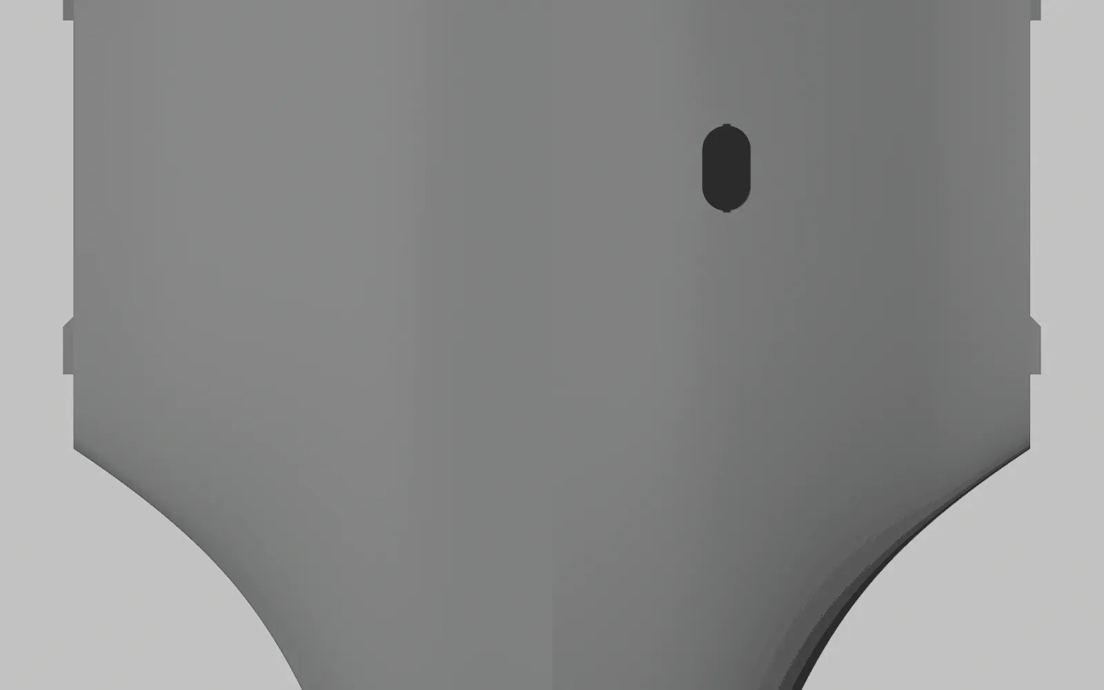
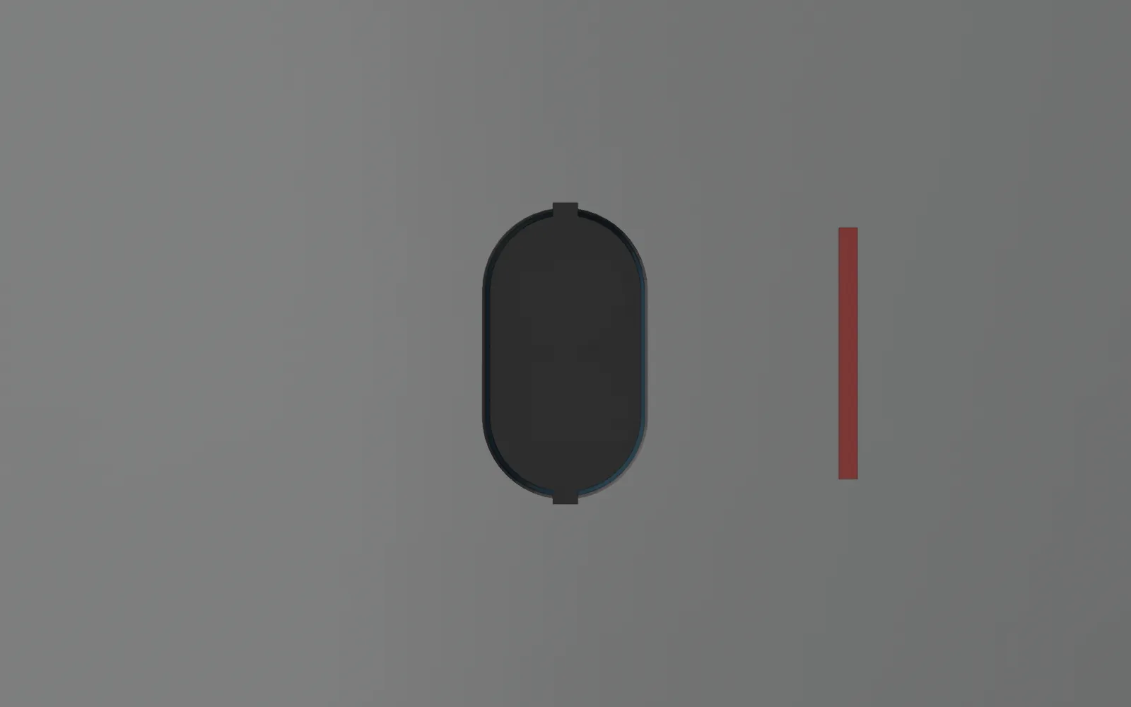
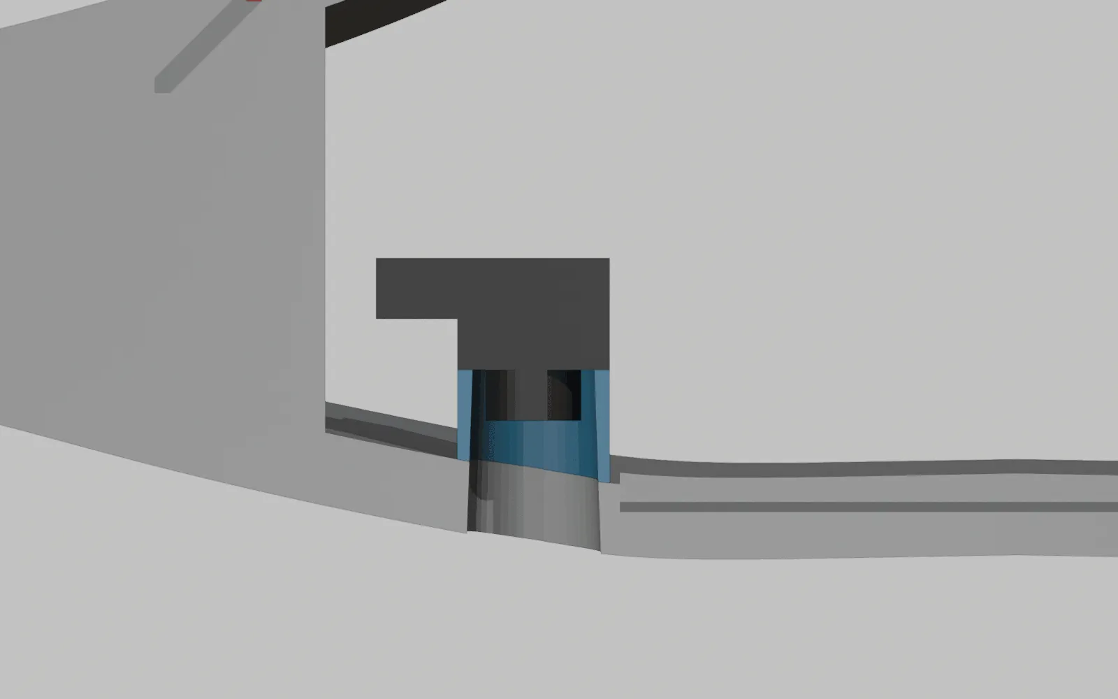
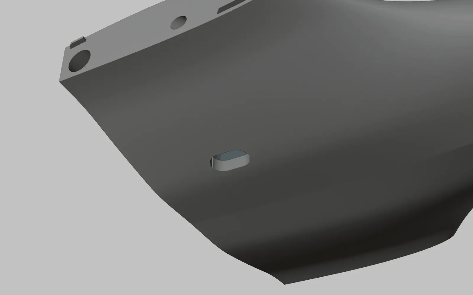
mitigation, and the aircraft lands under the hangar roof or on dry ground. parts/TFmini-S (reference).stl is the sensor envelope for fit checks. Renders from tools/render_rangefinder_window.py: images/rangefinder-window-belly-wide.png
(the belly from below, nose at the bottom: starboard is on the right because the view is from underneath),
images/rangefinder-window-belly-zoom.png (the window with a 20 mm bar; the two notches are the
drain slots), images/rangefinder-window-section-zoom.png (a section at Y 225 looking aft: the
mount in blue on the floor, the sensor on it, the flared bore through the skin) and
images/rangefinder-window-three-quarter.png. The power bracket’s zip-tie anchor moved
4 mm outboard to clear the mount.
Mass and CG. 5 g at Y 225: no measurable CG change. The TF02-Pro would have been 50 g, 46 mm forward of the CG, about 1 mm of shift.
2. Bus: DroneCAN, on its own node in the end
Section titled “2. Bus: DroneCAN, on its own node in the end”Ryan wants the sensors on CAN. The Lucid has one CAN port, which fixes the options.
| Option | What it takes | Verdict |
|---|---|---|
| UART straight to the Lucid | One of the three free UARTs, SERIALn_PROTOCOL 9, RNGFND1_TYPE 27 |
Simplest. The fallback if the node path has any trouble |
| Benewake’s native CAN sensors (TF02-i, TF03-CAN) | CAN_D1_PROTOCOL 11, their own protocol on the bus |
Excluded. They are not DroneCAN and cannot share the one bus with the airspeed sensor and the node |
| DroneCAN via the charge node sense board | Enable AP_PERIPH_RANGEFINDER_ENABLED in the hwdef, sensor on the board’s I2C header, FC RNGFND1_TYPE 24 |
Interim. The board is 10 cm from the sensor and the firmware is one define; this is how the sensor is wired until the node below exists |
| DroneCAN via a third board of ours | STM32, CAN transceiver, sensor header, AP_Periph, like the charge node’s sense board without the pack sensing | Ryan’s decision, 2026-09-27. A rangefinder node with its own failure domain and firmware. Filed, not started |
| DroneCAN via a Matek CAN-G474 adapter node | $21.16, 5.2 g, 4 UARTs, 2 I2C, anywhere on the bus | The answer for any sensor far from the sense board, such as a nose sensor |
Sources: ArduPilot DroneCAN setup
(RNGFND1_TYPE 24; the sensor id is the node’s RNGFND1_ADDR, which for an I2C sensor is its bus address), Matek CAN-G474 at RMRC.
Lead. The sensor’s own four-wire cable, cut to length and soldered to the sense board: SDA and
SCL to the J11 pads, 5 V and ground to the J8 pads. Route from tools/wire_routes.py: P50B path
67 mm, cut 177 mm with the hatch service loop; Tattu path 149 mm around behind the pack, cut
191 mm.
The rangefinder node. Working name TerraHawkRangeNode, reserved DroneCAN node id 22 (the FC is
10, the charge node takes 20, the airspeed sensor 21, the lift ESC nodes 24 to 27, the elevon servo nodes 28 and 29; set them static in each node’s CAN_NODE
rather than leaving allocation dynamic, so the FC’s RNGFND1_ADDR and the log always name the same
device). It sits in the starboard pocket beside the sensor with two CAN connectors for pass-through, so
bus 2 becomes airspeed, rangefinder node, charge node, servo nodes and the FC stub, terminated at
the airspeed sensor and a terminator plug in the harness’s last connector. When
it exists, th-eda removes the J8 and J11 lead from the harness table and the rangefinder define
leaves the charge node firmware. The FC configuration does not change.
Interim node firmware change, in hw/charge-node/hwdef/TerraHawkChargeNode/, not yet made:
| Line | Why |
|---|---|
define AP_PERIPH_RANGEFINDER_ENABLED 1 |
Build the rangefinder library into the node |
RNGFND1_TYPE 25, RNGFND1_ADDR 16, RNGFND1_ORIENT 0 in defaults.parm |
Benewake I2C driver at address 0x10; the node publishes with sensor id 16, the FC sets the real orientation |
RNGFND1_MIN 0.1, RNGFND1_MAX 7 on the node |
The node uses these to flag out-of-range in the CAN message; 7 m is the sunlight figure |
The board’s I2C header J11 is four 1.27 mm pads (3V3, SCL, SDA, GND) and carries no 5 V. The TFmini-S needs 5 V with 3.3 V I2C logic, so its lead takes SDA and SCL from J11 and its 5 V and ground from the LED-strip pads J8 (pin 1 is the node’s 5 V rail, pin 3 ground). That rail is the CAN bus 5 V through the node’s load switch, so the sensor’s draw, 140 mA average and 200 mA peak, lands on the Lucid’s 5 V BEC alongside the node’s 60 mA, the airspeed node, the GPS, the receiver and the telemetry radio: under 1 A in total against the BEC’s 3 A. No board change. The sense board firmware stays at about 170 KB of 1 MB.
FC parameters: RNGFND1_TYPE 24, RNGFND1_ADDR 16 (a node publishes each rangefinder with its I2C address as the sensor id, see AP_Periph/rangefinder.cpp), RNGFND1_ORIENT 25 (down),
RNGFND1_MIN 0.1, RNGFND1_MAX 7, RNGFND1_POS_X 0.046, RNGFND1_POS_Y -0.048, RNGFND1_POS_Z from the fitted height,
RNGFND_LANDING 2 (takeoff and landing only, to start), Q_LAND_FINAL_ALT 3 as the setup guide has it.
The pre-arm clearance check and the landing hold, with an upward rangefinder and a people radar on the same node, are on clear-to-launch.md.
3. Forward rangefinder: not yet
Section titled “3. Forward rangefinder: not yet”Plane does nothing with a forward rangefinder on its own. It could feed a Lua script that holds the aircraft in QLOITER when something is closer than a limit, or refuses a VTOL takeoff with an obstacle ahead, but that script does not exist and the behaviour has to be designed before the sensor is worth buying. If it is fitted later, the nose is the place, a TFmini-S (5 g) is enough at hover speeds, and it goes on the bus through a Matek CAN-G474 in the nose or on a Lucid UART. Ryan asked for this item by name, so it stays on the list as research, not purchase.
4. Scanning lidar: no
Section titled “4. Scanning lidar: no”The SF45/B (58 g, 50 m, $449) has nothing to drive: Plane has no proximity avoidance. A proximity ring near the hangar would need a companion computer commanding GUIDED, which is a project of its own. Reviews also report failure above 75 klux. Revisit only with that project. Source: LightWare SF45/B, iRLock listing $449.
5. Precision landing: RTK now, a printed marker later
Section titled “5. Precision landing: RTK now, a printed marker later”The hangar plan lands on RTK (a few centimetres). Its fallback was an IR beacon until the price
was checked: IR-LOCK’s MarkOne V3.0 lists at $2,949 and its sensor at $349
(irlock.com). hangar.md now puts an AprilTag
constellation on the deck and strip instead. The partner to the downward rangefinder is the applet’s
MAVLink path: a small computer with a camera on the aircraft reads the tags (OpenCV’s ArUco module
reads the AprilTag families) and sends LANDING_TARGET at 1 Hz or more, with PLND_TYPE 1. That is about $60 to $100 of hardware and a software project. Order of work:
RTK landing first, the downward rangefinder now (the applet needs it), the marker system as the
upgrade if RTK alone does not hold ±125 mm. Sources: Plane precision landing,
applet source.
6. SITL first
Section titled “6. SITL first”Before any purchase, the simulator shows what the rangefinder changes. Parameters for
sim/terrahawk.parm, for the simulator session:
| Parameter | Value | Why |
|---|---|---|
RNGFND1_TYPE |
100 | SITL rangefinder |
RNGFND1_ORIENT |
25 | Down |
RNGFND1_MIN |
0.1 | TFmini-S minimum |
RNGFND1_MAX |
7 | TFmini-S at 10 % reflectivity in sun |
RNGFND1_POS_X |
0.046 | 46 mm forward of the CG, in metres; X is forward in the body frame |
RNGFND1_POS_Y |
0.048 | 48 mm to starboard (assembly X -48; +X is port in the STL frame, 2026-10-04) |
RNGFND_LANDING |
2 | Takeoff and landing only |
Q_LAND_FINAL_ALT |
3 | The setup guide’s value, already in the parm |
Then fly a QLAND and a QRTL and compare the descent profile and touchdown against the same
mission with RNGFND_LANDING 0.
Flown 2026-09-27 (th-simulator, commit e30fc86; write-up in sim/README.md under “Landing with
the rangefinder”, screenshots in artifacts/screenshots/2026-09-27/rng-*.png). The approach is
identical to the metre with and without the sensor. With it, ArduPilot reports the rangefinder
engaged at 13.2 m on the QRTL approach, the slow-down to the 0.3 m/s final starts about 2 m higher
(10 to 6 m at 1.10 m/s against 1.33; 6 to 3 m at 0.39 against 0.60), “Land final started” comes at
about 4 m instead of 2.5 m, and touchdown is 4 s later at the same 0.29 to 0.30 m/s. QLAND from
30 m shows the same pattern. The landing detector is unaffected: “Land complete” 6 s after touchdown
in every case. What SITL cannot show is the reason to fit the sensor at all: its barometer does not
drift, so on the real aircraft the sensor’s true height is the difference and it is invisible here.
The run used 13.5 m for RNGFND1_MAX. Re-flown with the TFmini-S’s 7 m (27b19d9), the sensor
engaged at 6.75 m and the descent profile was the no-sensor profile to the decimal: the earlier
2 m slow-down came from a sensor that engaged far above the final, and at 7 m there is nothing left
for it to change in SITL. Its value on the aircraft is the true-height reference against barometer
drift, which is exactly what the simulator cannot show.
Two landing findings from the same session that are not about the sensor: QRTL from 50 m on
ArduPilot’s default 65 degree bank limit flew into the ground twice (63 degrees of bank at 25 m/s is
near the trimmed stall at 2.37 kg), so terrahawk.parm now carries ROLL_LIMIT_DEG 45 and
Q_RTL_ALT 40, which also keeps the return above Q_ASSIST_ALT 25. For the marker upgrade later: SCR_ENABLE 1, the applet in
scripts/, PLND_ENABLED 1, PLND_TYPE 4 (SITL target) and SIM_PLD_ENABLE 1.
Height without the rangefinder (the first build)
Section titled “Height without the rangefinder (the first build)”Without a rangefinder, a VTOL landing takes its height above the ground from the EKF: the height
above the landing target, which is home’s height for a landing at home or at a waypoint given relative
to home (Plane::relative_ground_altitude, altitude.cpp at 4c98c92). The EKF height comes from the
barometer (EK3_SRC1_POSZ at its default), and the RTK GPS does not correct it. The landing descends
at the VTOL descent speed until 3 m by that height (Q_LAND_FINAL_ALT 3), then at 0.3 m/s
(Q_LAND_FINAL_SPD), and the land detector (throttle at its lower limit with no climb) ends it.
Two errors move the start of the slow final descent: barometer drift and ground effect (the EKF
reads higher than the truth), and ground that is not at home’s height (a landing away from home, such
as a battery QLAND over the survey area, assumes the ground is at home’s height). Both act the same
way. th-simulator measured it (c9b9547, sim/landing_height.py; the barometer ramped high, then QLAND):
| EKF reads high by | Slow descent starts at (true height) | Touchdown | Touchdown to disarm |
|---|---|---|---|
| 0 m | 3.7 m | 0.31 m/s | 6.5 s |
| 1 m | 2.6 m | 0.31 m/s | 6.6 s |
| 2 m | 1.6 m | 0.30 m/s | 5.9 s |
| 3 m | 0.6 m | 0.34 m/s | 6.1 s |
| 4 m | not reached | 0.58 to 0.59 m/s | 12.4 s |
So Q_LAND_FINAL_ALT 3 already covers about 3 m of error: the position controller slows the 1.5 m/s
descent before the final height. At 4 m the aircraft touches at 0.6 m/s, and the land detector takes
twice as long. Without the rangefinder, every dock landing, threshold landing and battery landing in
the SITL test set was unchanged (an undrifted SITL barometer is within 0.08 m of the truth).
For the first flights, which are short and near home, the settings stay as they are. 1 hPa of pressure change is about 8 m of height; a fast weather change can move the pressure that much in an hour or two, but a short flight in steady weather drifts far less than 3 m (an estimate, not measured). For long surveys, two ways to correct the drift with the RTK height are open:
EK3_OGN_HGT_MASK5: the EKF corrects the barometer height toward the GPS height continuously, through a filter with a time constant of about 15 to 20 s (AP_NavEKF3_PosVelFusion.cpp). In SITL (th-simulator 3b61155) it held the EKF within 0.5 m during realistic drift, and every landing began its slow descent at 3.6 m. But it also follows a GPS height error: a reported poor accuracy slows it without stopping it, and a GPS that reports good accuracy while wrong is followed within about a minute. Every case still touched at 0.37 m/s or less, because the 3 m final height bounds both errors. Realistic cases (th-simulator d95bf90): a drop from RTK fixed to float is invisible, but a drop to a 3D fix is adopted at 0.1 to 0.4 m per 10 s, so after about 2 minutes on a 3D fix most of its height error is in the EKF (a +4 m step touched at 0.57 m/s). And if the first fix at boot is a 3D fix that reads low and RTK fixes in the air, the EKF ends up to 4 m high. Both have guards: RTK fixed for 30 s or more before arming (in SITL, 10 s was enough to remove the boot trap), and a landing that waits for 30 s of RTK fix, counted from the fix flag (in SITL the re-fix correction was complete after about 20 s, so 30 s is the minimum; th-simulator). A survey beyond the radio range loses RTK for its middle; with the mask, the height there follows the 3D fix, and the fix back near home corrects it within seconds.
Decision (th-avionics, 2026-10-05): the first flights keep EK3_OGN_HGT_MASK 0. Without the mask only a
barometer drift of more than about 3 m can land fast, and short flights near home do not drift that
far. Long surveys move to mask 5 together with its two guards in the flight script (the RTK-fix pre-arm,
sharing the script’s one arming slot, and the landing wait); the mask needs a reboot to change, so it
cannot be switched in flight. With the TFmini-S payload fitted, neither error matters.
- GPS height as the EKF height source near the landing (
EK3_SRC2_POSZ3). In SITL it held the EKF within 0.06 m at every offset, but it needs a rule to select it only while RTK is fixed, and the height step at the switch is not measured.
With the TFmini-S payload fitted, the rangefinder starts the slow descent at the true 3.6 m at every offset (touchdown 0.30 to 0.31 m/s), and its position 15 cm aft changed nothing in the dock landings.
Work list
Section titled “Work list”- th-simulator: SITL rows in, QLAND and QRTL flown with and without the rangefinder (e30fc86).
- th-simulator:
RNGFND1_MAX7 in the parm and one QLAND flown with it (27b19d9). - th-main: fit. TFmini-S at (-48, 225) in every build; TF02-Pro fits only Tattu builds.
- th-main: the belly mount, the window part (13.1 × 24.0 mm) and the sensor envelope, in
parts/, fromtools/make_rangefinder_mount.py; the lead route. - Ryan: the belly window in the Fuselage Front is approved (2026-09-27).
tools/slice_all.pynow printsFuselage Front (rangefinder window)in every build; the bed is re-sliced (12 h 14 min, 83.2 g of LW-PLA). - Ryan: the TFmini-S on the parts order.
- th-avionics: the interim rangefinder define in the charge node firmware and a rebuild; the FC parameters on the tutorial’s parameter page.
- th-avionics and th-eda, later: the rangefinder node,
TerraHawkRangeNode, node id 22; hwdef first, then the board. Not started. - th-eda: the rangefinder lead in the harness table (sensor cable, cut 177 mm P50B or 191 mm Tattu, soldered to J11 and J8).
- th-hangar (2026-09-27): the IR beacon in
hangar.mdis replaced by an AprilTagtag36h11constellation, nine tags in three sizes on the deck and strip where feet never land, generated bytools/make_pad_markers.py; the beacon’s price is noted there. - Later, if wanted: the forward-rangefinder Lua behaviour, then the sensor; the marker camera system.
Source: docs/landing-sensing.md in the repo. Edit it there; this page is generated.
Comments
Comment on the whole page here, or on one section or step with the button beside it.