
Measured, not assumed
The manual gives cut lengths and says “long M3 screws”. It doesn’t give bore diameters, bolt patterns or foot positions. Everything else in this repo needed those numbers, so they were measured from the STL pack itself: slicing each part and fitting circles to the through-holes. This page explains the frame the measurements live in and why a few of them matter more than they look.
The frame the STLs share
Section titled “The frame the STLs share”The pack is exported in CAD assembly coordinates, with X to port, Y aft with the nose at Y = 0, Z up, in millimetres (a right-handed frame; until 2026-10-04 this site called +X starboard, and every side word followed that). Every part already sits in its place on the aircraft. To assemble the whole airframe, the Blender build resets each transform and mirrors the one-sided parts across X = 0. No part was positioned by eye. Spar axes, motor bolt plates and the servo bay all come from the mesh bores.
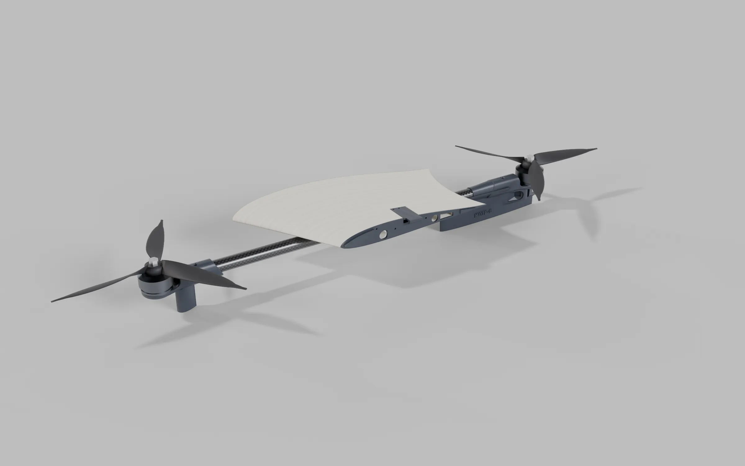
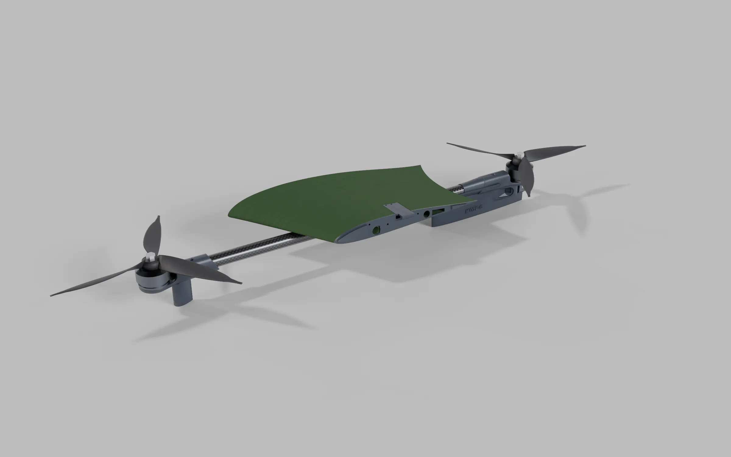
The port VTOL Section of Fuselage C v2.4B on its 14 mm spar: the lightweight-PLA Section with its PETG Section Plate at the wing joint and our Wing Clip in its pocket, the PETG Spar Mount and the TPU wire window cover, an EMAX ECO II 2807 with its Gemfan F8041 3-blade prop and M5 nut at each end of the spar, and under the Section the two PETG gear mounts of keel B, the bolt-pilot stilt mount forward and the cable-riser keel mount aft, which take the place of motor mounts (th-blender W84); the part mark K01P-B raised on the keel mount's outboard face (th-blender W129). 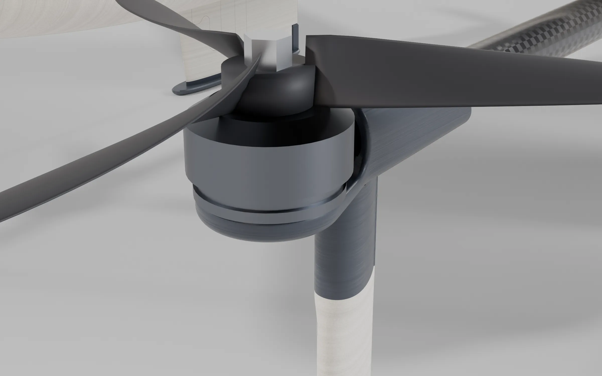
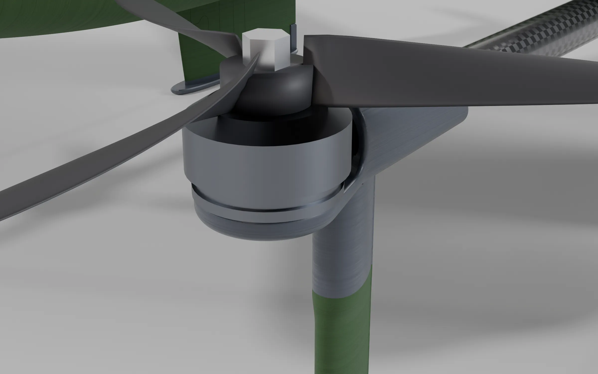
The port front lift pod of Fuselage C v2.4B from forward and above: the EMAX ECO II 2807 on the VTOL Section's PETG spar mount at the tip of the 14 mm spar, with the Gemfan F8041 3-blade prop on it, and under the pod the front stilt's PETG bolt-pilot mount with the LW-PLA stilt blade running down out of it (th-blender W83).
Clearances say what each bore is for
Section titled “Clearances say what each bore is for”| Spar | Bore | Clearance | What that means |
|---|---|---|---|
| 14 mm woven | 14.3 mm | 0.3 mm | Structural and drilled through. Buy a true 14.0 mm OD, matte finish |
| 8 mm rear fuselage | 8.3 mm | 0.3 mm | Same rule: a real 8.0 mm pultruded tube |
| 8 mm wing | 8.8 to 8.9 mm | 0.8 to 0.9 mm | Loose on purpose, to absorb foaming-filament ooze, not to take a bigger tube |
| 6 mm elevon | 6.6 to 6.9 mm | 0.6 to 0.9 mm | The spar is the hinge pin, so it swings without reaming |
The wing bores are the reason for one of the manual’s warnings. “Avoid crossing walls” has to be on, and the clearance is there for foaming-filament ooze, not for a bigger tube. Full numbers are in order and cut the spars.
A 5 mm plate and a 10 mm screw
Section titled “A 5 mm plate and a 10 mm screw”The lift-motor mount plate is 5.0 mm thick, and the XING2 2809 ships with M3 × 10 screws. That leaves 5 mm of thread inside the motor base, enough to reach the windings, which the manual warns will short the motor. This is why the hardware list says M3 × 8 in bold. It’s the one measured number that can destroy a part on the first power-up. The build now flies EMAX ECO II 2807 motors (2026-10-04), whose screws are not measured yet; check them against the base the same way.
Overall size
Section titled “Overall size”Measured in the assembly frame, the airframe is 1484 mm across the wing and about 233 mm tall on its gear, from the ground to the top of the spine radome. Its body runs 603 mm from the nose cone (Nose 15mm) to the end of Tail B, and the pusher motor stands bare for another 44.5 mm, so the aircraft is about 648 mm long to the motor’s aft face and about 658 mm from the tip of the pitot, which runs through the nose cone above the camera to Y -10. These are from the spine rear fuselage (decided 2026-09-30). On 2026-10-03 Ryan removed its aft top hatch: the top, the spine and the radome are now one 7 mm shell on Fuselage Mid B, and the radome follows the Q43’s real profile, 1.4 mm lower than the crowned top it replaced. Since 2026-10-03 the first build prints them, with the payload bay in Fuselage Mid B and Tail B. This build’s own flat wing tip, chosen on 2026-09-29, ends at the same place within a millimetre (1483 mm across). The Winglet Stabilizers, the small fins that stood highest on the first design, were deleted on 2026-09-27 (Wing aerodynamics). The folding pusher in the renders trails its blades to about Y 753, some 104 mm behind the motor; the first build flies a fixed APC 10 × 7E (2026-10-04), which turns just behind the motor.
Where the feet land
Section titled “Where the feet land”Each VTOL motor mount carries a printed foot blade with a tip roughly 4 × 11 mm. The four tips sit at X ±190 mm and Y 68 / 484 mm, a 380 × 416 mm rectangle.
The landing gear is keel B (decided 2026-09-29). A stilt 8 mm thick and 20 mm along the airflow hangs under each front motor mount, its section running straight up into the spar sleeve, on a 16 mm canoe sole from Y 53 to 83. At the rear, a keel hangs under each VTOL spar from Y 380 to 520: a streamlined blade 9 mm at its thickest, shaped round the spar so landing loads go into it, on a canoe sole up to 20 mm wide that carries the charging plate. Each blade is lightweight PLA on a PETG mount part grown from the kit’s VTOL motor mount, joined at a seam 52 mm below the datum, where the glass or carbon cores run 22 mm into blind bores in the PETG mount (2026-10-06; at 30 mm the single-wall blade failed a gentle touchdown). Printed as one PETG part, the keels would have cost about 110 g all-up once the nose ballast followed them; split, about 3 g. On this gear the aircraft stands 168 mm below the datum, as it did on keel A, so even an open 10-inch pusher blade that stops pointing down clears the ground by 41 mm. The pusher prop folds aft as well (decided 2026-09-27), so a blade that touches something on landing swings away.
Every part of the gear is a streamline section, because four bare posts would cost about 50 W in cruise. Keel A, the first keel (2026-09-27), cost about 12 W and paid for it: as a fin it gives about a third more yaw stability than any stilt arrangement tried (Wing aerodynamics). Even so, the fine-mesh CFD put the gear at 14 to 16% of cruise drag, so keel B keeps the fin and reshapes everything the air meets: a NACA four-digit section 9 mm thick, the blade running straight up into the mount with a 3 mm fillet at the root, and narrower canoe soles in place of keel A’s 30 mm square ones. Plain roots won over a flared blend into the mount on 2026-09-30: the coarse CFD gave 4.2% less whole-aircraft drag, most of it at the front stilts. Its drag against keel A is still being computed. The parts on the site are review outers; the hollow shells, the glass cores and the antenna cassette follow the strength checks (Landing gear).
The gear also sets the hangar pad. The aircraft lands on a flat pad, and the dock then slides it onto the charging contacts (decided 2026-09-28): one pair of push bars closes on the toe faces of the stilt soles and the heel faces of the keel soles, which also squares the heading, and a second pair centres it across the box. With the heading within ±10°, the centre of the gear may land within ±193 mm sideways, about 269 mm forward and 142 to 147 mm aft of the aim point. The forward limit is the pitot tip of the longer Fuselage C nose. Ryan picked nose layout v2.4B (2026-10-13): the nose 6 mm longer, with the lift ESC behind the pack. Its pitot tip, our own tube beside the camera at Y −25.54 (th-blender W104, 2026-10-19), sets the forward capture at about 274 mm, 25 mm clear of the front wall (th-hangar e9c23e70, 647072eb). The walls set those limits, not the gear: sideways the wingtips, aft the folded pusher blades, each kept 20 mm clear, and forward the parked front bar, which also acts as a backstop. The aim point sits 13 mm forward of the pad centre. An earlier pad steered the gear down printed troughs onto the contacts, which needed the aircraft within about ±12 cm; gusts took that away. See the hangar.
Stand-ins, where no mesh exists
Section titled “Stand-ins, where no mesh exists”The motors (2807-class lift, 3115 pusher) and props (8 × 4.1 bi-blade lift, folding 10 × 7 pusher drawn folded aft) in the renders are procedural stand-ins. The pusher is modelled on the Aeronaut CAM Carbon Z 10 × 7 (decided 2026-09-27); the first build flies a fixed APC 10 × 7E in its place (2026-10-04, see Propulsion). The stand-ins are sized from datasheets. Swap in vendor CAD before trusting a clearance that involves them. The Survey3 camera is an envelope too. MAPIR doesn’t publish where the lens sits on the camera face, so the belly bezel was drawn to tolerate a lens up to 19 mm off-centre along the span and 11 mm fore and aft. Measure the real camera and set LENS_OFFSET in tools/make_survey3_mount.py if it falls outside that.
Comments
Comment on the whole page here, or on one section or step with the button beside it.