
Lights
Requirements for the aircraft lights: position lights, anti-collision strobes and a landing light, on a DroneCAN lights node. Ryan asked for them on 2026-10-06, for night flight. The landing light also lights the pad for the dock (Ryan, 2026-10-06). th-avionics writes the requirements and the node firmware, th-eda designs the board, th-blender the mounts, and th-aeronautics checks mass, CG, drag and energy. Nothing here is built. All LED values are estimates from typical datasheet values until th-eda confirms the parts and their stock.
14 CFR 107.29 permits night operation with anti-collision lighting that is visible for at least 3 statute miles and has a flash rate sufficient to avoid a collision. The same rule applies in civil twilight. The remote pilot may reduce the intensity of the anti-collision lighting if that is in the interest of safety. Part 107 does not require position lights; the aircraft has them to show its orientation to the pilot and to other aircraft.
Part 107 gives no intensity in candela. As a design target, use the manned-aircraft value: an effective intensity of 400 cd in the horizontal plane, at 40 to 100 flashes a minute (14 CFR 23.1401 before the 2017 rewrite; confirmed by th-eda: 23.1401(f), the same text as 25.1401, gives 400 cd at 0 to 5 degrees above and below the horizontal, 240 at 5 to 10, 80 at 10 to 20, 40 at 20 to 30 and 20 at 30 to 75; (c) gives the flash rate; (e) the 0.2 s Blondel-Rey constant). For a square pulse of t seconds, the Blondel-Rey relation gives the effective intensity as the peak times t / (0.2 + t). A 50 ms pulse therefore needs a peak of about 2,000 cd for 400 cd effective.
Four XP-L can probably not give 2,000 cd at every azimuth (th-avionics, 2026-10-10), so 400 cd effective is the goal, and the requirement is 100 cd effective at minimum in the horizontal plane, at all azimuths: about 500 cd peak for a 50 ms flash. Part 107 asks for visibility at 3 statute miles. By Allard’s law, with a night threshold of 2 x 10^-7 lux and 20 km visibility, that needs about 15 cd effective (an estimate, th-eda to check), so 100 cd gives a factor of about 6.
Lights
Section titled “Lights”| Light | Where | Colour | Purpose | When on |
|---|---|---|---|---|
| Position, port | Port wing tip (+X) | Red | Orientation | Armed, and on the pad when commanded |
| Position, starboard | Starboard wing tip (-X) | Green | Orientation | As port |
| Position, tail | Tail B, aft face | White | Orientation | As port |
| Anti-collision, top | Fuselage C’s Bay, top, at Y 517 (W14; was Y 470) | White | Part 107.29 | Armed, night and day (Ryan, 2026-10-06) |
| Anti-collision, keels | Both keels: one XP-L behind a flush window in each face of each keel’s root boss and one facing aft behind the tail windows, three a keel (Ryan, 2026-10-11; was the belly, aft of the keels) | White | Part 107.29 | Armed, night and day |
| Landing and pad light | Belly, near the CG, pointing down | White | Landing, and the pad marker and dock cameras at night | VTOL descent below 15 m, on the pad when the dock commands it |
The top strobe and the keel strobes flash alternately, so the battery never sees both pulses at the same time.
The lights node stands on edge in the starboard slot beside the battery tray (Y 86 to 189.5; Ryan, 2026-10-15). Every lead leaves its connector on the node’s edge and stays below the Q43 copper floor’s plane (Z 23.7 on Fuselage C v2.4B) within 50 mm of the Q43 dome’s rim (th-telemetry), except the top strobe pair at the node, 91.0 mm from the rim. Every pair is twisted and passes the M10 compass 60 mm or more from its centre, th-telemetry’s rule for a twisted pair. The leads from J7 cross the Bay low at Y 336 to 345, aft of the Spar Box joint. The port keel pair goes up over the pack and down the port wall, 65 mm from the Q43 dome (th-blender W80b). Only the CAN lead crosses under the Q43 Seat’s copper floor (th-telemetry 479b82ca; the conditions are under the lead table). Each keel pair runs from the node to its side’s lift-wire channel mouth, then the charge lead’s route out the VTOL spar to the keel. The pairs keep a 15 mm lay where they pass the compass (th-telemetry). Bench check 3 decides. th-aeronautics’ CG rows carry the strobes at these places.
LED candidates and power budget
Section titled “LED candidates and power budget”Estimates. Voltages and currents are typical datasheet values. th-eda’s first pass (2026-10-06, terrahawk-eda
docs/lights-node-brief.md) moved the strobes and the landing light to Cree XP-L (3535) strings on LM3429 boost
drivers, because two white LEDs in series already exceed the 2S battery’s voltage, and the position lights to
AL8862 buck drivers, about 10 W in night cruise and 21 W in a VTOL descent. Driver efficiency is taken as 90 %.
Its first intensity figures (about 2,900 cd peak per strobe) assumed a Carclo 10510, which is a triple optic, on a
board that points up; they are withdrawn. The second design, six XP-L on six facets under Carclo 10415 lenses in a
hexagonal PETG pod (205 to 395 cd effective at 50 ms), is withdrawn too: Ryan rejected the hexagonal pods
(2026-10-10, through th-blender). Each strobe is now a low dome, about 40 mm across and 10 mm high, over six bare
XP-L at 60 degrees with their axes horizontal (0 to 10 degrees up), in series at 2 A (th-eda, terrahawk-eda
docs/strobe_intensity.py, dome section; estimates until a dome sample is measured). The dome must be optically
clear: formed clear sheet, or a bought dome. A translucent printed dome fails the requirement in every variant.
Modelled as 0.7 transmission and a Lambertian spread over the cap, it gives 262 cd at the horizon with six XP-L at
2 A (52 cd effective) and 460 cd with eight at 3 A (92 cd effective), because a 40 x 10 mm cap shows only 280 of
its 1,571 mm2 to the horizon. With a clear dome (0.88 transmission) the minimum at the horizon, at all azimuths, is
532 cd at 2 A and 701 cd at 3 A. The bare LEDs are Lambertian, so the intensity is 0.98 of the horizon value at
10 degrees up and 0.87 at 30: the 23.1401(f) steps are met, and the 400 cd goal is not (it needs about 2,000 cd
peak). th-eda puts the 3 statute mile threshold at 10 to 30 cd effective (Allard’s law). The flash is 70 ms, 40
times a minute: the Blondel-Rey factor is 0.07 / 0.27 = 0.259, so the strobe gives 138 cd effective at 2 A (182 at
3 A, which would need a resistor change on the node: the board sets the current, th-eda 8424cb2). The 50 ms flash at 50 a minute of the earlier designs gives 106 cd effective at 2 A, a margin of
6 % on an estimate (th-avionics and th-eda, 2026-10-10). Eight LEDs would give more, but they move the string to
about 26 V, the OVP to about 32 V and the pulse to 52 W, so the strobe stays at six. Each LED sits on a strobe tab
board (terrahawk-eda boards/strobe-tab, d672e96: 7.0 x 8.75 x 1.0 mm aluminium); 14 a set (12 fitted,
2 spare).
Keel strobes, 2026-10-11: Ryan moves the belly strobe into the keels (through th-blender). They go on the bottom
strobe channel: since Ryan asked for both coverage gaps closed (2026-10-11), six XP-L in series, three a keel (two
facing 45 degrees forward of the keel faces and one facing aft), at 2.2 A (th-eda EDA ac44a40, 1.1k; about 19.5 V,
43 W pulses, 2.0 W at 70 ms and 40 a minute). Their cap is 2.4 W, 0.4 W a keel LED through its aluminium strip to the
lift motor’s base (th-eda); the top dome runs 2.0 A under a 2.0 W cap (node script v2.0). Before, four XP-L at 2.48 A
(ff0031e). th-blender’s W11 adds the aft tabs and lengthens the forward windows, and the grid is run again: the
coverage table below is W14’s grid: W11’s six keel LEDs and the top dome at Y 517, with the dome at Y 470 in brackets. th-blender drew the keel strobes the same day (W6, W6.1 and W11, Mounts below): the belly dome is
withdrawn, and the coverage below is the top dome’s six LEDs and the six keel LEDs. Strobe coverage
(docs/lights-coverage.csv and docs/images/lights-coverage.png): the top dome at Y 517 on the Bay roof (W14; Y 470 before) and the keel
side LEDs at Y 492, Z -30.4 (the aft LEDs at Y 510.8, Z -29.95), rays from every LED against the whole aircraft with the lift props folded and keel B with its
root boss, on a 5 degree azimuth by 2 degree elevation grid; the CSV counts the LEDs that see each cell. Nothing opaque
stands above the skin plane at the top dome (a clear clip ring with its fingers below the skin, the ring top flush, a
1.5 mm clear skirt on the formed dome, a 1.0 mm spacer under each strobe tab), and the keel windows are flush (W11; in
W6.1 their forward facets were sunk in the boss).
Elevation is from the aircraft, so a ground observer is below it: at 116 m, 3 statute miles is 1.4 degrees down,
1,100 m is 6 down, 660 m is 10 down.
| Band | Cells | Top dome blocked | Port keel blocked | Starboard keel blocked | All blocked |
|---|---|---|---|---|---|
| 3 statute miles (-2 to 0 degrees) | 144 | 16 (18) | 17 | 17 | 0 (0); 2 to 7 LEDs a cell |
| Requirement check (-10 to +2 degrees) | 504 | 115 (113) | 55 | 55 | 1 (1): azimuth 0, +2 degrees |
| Nose (azimuth 345 to 15, -10 to +2 degrees) | 49 | 49 (49) | 1 | 1 | 1 (1), as above; 2.2 LEDs a cell on average (2.2) |
| Aft sector, th-avionics (azimuth 135 to 225, -2 to -30 degrees) | 285 | 71 (95) | 0 | 0 | 0 (0); 4.1 LEDs a cell on average (3.9) |
| Goal (-30 to +30 degrees) | 2232 | 607 (629) | 566 | 566 | 7 (6): azimuth 0 at -30, -28, -26, -24, -18, +2 and +4 degrees |
W14 (th-blender, 2026-10-11; measured on the grid, docs/lights-coverage.csv): the table gives the top dome at Y 517,
with the same grid for the dome at Y 470 in brackets. The keel columns do not change with the dome. Before W14 the
generator read the CFD group files (in metres) as millimetres, so the hull, the wings, the VTOL spars, the motors and the
stilts did not block a ray, and only the keels and the dome’s own parts did. The W11 numbers below and th-avionics’
intensity table were cast that way. W14 corrects the scale. The move to Y 517 adds one dark goal cell (azimuth 0, +4
degrees: the roof ahead of the dome rises to the crest, 4.9 degrees up from the LEDs, 3.8 at Y 470) and two blocked top
dome cells in the requirement band. Further aft, the dome sees 24 more cells in the aft sector and 22 more in the goal
band. The one dark cell in the requirement band (azimuth 0, +2 degrees) is dark at Y 470 too: the roof ahead hides the
dome, and the VTOL spar and the front lift motor ahead of each keel hide the keel LEDs. No dome seat that keeps 100 mm from
the IC sees it, because the crest is 4.8 degrees or more above the LEDs at every seat aft of Y 513. The six dark goal
cells at azimuth 0 below -18 degrees are dark at Y 470 as well (the keel blades and the VTOL spars ahead). th-avionics
decides if the cell at +2 degrees is accepted or needs a light.
W11 (th-blender, 2026-10-11; on the grid without the hull, see W14 above): every cell of the requirement and goal bands is seen by at least one LED. The 14 cells of W6.1’s nose gap are seen by 2 to 4 keel LEDs each: azimuth 0 at -4 to -10 degrees by all four side LEDs, at 78 degrees from the window’s normal; azimuth 355 and 5 at -6 to -10 by two, at 73; azimuth 350 and 10 at -8 and -10 by two, at 68. With the groove option (W6.1’s bent window kept, a groove ahead of it) the same rays would leave the bent facet at 46, 41 and 36 degrees (the CSV’s last column). The 74 cells of W6.1’s aft gap (azimuth 140 to 225, -20 to -30 degrees) are seen by the two aft LEDs, one a keel, each through the tail window on its side: 71 to 73 degrees from the window’s normal at azimuth 180, 62 to 64 at 170 and 190, 54 to 56 at 160 and 200, 39 to 41 at 140 and 220, 35 to 38 at 225. W6.1’s other 22 dark goal cells, ahead from -12 to -20 degrees, are lit by the side LEDs through the longer windows.
In W6.1, a keel’s two LEDs face 45 degrees forward of its faces, so between them they face every direction but the aft sector (azimuth 135 to 225). Through the bent window’s forward facet each sees azimuth 345 and 15 at 30 to 31 degrees from the facet’s normal, and 350 and 10 at 35 degrees down to -6 degrees of elevation (W6.1; in W6 the flush window’s rim stopped them 13 degrees off the nose). Every azimuth sees at least one strobe at 3 statute miles (-2 to 0 degrees), and the old abeam gap (azimuth 65 to 90 and 270 to 295 below -6 degrees, where the keel hid the belly dome) is lit by the far keel’s outboard LED. The gaps are ahead and aft. Ahead, within 5 degrees of the nose from -4 to -10 degrees and at azimuth 350 and 10 below -6 (about 660 to 1,660 m ahead at 116 m), the top dome’s own plate and the Bay’s roof hide its LEDs, and the keel LEDs’ rays toward the nose, 12 degrees to the skin, meet the recess’s forward wall: from the facet’s forward edge, 2.6 mm deep, such a ray would surface 12 mm ahead of the window, so the keel’s own leading part hides them. To clear those 14 cells the skin ahead of the window would have to open as a 12 mm flow-aligned groove, or the window run 8.5 mm forward flush (seen at 78 degrees incidence); neither is in this design. Aft, from -20 to -30 degrees over azimuth 140 to 225 (660 m or nearer behind), the top dome’s plate hides its LEDs and no keel LED faces; the aft sector above -20 degrees is lit by the top dome only. To light the aft-below sector a tab must face aft (th-avionics decides; the LED turn is theirs).
Both gaps are accepted as documented gaps (th-avionics, 2026-10-11), and neither the groove nor an aft-facing tab is fitted. (Superseded the same day: Ryan asked for both gaps closed, and W11 closes them, above.) 14 CFR 107.29 asks for visibility at 3 statute miles, which passes at every azimuth; the 100 cd requirement of this page is in the horizontal plane, where the top dome sees every azimuth; the nose gap is about 20 degrees wide and 6 degrees tall, in the band below the horizon that this page checks beyond the requirement, and the aft gap is in the goal band only.
Intensity, W14 (th-avionics, 2026-10-12, tools/strobe_cells.py, estimates): each keel LED that the CSV lists for a
cell, Lambertian off its axis, through its window at the CSV’s incidence (th-eda’s Fresnel model for a 1 mm PETG pane,
terrahawk-eda/docs/strobe_intensity.py), at 2.2 A (1,170 lm a LED, between th-eda’s 2 A and 3 A figures) and 70 ms.
The top dome is th-eda’s ring model at 2 A. W14 scales the hull correctly (before W14 the hull blocked no ray), and the
top dome is now hidden at the horizon from azimuth 345 to 15: the Bay roof and the body ahead of it stand above its
LEDs. There the keels light the nose alone. The keel windows are flush, so the nose is seen at 68 to 78 degrees from
the window’s normal and loses about half its light to reflection (flush first, th-aeronautics).
| Azimuth | Top dome, 2 A | Both keels, 2.2 A, at 0 degrees | Both keels at -10 degrees | Both keels at -20 degrees |
|---|---|---|---|---|
| 0 (nose) | hidden | 120 cd effective | 118 | 103 |
| 5 and 355 | hidden | 88 | 87 | 79 |
| 15 and 345 | hidden | 130 | 128 | 118 |
| 90 and 270 (abeam) | 138 to 160 | 62 (the near keel’s outboard LED only) | 61 | 58 (dome hidden) |
| 135 and 225 | 138 to 160 | 123 | 121 | 116 |
| 180 (tail) | 138 to 160 | 129 (the two aft LEDs, on axis, 70 degrees through the tail windows) | 127 | 117 (dome hidden) |
| All azimuths, least | 138 where it is seen |
Accepted gap (Ryan, 2026-10-12). In the horizontal plane the 100 cd target is met at every azimuth except 5 and 355, where the keels give 88 cd effective, and one cell of the requirement band is dark: azimuth 0 at +2 degrees, an observer straight ahead and a little above (the top dome is behind the Bay roof, the keels behind the port VTOL spar and motor). Six cells of the goal band are dark, all at azimuth 0: +4, -18 and -24 to -30 degrees. Part 107.29’s 3 statute miles is met at every azimuth in the horizontal plane: 88 cd is about three times th-eda’s 10 to 30 cd. The 100 cd target is this page’s, taken from the manned-aircraft rule. A forward nose LED would close the gap, and it is not fitted. In the 600 other cells the top dome cannot see, the keels give 38 cd effective at least (azimuth 120, -30 degrees). W6.1’s nose gap has 87 at least (azimuth 5, -10 degrees) and its aft gap 100 at least (azimuth 180, -30 degrees). Below the horizon the top dome’s figure falls by the cosine of the elevation (within 1 % to -10 degrees); the keel columns already include it.
| Light | LEDs (candidate) | Drive | Peak power | Duty | Mean power |
|---|---|---|---|---|---|
| Position, port | 1 x Cree XP-E2 red (XPEBRD), about 2.1 V | 350 mA constant | 0.7 W | 100 % | 0.7 W |
| Position, starboard | 1 x Cree XP-E2 green (XPEBGR), about 3.2 V | 350 mA constant | 1.1 W | 100 % | 1.1 W |
| Position, tail | 1 x Cree XP-E2 white, about 2.9 V | 350 mA constant | 1.0 W | 100 % | 1.0 W |
| Anti-collision, top | 6 x Cree XP-L in series (about 19.5 V at 2 A), bare, at 60 degrees facing the horizon under a clear dome; boost driver with 23.8 V OVP (th-eda) | 2.0 A pulses (set by the board) | about 39 W | about 4.7 % (one 70 ms flash 40 times a minute, see Dimming) | about 1.8 W |
| Anti-collision, keels (2026-10-11) | 6 x Cree XP-L in series, three a keel: two with the LED axis horizontal 45 degrees forward of the keel faces, one facing aft, each behind a flush window (th-blender; th-eda) | 2.2 A pulses (set by the board, th-eda ac44a40), about 19.5 V | about 43 W | about 4.7 % | about 2.0 W |
| Landing and pad light | 3 x Cree XP-L on a 20 mm star under a Carclo 10508 medium (20 to 35 degrees) triple optic, boost driver (string about 9.6 V); the 10509 wide was out of stock everywhere on 2026-10-10, and the 10508 lights about 2 to 2.5 m across from 5 m (th-eda, estimate) | Up to 1.2 A, dimmable; full current at most about 3 min, then 25 % (heat, below) | about 10.8 W at full, 2.7 W at 25 % | Descent and pad only | about 9 W when on |
| Node (MCU, CAN, drivers at idle) | 0.3 W | 100 % | 0.3 W |
| Case (battery side, drivers at 90 %, node 0.3 W) | Mean power | Current at 7.2 V |
|---|---|---|
| Night cruise, position lights at full (position, strobes, node) | about 7.7 W | about 1.1 A |
| Night cruise as flown, position lights dimmed to a third | about 5.6 W | about 0.8 A |
| Night VTOL descent (all, landing light at full) | about 19.7 W | about 2.7 A |
| Day (strobes and node only) | about 4.5 W | about 0.6 A |
| Largest pulse (the keel strobes and everything else) | about 63 W | about 8.8 A |
Energy: at night the flight pack runs out first. From arming to the flight pack’s low trigger a night flight lasts about 43 min (th-aeronautics, mission.py at the provisional C night mass, 3.13 kg, estimate), and the lights take about 4.1 Wh in that time, about 43 % of the lighting battery, with the VTOL phases counted at the full landing light. The table above was about 1 W low until 2026-10-10 (an older strobe’s mean power), and the 4.2 Wh given for a few hours that day was low with it. The always-on rail (about 1.25 W) runs from the flight pack while the flight pack is in (th-eda: a diode-OR at the rail’s buck, see “Shared with the beacon board”), about 1.3 Wh a survey with the buck’s loss. The strobe is the largest load: if a bench test shows that fewer LEDs reach the intensity, use fewer.
The landing light cannot run at full current for long. Its star sits on a 40 x 40 x 3 mm aluminium plate (th-blender), which holds full current (about 6.5 W of heat) for about 3 min by its thermal mass and 25 % (about 0.3 A, 1.5 W of heat) for ever in still air (th-eda, estimates). The node keeps a heat budget: above 25 % it fills, below 25 % it drains, and after the equal of 3 min at full current it holds the light at 25 % until the budget is half empty (LTN_LND_SUST 25, LTN_LND_FULL_S 180). The pad light (LGT_PAD_PCT) is 25 %. The strobe domes have a heat limit too. A 40 x 10 mm dome alone sheds about 0.016 W/K in still air, about 0.6 W at a 40 K rise. With the aluminium base disc (40 x 2 mm) and a 100 x 100 mm aluminium foil-tape spreader under the skin it sheds about 0.1 W/K (th-eda, estimates), so the 1.8 W a strobe takes rises about 18 K. The spreader is part of the design: without it the limit is about 0.8 W, which at 70 ms allows only about 17 flashes a minute, under the 40 minimum. The strobes flash the same by day and by night when the aircraft is armed: 70 ms at 40 a minute, about 1.8 W a strobe. The node script (v1.5) holds each strobe at 2 W or less in every state: if LTN_FLASH_MS and LTN_FLASH_PM ask for more, it shortens the flash, in 10 ms steps, and tells the GCS once.
Dimming (Ryan, 2026-10-06)
Section titled “Dimming (Ryan, 2026-10-06)”Every channel has PWM dimming. The position lights run at about a third of full current at night and are off by day. The anti-collision lights keep their peak intensity (100 cd effective at minimum), but flash once, for 70 ms, 40 times a minute (inside 40 to 100), not twice a second. The landing light dims with height. The night lights then take about 5.6 W, and the day lights (strobes and node) about 4.5 W, at the battery (estimates). The longest night flight, about 43 min, takes about 4.1 Wh from the lighting battery; the always-on rail’s share comes from the flight pack.
Lighting battery
Section titled “Lighting battery”Chosen (Ryan, 2026-10-06): Roaring Top 1300 mAh 2S, a standard LiPo (4.2 V a cell), 25C, 69 x 33 x 12 mm,
67 g, JST-XH balance lead, its Deans plug changed to an XT30. It carries the lights, and the always-on rail only when
the flight pack is out. It is large enough: at night the flight pack runs out first, with the lighting battery near
53 % from its 95 % night floor (th-aeronautics, 2026-10-11), so neither a larger pack nor a shorter night block is
needed (about 7.7 Wh usable at 80 %). It is the only candidate that fits
(th-blender, a8bf553): flat on top of the flight pack under the crowned Hatch Front, 68 mm behind the pack’s front
(centre Y 182.5 to 198.5 over the slider’s travel, Z 38.8), riding the slider on a TPU saddle
(tools/make_light_battery.py) under the slider’s aft strap. The strap must be flat hook-and-loop with no buckle or
overlap on the battery: the least gap to the hatch is about 1 mm at its corners. The sizes are the listing’s;
measure the real pack before it flies.
Balance at 268 mm needs no trim weight on either keel, with or without the Survey3W (th-aeronautics): keel B with
the Survey3W balances at about 268.1 mm at the slider’s forward stop. The first candidate, a 2S1P Molicel P28A
pack (104 g), did not fit; its figures are in this page’s history.
The lights have their own battery (Ryan, 2026-10-06), so in flight they take no energy from the flight pack. At survey cruise (about 120 W) even the dimmed lights, about 5.6 W, would cost several percent of the area flown if they came from the flight pack (th-aeronautics, estimate). The always-on rail does come from the flight pack in flight: about 1.4 W with the buck’s loss, about 1 % of survey cruise, about 3 ha of the planning block (th-aeronautics, 2026-10-10).
Neither Matek Power Hub V2.1 feeds the lights (th-eda and th-avionics, 2026-10-08). Hub A (parts list row 9h) feeds the video at 12 V and the CG slider at 5 V. Hub B (row 9b) feeds only the elevon servos at 5 V. Each 5 V output gives 3 A, about 15 W. One strobe pulse with the other lights on is about 55 W, and a night VTOL descent is about 16 W. A 5 V supply also cannot charge the 8.4 V pack. The node’s logic and the beacon’s always-on rail already take power from the node’s 6S lead, so a feed from a hub gives nothing, and it puts the strobes on a hub with the video or the elevons.
| Item | Value |
|---|---|
| Pack | Roaring Top 1300 mAh 2S, 25C, standard LiPo (cart row 13b); its Deans plug changed to an XT30; JST-XH balance lead. No BMS: the node protects and balances it |
| Voltage | 7.4 V nominal, 8.4 V full; the node stops the lights at the reserve (3.55 V a cell), its firmware cuts at 3.05 V a cell and its hardware at 6.03 V. During a strobe flash the hardware cut opens at about 6.24 V resting (th-eda 4d5e3a9, simulated), but the reserve stops the strobes at 7.1 V, so this does not change the run times |
| Capacity | 1,300 mAh, about 9.6 Wh; about 7.7 Wh usable at 80 % |
| Mass and size | 67 g, 69 x 33 x 12 mm (the listing’s; measure the real pack) |
| Place | On top of the flight pack, riding the slider (above) |
| Coverage | Planning block, keel B with the Survey3W, 21 m/s, calm: about 289 ha with no lights; about 282 ha with the lights and the always-on rail on this pack (the rail is on the flight pack in flight, th-eda 2026-10-10: about 3 ha less, th-aeronautics to update); for comparison, about 273 ha at night and 276 by day with the dimmed lights on the flight pack and 27 g of trim weight (th-aeronautics, mission.py, estimates) |
| Load | About 0.7 A in a dimmed night cruise (the rail is on the flight pack while it is in), up to about 2 A more with the landing light, pulses of about 8 A in a strobe flash |
| Endurance | The longest night flight a charge: about 43 min to the flight pack’s low trigger, about 4.1 Wh (43 %) for the dimmed lights and the landing light (th-aeronautics, estimates). The always-on rail runs from the flight pack while it is in (th-eda) |
| Charge | From the dock, through two keel contacts (L+, L-) and an ideal diode on the node, one way only (Ryan, 2026-10-11; th-eda 200b4dc): the on-board charger is gone. The dock runs the charge, CC/CV to 8.40 V at 0.65 A (th-hangar), from the cell voltages it reads on MAVLink BATTERY_STATUS. The node only guards it (node script v2.0): it turns the diode on only with the dock offering charge, the aircraft disarmed, the pack 0 to 45 C on its thermistor, no cell at 4.19 V (on again when every cell is under 4.15 V), and the cells within 0.10 V; it bleeds the higher cell while charging. It says why when it refuses (“pack at 50 C”, “pack thermistor open”, the cell imbalance), and “the pack does not rise” if the pack stays flat for 5 min with the diode on. The diode’s controller also cuts on its own at 8.85 V on its input. The node keeps a fused 6S pigtail of its own for the always-on rail and lost mode: with it out and the aircraft disarmed, the node reports the lighting battery unhealthy, so the aircraft does not arm, and says “no 6S at the node: 6S pigtail unplugged? not armable”. Armed, lost mode needs the 6S gone and the flight controller silent together (v1.8, th-eda): the flight controller runs from the flight pack, so a real pack loss or a crash takes both, and a lead that backs out in flight takes only the 6S, which gives a warning while the lights go on as commanded. A flight controller that goes silent after arming with the flight pack still in gives the fail-visible lights (strobes at their normal rate, position lights at LTN_POS_FS), and stays so: a broken CAN lead looks the same while the aircraft flies on, and the locator flash in the air would be under the anti-collision rate. After 60 s the node tells the beacon, and the beacon, which reads the Q43, sends lost mode only if the aircraft is also stationary (under 0.5 m/s and within 2 m of height for 30 s); then the locator flash starts (node script v1.10, th-telemetry b51a5a6). Parked with the flight pack out (bench, transport), the always-on rail runs from the lighting battery at about 1.4 W: about 5 h from full to the reserve (estimate), so charge it before a flight after a long time parked |
| Monitor | The node reports the battery to the flight controller as DroneCAN BatteryInfo (BATT3). By day the aircraft does not arm under 7.8 V (BATT3_ARM_VOLT, about 75 %). At night lights.lua (v1.2) raises that floor to LGT_ARM_V, 8.2 V (4.10 V a cell, about 95 %), while disarmed, and sends the aircraft home when the battery falls under LGT_LOW_PCT (40 %): the 25 % reserve, about 8 % to come home from the far point with the landing light, and about 7 % for a go-around and a cold pack (th-aeronautics, estimates). The longest night flight takes about 43 % (the flight pack runs out first), so from 95 % the lighting battery is near 53 % when the flight pack triggers its own return, about 13 points over 40 % (th-aeronautics, 2026-10-11, estimates). The 40 % return stays as a backstop, and the 1300 mAh pack is kept (Ryan, 2026-10-11). By day it warns. The script sets the battery’s own arming parameter and does not save it, because ArduPilot’s three auxiliary arming checks are taken |
| Locator | If the flight pack is lost, the strobes keep a low-duty locator flash from the lighting battery |
The energy figures in the next section are the load on the lighting battery, not on the flight pack.
Shared with the beacon board (2026-10-06)
Section titled “Shared with the beacon board (2026-10-06)”Ryan proposed that the lighting system and the beacon board (docs/backup-power.md) share power and messages,
and that the GPS runs on the lighting battery by day. th-eda decides the board split; th-telemetry owns the
beacon firmware.
| Item | Proposal |
|---|---|
| Backup cell | The 2S lighting battery replaces the 1S backup cell of backup-power.md. It has about 20 Wh against about 3.7 Wh |
| Always-on rail | The node’s buck (th-eda: TPS54202, +5V_LIGHT, 5.17 V) feeds the always-on 5 V rail (Q43, radios, buzzer, about 1.25 W, an estimate). The buck’s input is a diode-OR of the fused 6S flight pack and the lighting battery, so the flight pack carries the rail in flight and the lighting battery takes over, with no dropout, only when the flight pack is gone. Its 5.17 V is set above main 5 V so that this buck, not main 5 V, is the rail’s normal source: the lost-mode path is the everyday path, so a dead buck or OR shows on the ground, and the rail runs from a clean 2 A buck (th-eda, 2026-10-10) |
| Reserve | Below a reserve (about 25 %, about 2.4 Wh), the node stops the lights and leaves the rest for the always-on rail. The always-on supply from the lighting battery (th-eda: +5V_LIGHT, 5.2 V) continues down to the cell protection cut, about 3.0 V a cell, so the beacon stays alive in lost mode. The GPS never depends on the lighting battery alone |
| Night failsafe | The lights must not stop in flight at night (107.29). BATT3 (the lighting battery) uses ArduPlane’s battery failsafe with action RTL at a level 15 to 20 % above the reserve, so the aircraft returns while the lights still run |
| Messages | The beacon tells the lights “lost mode” (main power gone), and the lights start the locator flash. The lights report the battery to the beacon, which sends it in its lost-mode position messages. The lights report the battery to the flight controller as BATT3 over DroneCAN |
| Boundary | CAN is a safe boundary when one side has no power: a transceiver with no power leaves the bus pins at high impedance. The CAN connector’s 5 V pin must not join the two domains. The UART and I2C isolators of backup-power.md stay |
| Boards | Two boards (th-eda, 2026-10-06), joined by one GH-4 lead (+5V_LIGHT, GND, UART TX, UART RX): the lights node with the drivers, charger and cell protection, aft near the flight controller, with the 2S pack on top of the flight pack; and the beacon, forward with its antennas, without its 1S cell, charger and boost. The switching drivers and strobe pulses stay off the board with the radios and the Q43 lead. The beacon stays off CAN |
| UART between them | The lighting battery can be removed, so either board can be unpowered while the other runs. Each end must tolerate an unpowered partner: a 5 V tolerant pin with a series resistor, or a buffer |
| Cell protection | Hobby packs have no BMS, so the node does it (th-eda rev A): a P-FET disconnect that is closed by default and opens in hardware below 3.0 V a cell (a TLV431 reference, with hysteresis requested) or by the firmware; a 10 A fuse in the pack lead; the charge enable; and a bleed resistor per cell. A reset or a dead MCU does not open the disconnect, so lost mode does not depend on the MCU surviving a crash. The firmware bleeds the higher cell above 4.1 V while charging, only when disarmed |
| Storage | The node draws about 200 uA from the lighting battery while connected. A pack left plugged in on a shelf goes flat in months: disconnect it for storage. On the dock it stays charged |
By day the Q43 and the radios then run from the lighting battery, which takes about 1.25 W off the flight pack.
Requirements for the lights node (th-eda)
Section titled “Requirements for the lights node (th-eda)”- Power the LEDs from the lighting battery (2S, 6.0 to 8.4 V) through constant-current LED drivers with a PWM dimming input. The strobe channels must hold their string current down to a 6.1 V pack: 2.0 A for the top dome and 2.2 A for the keels (th-eda 8424cb2, ac44a40). With the 22 mohm switch-sense resistors the keel channel holds 2.21 A at 6.1 V (th-eda 4d5e3a9, simulated). The earlier 3 A at 6.0 V is withdrawn: it needs about 13 A switch peaks, at the inductor’s saturation (th-eda eb15a46).
- Guard the dock’s charge of the lighting battery through the keel contacts (since 2026-10-11; the dock runs CC/CV): allow it only when the aircraft is disarmed, with cell balancing. The node must not charge it in flight. After a dock over-voltage the charge stays off until the dock resets, and after a second fault until the node restarts (lights_node.lua v2.1).
- Give each light its own driver channel: six channels.
- Put enough bulk capacitance at the drivers for the strobe pulses.
- Measure the current in each channel. Report an open or shorted LED as a fault.
- Keep the strobe pulse loop small, and twist every LED pair. A 2.2 A pulse at 1 Hz on a lead near the Q43 shows as compass noise at the flash rate. Keep strobe leads as far from the Q43 as the airframe allows, tightly twisted; bench check 3 decides. Strobes forward of the wing keep them away from it.
- Use a DroneCAN interface: AP_Periph on an STM32, as the charge node.
- Give a day mode with the strobes only, at a lower duty if the intensity target allows (th-aeronautics).
- Keep the switching LED drivers and their loops away from the two E22 LoRa modules and the Q43 lead, if the lights share a board with the beacon (th-telemetry). th-telemetry runs the GNSS noise test with the lights on.
Interface to the flight controller
Section titled “Interface to the flight controller”The node uses standard DroneCAN messages only, so the flight controller runs stock ArduPilot.
| Function | How |
|---|---|
| Armed state | The node reads uavcan.equipment.safety.ArmingStatus, which ArduPilot broadcasts |
| Light commands | SERVO13 to 16 with SERVOn_FUNCTION 95 to 98 (Script2 to 5; Script1 is the CG slider), sent to the node as DroneCAN servo commands through CAN_D1_UC_SRV_BM (params/payload-lights.parm). The flight script sim/scripts/lights.lua sets them from the flight state: position duty, strobes on or off, landing light on or off, and a heartbeat that also carries the armed state. Details: hw/lights-node/README.md |
| Flash timing | Made on the node, not sent over CAN, so the flashes are regular |
| Faults | The node sends a text message to the GCS for each LED fault, a charger fault and the cut. A missing node fails the pre-arm check (BATT3 unhealthy) when the lights overlay is loaded |
| Loss of commands | If the node receives no command for 1 s, it switches on the position lights and the strobes, and switches off the landing light (fail visible) |
The LUX F765 has one CAN port, off for the first flights. The lights fly after the first day flights, with
CAN_P1_DRIVER 1 and CAN_D1_PROTOCOL 1 for this node only. On our own flight controller the node goes on
CAN bus 2.
Bench checks
Section titled “Bench checks”- Measure the peak illuminance of each strobe at 10 m in a dark room, in the horizontal plane, at every 45 degrees around the aircraft. The intensity is the illuminance times the square of the distance: 2,000 cd peak gives 20 lux at 10 m.
- Measure the pack current during a strobe pulse. Make sure that it agrees with the budget.
- Run the strobes, and the position lights at their night duty (
LGT_POS_PCT33 %), with the M10 connected. Make sure that the compass heading stays within 1 degree. The position lights are dimmed at 400 Hz, which can alias into the compass samples (th-telemetry, the M10 gate’s M5). - Disconnect the CAN lead. Make sure that the position lights and the strobes come on within 1 s.
Open items
Section titled “Open items”- th-eda: the parts, the board, and the 3 SM source for the intensity target.
- th-blender: the mounts in the wing tips, Tail B and the keels, and the lead routes through the wing joints.
- th-aeronautics: the mass (about 42 g of lights and leads, 25 g of node, 67 g of battery, estimates), the CG with
the battery on the flight pack and the slider’s range (done,
cg.md), the drag of the strobe domes, and the net energy. - th-avionics:
lights.lua, the node firmware, and the parameter rows when the node exists.
Mounts
Section titled “Mounts”th-blender drew the mounts for Fuselage C v2.3 on 2026-10-10 (tools/make_lights.py; the figure is
docs/images/lights-mounts.png), and redrew the strobes and the position lights the same day after Ryan rejected the
hexagonal strobe pods (“a PETG printed dome, barely a dimple in the fuselage”) and the wing-tip pods (“a simple cutout in
the wingtip with lens”). The hardware is th-eda’s: one Cree XP-E2 on a 10 mm star for each position light, on 3M 8810
thermal tape; six bare XP-L for each strobe, each on a small vertical aluminium tab (about 7 x 8.75 x 1.0 mm, th-eda’s
strobe-tab, a placeholder here) on an aluminium disc; three XP-L on a 20 mm star under a Carclo 10508 optic on a
40 x 40 x 3.2 mm aluminium plate (cut from 1/8 in 6061 flat bar, th-main) for the landing light. Nothing is cut into C’s
parts yet: the holes and pockets they need are parts/Lights Cutters (C v2.3, reference).stl, listed at the end of a run
of the generator.
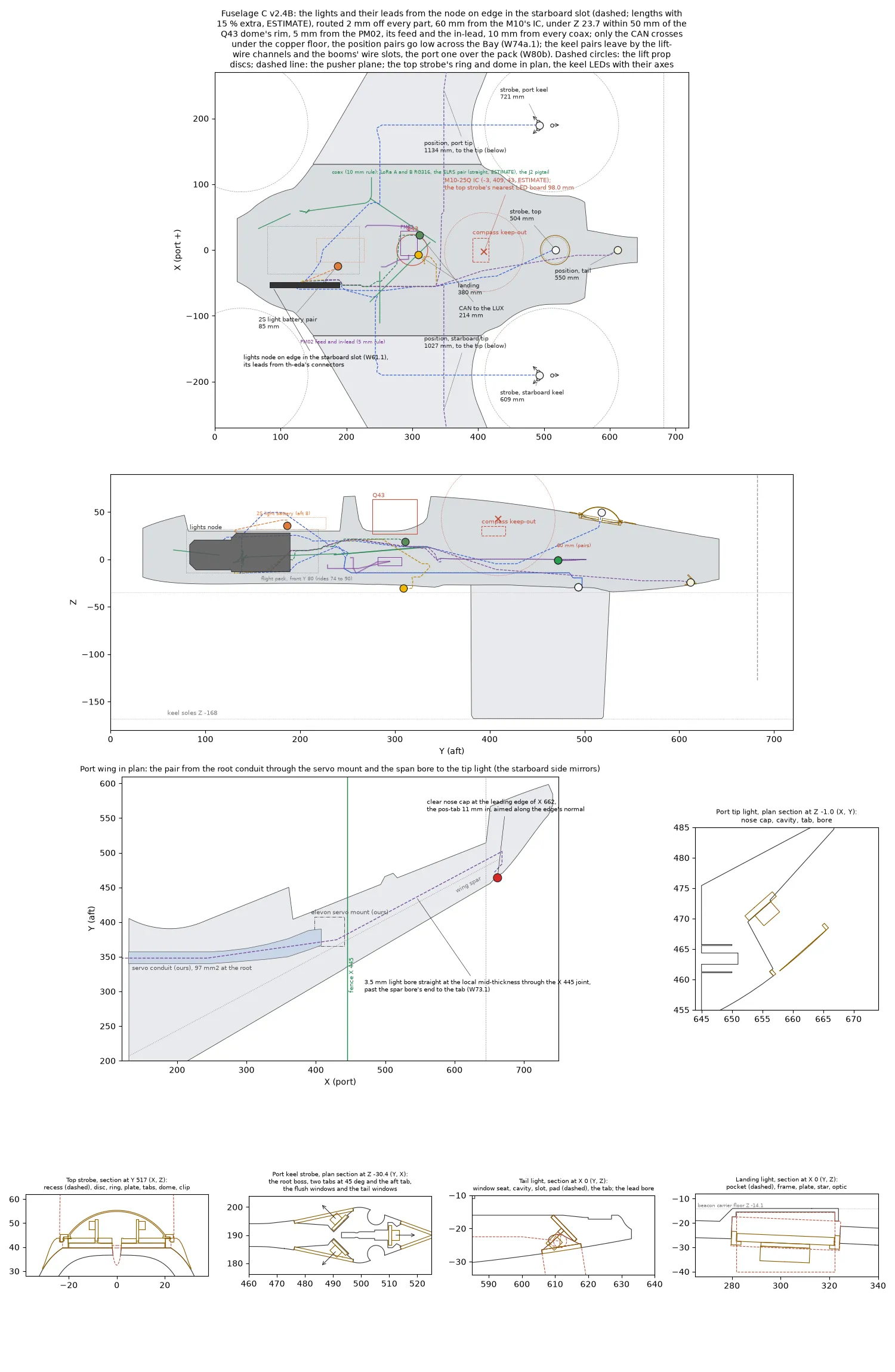
The top strobe is a clear low dome (40 mm chord, 25 mm sphere radius, 10 mm high) over six bare XP-L with horizontal axes,
because th-eda’s intensity model showed that a translucent printed dome fails the 100 cd horizon minimum (it shows only
about 280 mm2 of itself at the horizon: six XP-L at 2 A gave 52 cd effective). The dome is a bought acrylic low dome or
0.5 mm clear PETG formed over the printed buck (Strobe Dome Buck, the dome’s inside with a 10 mm flange and nine
vacuum holes). th-eda’s figure for the clear dome at the horizon is 532 cd at 2 A, 106 cd effective (ESTIMATE). The LEDs
stand on their tabs on a hexagon of 9 mm apothem, not the 13 mm th-eda asked for: the 40 mm dome’s inside is only
6.5 mm up at r 11.7, and at 9 mm the LED’s top corner has 2.0 mm of clearance. The emitting centres are 4.25 mm above the
skin plane, 1.25 mm above the clip ring. The tabs stand in slots in a PETG plate on a 40 x 2 mm 6061 disc (6.7 g), the
disc their heat path, their feet set on it in th-eda’s thermal adhesive on a 1 mm shim (th-avionics’ edge rays, below);
a 100 x 100 mm patch of aluminium foil tape goes on the skin’s inside under the top disc (th-eda), from Y 458 to 558, so that it stops 2 mm forward of the Bay/Tail joint. The coverage of the
sky by the two domes, cast from every LED against the whole aircraft, is in docs/lights-coverage.csv and
docs/images/lights-coverage.png. The disc and plate sit inside a PETG ring faired to the skin; the
dome’s flange (trimmed to 2 mm) lies on the ring’s 1.5 mm lip and a PETG clip ring with three snap fingers traps it, so
the dome comes off for the tabs. The dome stands 11.5 mm above the skin plane at its apex, the clip ring 1.5 mm (parts/review/lights-mounts-v24b.json, checks/strobe). Under
the dome are about 7.5 cm3 of air; the dome’s outer surface is about 16 cm2 and the lip and clip band about 4 cm2. Each
dome runs at about 1.8 W average in every state (node script v1.5), 2 W at most; th-eda checks the heat path.
The airframe set the places. The Bay’s roof is a ridge: at Y 525 it falls 2.2 mm by X +-18 and 5.8 by +-24, and at Y 470 only 0.8 and 2.4, so the top strobe was first at Y 470. W14 (th-telemetry, 2026-10-11) moves it aft to Y 517: the strobe’s LED boards must be 100 mm or more from the SEN0697’s IC at (0, 404, 34.0), as for an ESC body, and at Y 470 the nearest tab was 59 mm from it. Y 517 is the first seat where every tab, LED and pad is 103 mm or more from the IC: 104.0 mm to the nearest, the foot of a forward tab, and 106.8 mm to the nearest LED (measured; the IC’s position is an estimate, good to about 5 mm). At Y 513 the nearest tab is 100.1 mm. The roof falls 1.96 mm by X +-18 and 5.16 by +-24 at Y 517, so the ring and its fairing stand up to 6.1 mm over the skin at the sides (2.7 mm at Y 470). The fairing’s sides go out from 27.5 to 31 mm from the centre to make the flank less steep, and its aft point comes in from 44 to 38 mm, so the ring ends at Y 554.4, 5.7 mm forward of the Bay/Tail joint. The roof slopes 10.2 degrees nose-up there, and the ring’s plane follows it; the disc’s seat is a flat recess 4 mm under the skin at the ring’s centre, with 2.95 mm of LW left under it. The lead hole comes out under the roof at about Y 516, Z 37, 10.4 mm from the ESC hatch’s Lucid (measured to the reference model). The crest over the Q43 is 18.6 mm above the LEDs, 4.9 degrees up: at the horizon the forward sector (azimuth 330 to 30 degrees) is shaded by the roof ahead and is clear from 6 degrees of elevation up. The LED axes point 10.2 degrees up ahead and 10.2 degrees down aft. th-avionics’ edge rays (10 degrees below the top dome’s LED centres, over the ring and the skin to r 60) asked for a 0.5 to 1.0 mm LED rise at azimuth 60 to 75 and 285 to 300, so every strobe tab on the dome stands on a 1 mm aluminium shim. At Y 517 the -10 degree rays need 0.5 to 2.0 mm more at azimuth 55 to 65 and 295 to 305 (the roof rises ahead to the crest); the keel LEDs see those cells, and the shim stays at 1 mm. The belly dome on the payload cover (Y 491.3, between the cover’s three screws) is withdrawn: the payload cover keeps only the Survey3W lens and its five screws.
Keel strobes (W6.1 and W11, 2026-10-11)
Section titled “Keel strobes (W6.1 and W11, 2026-10-11)”Each keel carries three of th-eda’s strobe tabs in a root boss on the Keel B Mount, the port keel’s parts from
tools/make_keel_b.py (figure docs/images/keel-strobe.png), the starboard keel’s their mirror: two behind a flush
window in each face, and since W11 one facing aft behind the tail windows. The six XP-L are in series on the node’s
STR_B channel (th-eda). The side tab face centres are at X +-4.77 off the keel’s centre plane, Y 492, with the LED
centres at Z -30.4; the LED axes are horizontal and 45 degrees forward of the face normal (th-avionics): the port keel’s
outboard LED aims 45 degrees to port of ahead, its inboard LED 45 degrees to starboard, across the centreline. The two
side tabs stand as a chevron, apex forward, 4.6 mm apart at their inner ends, with the keel’s cable chamber between
them, because a tab turned 45 degrees cannot also stand back to back on the centre plane.
Each side window is a flat slot of 1.0 mm clear sheet on a 0.5 mm lip, flush with the skin (W11, th-aeronautics: flush
before a groove). Its aft end is W6.1’s 12 mm disc, centred on the face at Y 491.2, Z -30.4; it runs 9.5 mm further
forward along the face, its forward end square with 2.5 mm corners, so it spans Y 476.1 to 497.1 and Z -36.4 to -24.4
(12 x 21.5 mm). The LED’s ray toward the nose, 12 degrees to the skin, leaves through the slot’s forward part at about
78 degrees from its normal, where a flush pane passes about 44 % (th-avionics: enough, the nose gap is below the
horizon). 8.5 mm of run (W6.1’s estimate) was not enough: the wedge’s smooth join to the airfoil lifts the skin up to
0.1 mm over the slot’s forward end, and the -10 degree ray then met the seat’s edge; a round forward end cut the -16 and
-18 degree rays. The LED sees 50 degrees forward of its axis through the slot. Nothing stands proud of the boss and there
is no recess: W6.1’s bent window, its recess and its bending jig (tools/make_window_jig.py) are not needed. The window
is cut from flat sheet; the inboard window is the same part turned over. W6.1’s groove option (the bent window kept and a
flow-aligned groove cut ahead of it) would see the nose at 45 degrees instead of 78; the CSV gives both incidences.
The aft tab (W11) hangs head-down on the keel’s centre plane, its LED axis straight aft (th-avionics), the LED face at Y 510.8 and the LED centre at Z -29.95 (the tab at Y 509.8 to 510.8, Z -32.45 to -23.7), under the lift motor shaft’s hole in the pad. It fits nowhere else: ahead of Y 509 the forward motor screws’ columns (r 3.05 at X +-6.7, Y 505.3) leave no room, and aft of Y 512 the 20 degree closure leaves less than 1.5 mm of PETG outboard of its pocket; its pocket (1 mm wider than the tab each side, for the pair round the tab’s edges to its pads) keeps 1.69 mm to both. On the centre plane, its straight-aft ray meets the skin only at the trailing edge, so a flush disc on one face of the closure cannot see azimuth 175 to 185 (ESTIMATE before the run). The closure keeps its 20 degrees (th-aeronautics), and its two faces from Y 514.2 to the trailing edge are the window: the TAIL WINDOWS, two flat pieces of 1.0 mm clear sheet, flush on the closure’s straight faces, from Z -27.4 (the pad fillet bends the face above Z -27.15) down to a bottom edge that slopes from Z -34.0 at the forward edge to -39.0 at the trailing edge, forward corners r 2. Their inner faces meet on the centre plane at Y 525.2; each is 12.4 mm along the face, cut square and then its aft edge bevelled to lie on the centre plane (20 degrees to the sheet), and the two are bonded together there and on their lips. The four pieces of an aircraft are one outline. The aft LED sees azimuth 180 at 70 to 73 degrees from a tail window’s normal (about 0.67 through the pane, th-avionics), 170 and 190 at 62 to 64, 140 and 220 at 38 to 41, down to -30 degrees of elevation. Nothing stands proud.
The keel is 5.3 mm thick at Y 490 under the pad, so the Keel B Mount grows a root boss: the kit pad’s own footprint (its plan at Z -23, with the pad’s underside chamfer filled) carried down from the pad, then faired into the blade’s section by Z -42 with a smootherstep. W11: the boss is full width down to Z -36.5 from 1 mm ahead of the slot’s forward end (Y 475) aft past the side windows (their bottom edge is at -36.4), rising to -34.4 at the aft tab (its pocket’s floor is at -32.75) and falling again under the tail windows to their bottom edge, -39.1 at the trailing edge; ahead of the slot the fairing’s top rises to Z -25 over 10 mm. The flank reaches 70 degrees under the side windows (69 in W6.1) and 53 at the aft tab (a flat -39.1 from Y 512 gave 73 there). In plan the boss is a 12 degree wedge from the airfoil at about Y 469 to the window’s aft edge at Y 497.5, 19.8 mm wide at most; from there its slope blends over 5 mm into a straight 20 degree closure that reaches the trailing edge thickness at Y 526.5, the pad’s aft edge, so the boss’s tail runs 6.5 mm past the airfoil’s trailing edge under the pad (W6.1). The 12 degree widening is what a flush window needs: a flush pane of uniform thickness has its seat plane parallel to the skin, and with the LED axis 33 degrees off that plane the tab’s outer end then keeps 2.2 mm of PETG outside it. The lofted facets turn 15 degrees or less between neighbours (the mesh’s own faceting is 2 to 4), except at a crease of up to 20 degrees under the pad where the closure meets the pad fillet within 3 mm of the pad’s underside. Nothing changes below Z -42: the blade, the sole and the keel’s lowest point (Z -168) are as before, and th-hangar’s heel face rule (nothing at Y 520 within 23 mm of the sole) is far below. The boss adds about 7.0 cm3 of PETG (5.7 in W6.1), 3.0 g a keel sliced (3 walls, 30 %; 35.98 g against 32.98 g for the Keel B Mount; 2.7 in W6.1), and about 157 mm2 to the keel’s frontal silhouette, the same as W6.1 (ESTIMATE: the boss’s added depth is aft of its widest station). Two scallops of r 3.05 at the forward lift motor screws (X +-6.7, Y 505.3) keep the heads and a driver reachable through the boss; the same check found the 2026-10-10 Keel B Mount’s pad fillet already 27 mm3 into those heads. The thinnest PETG between any strobe pocket, cavity or channel and the air is 1.59 mm (measured).
The side tabs hang head-down from the pad: each foot sits in a slot in a 2 mm aluminium heat strip (th-eda’s heat rule) that lies in a channel under the pad over the tab, 3.2 x 4.8 mm, rises 1 mm thick through a 1.3 x 3.4 mm slot in the pad and lies flat on the pad’s top for 7 mm, 0.15 mm under its face, where the lift motor’s base clamps it (th-eda: a thermal pad in the gap). The strip’s exposed area ahead of the motor base is about 15 mm2 a tab and the clamped area under the base about 7 mm2 (ESTIMATES, base r 13), not the 10 x 15 mm of exposed strip th-eda asked for: the four motor screws take the pad’s underside at X +-6.7, the cable chamber and the sleeve’s end take the pad’s top ahead of Y 494, and the keel’s faces beside the windows are the windows. The aft tab’s strip is 3.2 mm wide (th-eda’s width): leg 1, 2 mm thick, over the foot at Z -25.7 to -23.7 (half in the pad’s underside, 1.6 mm under the shaft hole’s floor) from Y 511.2 forward to 505; leg 2, 1 mm, up through a slot in the pad at Y 505 to 506 between the forward screws (the shaft hole begins at 506.5); leg 3, 1 mm, forward on the pad’s top from Y 506 to 502.4, 0.15 mm under its face and aft of the side strips’ ends. About 15 mm2 of it is under the motor base and none in the air (ESTIMATE, base r 13); the foot’s slot holds 3.2 of the foot’s 7 mm. The motor base is the heat sink. The tabs and strips are 41 mm from the LoRa coil’s axis (35 or more), 35 from the LoRa jack (20) and 102 from the ELRS dipole (80), all outside th-telemetry’s keep-outs.
The strobe pair has its own channel (W6.1; th-main and th-telemetry: the riser is full). It leaves the cable chamber’s aft end at Z -29 through a 3.4 mm round channel on the keel’s centre plane, runs 4.5 mm aft to Y 497.5 round a 1.7 mm corner, then 10 mm straight up through the pad into the Keel B Mount’s open cable trough on the pad’s top (Y 493 to 497, from the kit pad), which leads forward into the VTOL spar’s end behind the end stop at Y 486. It never passes the jacks. The channel keeps 2.3 mm of PETG to the air and 2.0 mm to the strip channels, slots and recesses (measured). The aft tab’s pair (W11) runs in a 3.4 mm channel on the centre plane at Z -29.2 from the tab’s pocket forward 10.2 mm into the same slot at Y 499.6, where the L lead also rises; it is 50 mm from the coil’s axis, 41 from the LoRa jack’s top and 113 from the ELRS dipole.
To assemble a keel: solder the twisted pairs to the tabs’ pads and set each foot in its strip’s slot with th-eda’s
thermal epoxy on the bench. Side tabs: pass the strip through the window hole, lift it into its channel under the pad
and up through the pad’s slot, and fold its top over aft onto the pad; pass the tab, tilted 15 degrees, through the
window hole and set it in the strip’s slot; fish the pair aft through the cable chamber and up its own channel into the
trough. Aft tab, before the tail windows go on: lift its strip straight up out of the tail’s cavity through the access
well under leg 1 (X +-1.8, Y 504.8 to 509.6) until leg 2 stands through the pad’s slot, and fold leg 3 forward onto the
pad; pass the tab through the tail opening and set its foot in the strip’s slot; fish its pair forward through its
channel into the slot and the trough. Then take the pairs forward into the VTOL spar with the charge lead, bond the side
windows on their lips and the two tail pieces on their lips and to each other at the mitre, with epoxy (no hot glue).
A type 43 bead goes on the pair where it enters the keel (th-telemetry). In the coverage grid below the requirement
band (elevation -10 to +2), the nose cells and th-avionics’ aft sector (azimuth 135 to 225, elevation -2 to -30) are
reported per light and for the set; docs/lights-coverage.csv gives, for each cell, which keel LEDs see it, through
which window and at what incidence, and for the side LEDs the incidence W6.1’s bent facet would have (the groove option).
The wing is nowhere thick enough for a standing 10 mm star: within 6 mm of the leading edge the airfoil is 4.4 to 7.6 mm thick at every station from X 480 to 708. The position lights are therefore th-eda’s pos-tab (6.0 x 6.5 x 1.0 mm aluminium, the XP-E2 4.5 mm up, the foot 1.5 mm in a 1.1 mm slot; EDA 6c46420), standing behind a flush clear window. The tip tab stands in our own Wing Tip, 11.0 mm in from the leading edge along the edge’s normal at X 662, where the leading edge is at Y 463.8; the tab centre is (654.7, 472.0, -2.9) and the LED centre (655.8, 470.8, -1.0), port side, the starboard side mirrored (th-blender W73.1 28d08041, W73.2 46ed9e5b). The tip is 10.36 mm thick at the tab. The LED is aimed 41.4 degrees outboard of dead ahead and 6.0 degrees below the horizon (aim vector 0.6575, -0.7461, -0.1045), so its 120 degree lobe covers -18.6 to 101.4 degrees in plan. It shows through a clear PETG nose cap, “Position Light Window (tip) (own section)”, one part for each side. The LW over the tab’s top is 2.32 mm and over the XP-E2 2.58 mm; under the slot it is 0.81 mm (rule 0.8) and under the XP-E2 3.32 mm. The tab’s foot stands on the LW slot floor, with no aluminium pad (the night-only rule stays). The lead runs in a 3.5 mm light bore at the local mid-thickness: through the panels from the servo pocket’s end wall, straight through the butt joint at X 445 (our wing has no tongue pocket there) to the tip’s root, then in the tip past the spar bore’s end at X 663 by 3.75 mm to X 668.5, and forward to the tab. Its least clearances are 2.91 mm to the upper skin and 1.74 mm to the spar bore in the tip, and 3.71 mm to the nearer skin and 1.39 mm to the spar bore in the panels. The tail cone’s aft face is the pusher plate’s recess and its flanks face outboard, so the white tab stands behind a flush 12 x 1.0 mm clear window in the cone’s underside at Y 612, its axis tilted 35 degrees aft of the surface’s normal: 46 degrees below the aft horizon, so the 120 degree lobe reaches 14 degrees above it. Its foot stands on a 10 x 10 x 1 mm aluminium pad in the slot’s floor, 4.5 mm of LW from the pusher bore’s floor and 2.1 from the belly; the cavity’s corners are 1.6 mm from the belly. Its lead runs in a 4 mm bore inside the Tail at X -8 from the Bay’s aft cavity (1.0 mm of LW under its last leg, 3.5 to the pusher bore’s floor), clear of the lock screw holes and the pusher leads’ channel. The belly near the CG has 12 mm of LW only under the beacon carrier (Y 280 to 324), so the landing light pocket is there, its ceiling 1.4 mm under the carrier’s floor and the plate 1 mm proud of the belly; the 3.2 mm plate takes 0.2 mm off the fin headroom (8.8 to 10.5 mm) and moves neither the plate’s proud face nor the optic.
th-eda’s lip rule for the strobe: nothing opaque may stand over a ray 5 degrees below the LED centres, which crosses 2.7 mm above the skin plane at r 18. The ring’s top is at the plane and the clip ring is clear, so the rule holds. The tip light’s tunnel gives an orientation light with a narrow vertical lobe, not an anti-collision light; the strobes carry Part 107.29.
| Light | Part (PETG unless stated) | Where | Mass, solid (g) | Lowest Z, or frontal area | Lead from the node (mm, ESTIMATE) |
|---|---|---|---|---|---|
| Position, port | Position Light Window (tip) (own section) (clear PETG nose cap) 0.07, Wing Tip (own section) LW 7.84 (ESTIMATE, th-blender W73.2); the pos-tab with its XP-E2 about 0.2 | The tab 11.0 mm in from the leading edge of X 662 (Y 463.8), aimed 41.4 degrees outboard of ahead, 6.0 below the horizon; lead in the 3.5 mm light bore through the wing panels and the tip | 0.07 and the tip | Nothing proud; 0 mm2 | 1,134 |
| Position, starboard | The same parts, mirrored (the starboard cap is its own file) | X -662 | 0.07 and the tip | 0 mm2 | 1,027 |
| Position, tail | Position Light Window (tail) 0.1; the pos-tab and the 10 x 10 x 1 aluminium pad about 0.5 | Flush in the tail cone’s underside at X 0, Y 612, aimed 46 degrees below the aft horizon; the window’s edge 25.6 mm ahead of the motor bell | 0.1 | Z -26.5 (the belly’s own line); 0 mm2 | 550 |
| Anti-collision, top | Strobe Ring (top) 4.5, Strobe Plate 3.1, Strobe Clip Ring (clear PETG) 0.9, the clear dome 1.3 (0.5 mm PETG, 1.5 mm skirt); the 6061 disc 6.7, six tabs with LEDs about 1.5, six 1 mm shims | The Bay’s roof at Y 517 (W14; was Y 470) in a 4 mm recess, the ring’s top flush at the centre, Y 484.5 to 554.4; LED centres at Z 47.4 to 50.4, the apex at Z 55.4 | 9.8 and about 9 | 890 mm2 of its own, 91 mm2 added to the hull’s silhouette (the crest hides the rest; at Y 470 754 and 78) | 504 |
| Anti-collision, keels | Keel B Strobe Window 0.30 each, flat 1 mm clear sheet, four an aircraft; Keel B Strobe Tail Windows 0.14 each, two a keel; the root boss on the Keel B Mount 3.0 a keel sliced (3 walls, 30 %); three strobe tabs with LEDs about 0.76 and three aluminium heat strips about 0.50 a keel | The side tabs at X +-4.77 off each keel’s centre plane, Y 492, LED centres Z -30.4, behind flush slots Y 476.1 to 497.1 in both faces; the aft tab on the centre plane at Y 510.8, LED centre Z -29.95, behind the tail windows on the closure from Y 514.2 | 1.8 of windows an aircraft and about 4.3 a keel | Nothing proud, no recess; the boss adds about 157 mm2 a keel to the keel’s silhouette (ESTIMATE) and runs to Y 526.5 under the pad; nothing below Z -42 | 721 port, 609 starboard |
| Landing and pad | Landing Light Frame 7.7, the aluminium plate 14, star and optic about 3 | The Spar Box’s belly, the pocket Y 280 to 324, the optic at Y 302 | 7.7 and 17 | Z -36.4 (the optic, 1.6 mm below the payload cover’s plane); 300 mm2 | 381 |
The lead lengths are taut paths on a 2 mm grid of Fuselage C v2.4B’s free space, 2 mm or more from every part, with 15 %
extra length (th-blender W74a.1 925e4b2b; the keel and landing rows W80b 70cf9653 and W80b.1; ESTIMATE). The keep-outs are the pack over its slider travel, the light
battery, hub A’s pad with the two Micro BECs, the Lucid’s bracket, the LUX deck and the Q43 Seat’s footprint. Each lead
starts at its connector on the node’s edge (th-eda, parts/lights-node-envelope-v24b.json). The compass distances are
to the M10’s centre at (-3, 409, 43). Every coax is a 10 mm obstacle: LoRa A, LoRa B with its parked plug, both ELRS
coaxes (straight placeholders, ESTIMATE) and the J2 pigtail (th-telemetry).
| Lead | Node connector | Length, mm | To the M10, mm (rule) | Least coax gap, mm | PM02 / feed / XT90-to-PM02 lead, mm (rule 5) | To the Q43 dome, mm |
|---|---|---|---|---|---|---|
| Strobe, top | J10 | 504 | 60.9 (60) | 10.4, ELRS A | 47.5 / 34.1 / 81.2 | 34.8 |
| Strobe, port keel | J11 | 721 | 177.9 (60) | Shares the keel coax’s channel and the VTOL spar’s bore for about 240 mm (accepted, conditions below) | 50.1 / 82.2 / 28.9 | 65.1 |
| Strobe, starboard keel | J11 | 609 | 179.0 (60) | Shares the keel coax’s channel and the VTOL spar’s bore for about 240 mm (accepted, conditions below) | 70.1 / 39.5 / 81.9 | 67.3 |
| Landing | J14 | 381 | 90.8 (60) | 10.6, ELRS A | 15.4 / 23.2 / 43.0 | 33.7 |
| Position, port tip | J7 | 1,134 | 76.7 (60) | 10.8, ELRS B | 34.8 / 29.6 / 43.8 | 30.4 |
| Position, starboard tip | J7 | 1,027 | 91.0 (60) | 11.1, ELRS A | 47.7 / 29.6 / 81.1 | 33.9 |
| Position, tail | J7 | 550 | 60.4 (60) | 11.1, ELRS A | 47.7 / 29.6 / 81.1 | 33.9 |
| 2S light battery, 18 AWG | J2 | 85 (101 with its 16 mm travel loop) | 223.4 (60) | 70.2, LoRa B | 101.2 / 69.1 / 75.2 | 92.4 |
| CAN to the LUX, GH-4, twisted as bought | J3 | 214 | 104.3 (40) | 6.4, ELRS B, its last 5.5 mm | 15.8 / 17.4 / 18.9 | 5.2 |
The seven light leads are 4,926 mm together. Each lead was checked against every part along its whole length (W80b), and no point of a lead is inside a part. The keel pairs reach their channel mouths inside the keel coax’s keep-out by construction, as every coax to a keel ends there. The landing pair goes through the Landing Light Frame’s lead notch and under the plate to the star’s pads (ESTIMATE). Every other rule is met, with one exception: the CAN lead’s last 5.5 mm into the LUX’s CAN port is 6.4 mm from the ELRS B placeholder. The port itself is 8.9 mm from that line, so no route can meet 10 mm there. th-telemetry accepts it as a short approach at the port, because the CAN lead is a twisted low-current data pair, and th-main dresses the ELRS B coax 10 mm or more clear of the port where it can. The top strobe pair, at 60.9 mm, and the tail pair, at 60.4 mm, are within 2 mm of the 60 mm rule: th-main’s harness holds them at 63 mm or more with a tie point, and bench check 3 decides them. The landing pair’s last 20 mm are under the copper floor’s footprint, 42 mm below the floor, because the light’s pocket is there. th-telemetry accepts it: keep the pair twisted right into the pocket. The position lights are routed from J7, the lead to the wing-root driver board, which is not drawn yet. If that board gets its own connectors, the tip and tail rows change at the node end only.
Each keel strobe pair shares its keel’s 20 mm channel and the VTOL spar’s 12 mm bore with that keel’s ELRS and LoRa coax for about 240 mm. That is the only way out to the keel, and th-telemetry accepts it: the strobe pulse’s energy is from kHz to a few MHz, far below 915 MHz and 2.4 GHz, and the receivers’ front ends reject it. The 10 mm rule stays for the bay. Its conditions:
- The pair keeps its twist, a 15 mm lay or tighter, the whole way. It is untwisted only for the last 15 mm at the LED board.
- In the channel and the bore the pair lies on the side of the lane opposite the coax where the lane allows, never coiled around it, and is tied there in the channel.
- The gate is a link bench check, both keels, with the strobes at their night setting against the strobes off: the
ELRS link quality and RSSI must change by less than 1 dB, and the LoRa RTCM packet loss must not rise (th-telemetry,
antennas.mdbench tests).
No strobe feed runs outside the VTOL spar.
The CAN lead crosses over the front spar at Y 276 to 282, Z 21.5, under the Q43 Seat’s copper floor, 5.2 mm from the dome’s base and below the Z 23.7 plane (th-telemetry 479b82ca). Its conditions:
- The GH-4 stays twisted as bought, with no untwisted length under the dome.
- A zip tie around the front spar at about X -30, outboard of the Lucid Edge Bracket, holds it down. The lead’s other end is held by its connector at the LUX.
- The loaded GNSS noise test, with the strobes flashing, is the gate.
The top strobe’s nearest board element is its forward XP-L LED, 98.0 mm from the M10 (tab plates 98.5, solder pads 99.1; th-blender W74a.1). That is in th-telemetry’s accepted band: 100 mm is the target, 90 to 100 is accepted, and the M10 gate’s M4 decides. The aluminium disc (87.7 mm) and the PETG plate and ring are passive parts, not boards. From the conduit mouths the tip pairs follow the Wing Inner’s servo conduit (97.4 mm2 at the root face, 96.6 mm2 at its least section, th-blender W73 851d43db) to the elevon servo’s pocket; the servo lead and the pair take about 10 mm2 of it. The generator tests every route point against the LW and reports any that lies in solid outside a bore.
Filament dowels join the bonded LW parts: three vertical dowels through the top ring’s fairing collar into the Bay’s roof at (0, 541), (+-21, 504.5), 5.9 to 6 mm into the LW (W14; at (0, 494) and (+-21, 458) for Y 470, now filled); four cross dowels through the landing frame’s side walls into the Spar Box at Y 288 and 316. The windows are bonded (PETG to PETG, epoxy); the tabs stand in their slots, their feet set in th-eda’s thermal adhesive. The generator’s log gives every station. The masses are solid volumes times density (PETG 1.27, 6061 2.70, LW 0.60 ESTIMATE) except the keel boss, which is sliced; the slicer’s infill makes the rings lighter. The buck (21 g solid) is a forming tool, not flown.
Open points: th-aeronautics must take the frontal areas and the new masses (about 10 g of PETG strobe parts, 7 g of
disc, 14 g of plate, about 6 g of stars, tabs, strips and LEDs, and 5 g of keel boss, before leads) into cg.md and the
drag, and see the keel boss (12 degree wedge, 20 degree closure, 70 degree fairing flank under the side windows, W11’s tail windows); th-eda must check the top
dome’s heat path into the disc at about 1.8 W (node script v1.5) in every state (2 W cap), the keel tabs’ path through
the strip into the motor base at 0.4 W an LED (2.2 A, three a keel, the aft tab’s 3.2 mm strip included), the position stars’ heat in their LW pockets (0.7 to 1.1 W at full
current, on 1.66 mm of LW at the tip) and draw the strobe-tab; th-hangar sees nothing below Z -42 from the lights (the
keel soles stay at Z -168); th-main settles the pair in the keel’s riser; the node’s place sets the real lead lengths;
and a forward-facing tip light waits for a smaller board.
Source: docs/lights.md in the repo. Edit it there; this page is generated.
Comments
Comment on the whole page here, or on one section or step with the button beside it.