
The hangar
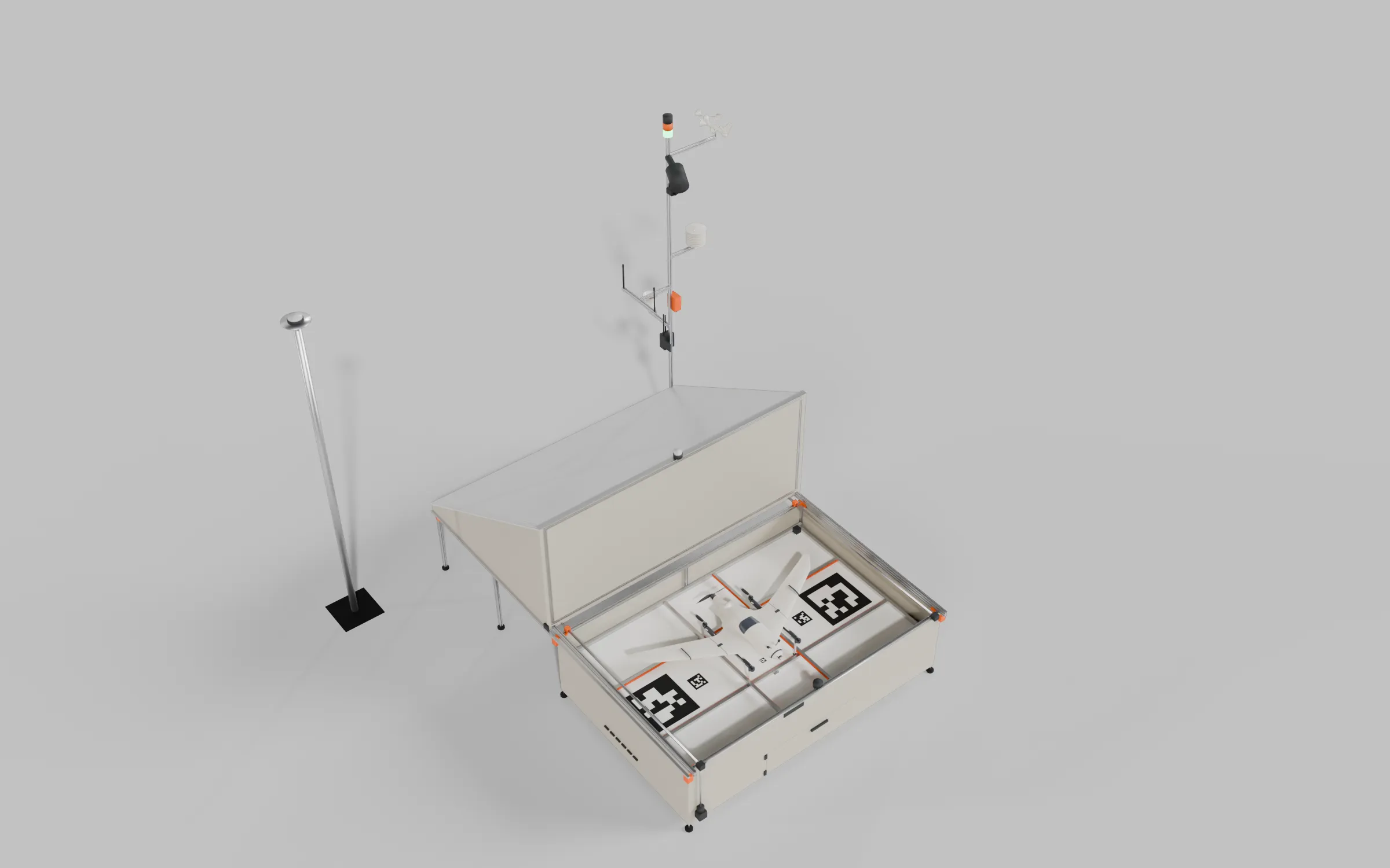
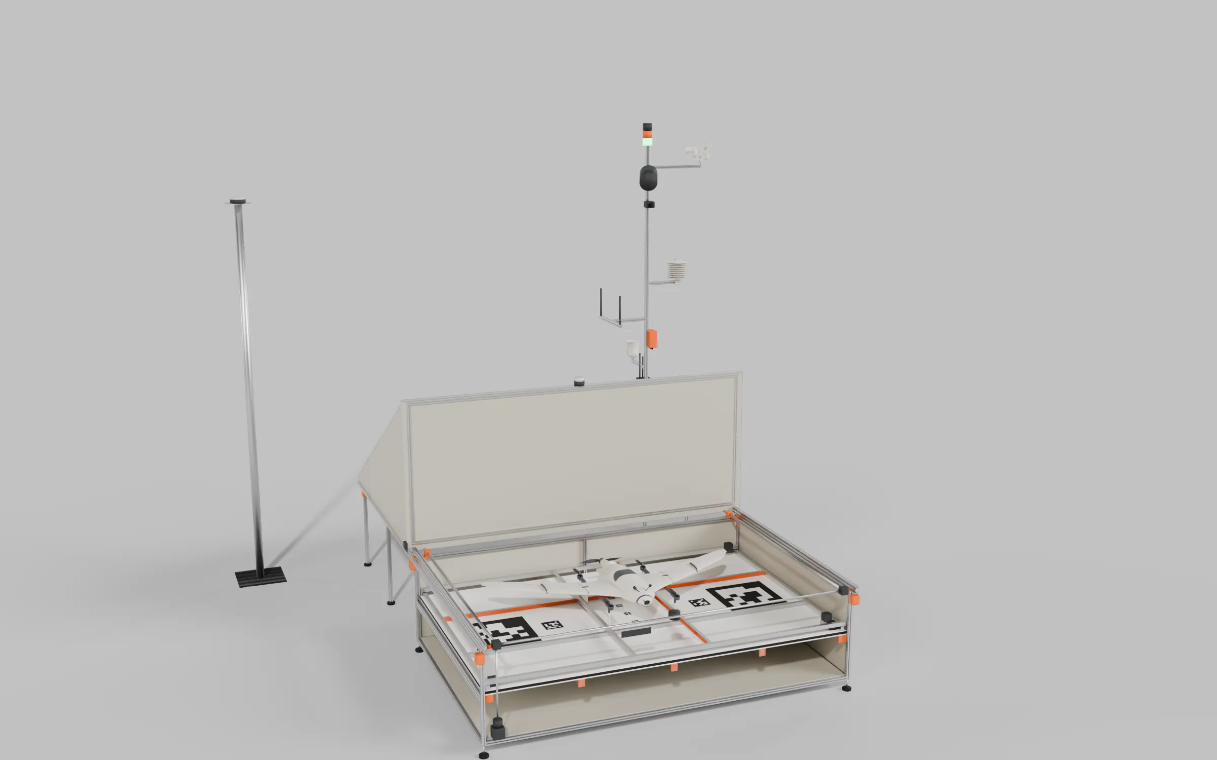
A low outdoor dock for the TerraHawk. The roof opens and the aircraft lands on a charging pad. After touchdown the roof closes and the pack charges through the landing feet. Nobody has to plug anything in. The frame is 20-series aluminium extrusion joined with printed parts. The whole design is generated by tools/hangar.py, so every size in this document comes from one set of parameters at the top of that script.
Design priority. When the aircraft’s needs and the hangar’s conflict, the aircraft wins (Ryan, 2026-09-29). The aircraft flies, so mass, drag, stability and landing behaviour cost it in the air; the hangar sits on the ground, where size, mass and parts are cheap. So the dock adapts to the aircraft: a wider capture, backstops, stronger bars or a bigger box before any change to the gear or the airframe, and a request to the aircraft side only for what costs it nothing measurable.
blender -b --factory-startup -P tools/hangar.py -- --drone-blend blender/terrahawk-scenes.blend \ --out blender/terrahawk-hangar.blend --render-dir blender/renders/hangar [--pathtrace]That builds the chosen design, the roll-off roof. The two alternatives that were modelled on the way stay in the script: --roof gable --tag clamshell for the hinged clamshell, and --roof lean --roof-pitch 30 --tag lean for the lean-to. Their renders carry those suffixes.
The aircraft is appended from the file tools/blender_scenes.py writes, so build that first. Pass --drone-blend blender/terrahawk-scenes-green.blend for the green colourway. Running without --factory-startup also works, but the Blender MCP addon then tries to connect to its bus on every headless run.
| View | File |
|---|---|
| Closed | blender/renders/hangar/h1-closed.png (and -cycles) |
| Rolled open with the aircraft docked | h2-open.png (and -cycles) |
| Roof mid-travel | h3-opening.png |
| Cutaway: bay, screws, cross shaft | h4-cutaway.png (and -cycles) |
| Plan, including the rails | h5-plan.png |
| Where each foot may land, and the markers | h6-pad-zones.png |
| Keels on their soles, squared by the closed push bars, close-up | h8-detail-keel-contact-cycles.png |
The plain renders use Blender’s Workbench engine and the -cycles ones are path-traced. To path-trace one scene per Blender run, which keeps memory down, add --pathtrace --only h1 (or h2, h4, h8, comma-separated).
Size, and why
Section titled “Size, and why”The aircraft measured from the STL pack is 1484 mm across the winglets and about 640 mm from nose to pusher prop. It stands on four printed foot blades that are part of the VTOL Motor Mounts. Each blade tip is roughly 4 × 11 mm, and the four tips sit at X ±190 mm and Y 68 / 484 mm, which makes a 380 × 416 mm rectangle.
The inside of the hangar is 2000 × 1300 mm, and the walls stand 250 mm above the pad on all four sides. The outside footprint of the box is 2044 × 1344 mm. The roof is a single 30° slope that falls toward the back of the box, with its tall front edge 1141 mm above the plates. To open, the whole lid rolls off the back onto a pair of rails, so the footprint including the rails is 2044 × 2832 mm. With the lid open nothing stands taller than 250 mm within 1.4 m of the pad, and the parked lid never passes over the drone.
The charging pad
Section titled “The charging pad”4d7beb2, 3 m/s from 353°, SITL's own Dryden gusts (seed 21), through the box's CFD wake. How it was flown, and the other films. Soundtrack, off until you unmute the player: Grieg, In the Hall of the Mountain King (Musopen Symphony, 2012; public domain), from Wikimedia Commons. Flown by ArduPilot; the logo on the title card is the project's own, used under CC BY-SA 3.0.The aircraft lands on a flat pad, and the dock then moves it onto the contacts (Ryan, 2026-09-28). Landing precision was the reason. With gusts modelled realistically (Dryden), th-testpilot’s hover-then-descend landings settled 56 to 155 mm off the aim in calm air and 0.2 to 1.5 m off in gusts, the aircraft knowing its position to 3 cm but not holding it, and a touchdown gate at 0.3 m captured 1 landing in 10. The earlier guide troughs caught only ±120 × ±137 mm. The walls allow more than that: a wingtip meets a side wall only at 213 to 258 mm of sideways offset. So a flat pad that lands anything the walls allow, and then squares the aircraft mechanically, fixes calm-air landings in this box. Gusty landings need a wider box as well; that waits for real gust-hold data, and until then the turbulence limit keeps the dock to calm air.
Surface. 15 mm of closed-cell EPDM sponge on the deck under a 3 mm white UHMW-PE sheet, the tags inlaid flush in black UHMW so a sliding sole does not wear them. The sponge takes the touchdown; the UHMW is what the soles slide on, at a friction coefficient of roughly 0.15 to 0.25 against the soles (estimate), so moving the 2.59 kg aircraft takes about 4 to 7 N.
Push bars. Two pairs of 20 mm aluminium bars, each with a rounded TPU 95A face strip over its full contact height, because the keel’s shell is one-wall LW-PLA about 0.45 mm thick and a bare bar edge would dent it long before the keel’s root noticed the load (th-aeronautics). The along-box pair moves in y, 3 to 23 mm above the surface, on low rails along the side walls: the front bar closes onto the front faces of the stilt soles and the rear bar onto the rear ends of the keels, which squares the heading as well as setting the position fore and aft. They close symmetrically about y -2.5, from ±572 to ±249 mm, a 324 mm stroke. The across-box pair moves in x, 29.5 to 49.5 mm above the surface, on rails along the front and rear walls, from x ±520 to ±209, a 311 mm stroke, onto the outer faces of the stilt and keel blades. The two pairs cross in plan, so they work in separate height bands. The low bars pass under a hanging pusher blade, which can sit 41 mm up between x ±127, with 18 mm to spare, and the across-box bars never enter that band at all. Each axis has two NEMA 17 steppers, one at each end of its rails, on TMC2209 drivers whose stall sensing stops a bar on contact and homes it. The drivers run from the bay’s 12 V supply: their absolute maximum is 29 V, so never from the 36 V charger supply (th-eda).
Sequence. After touchdown and disarm: close the along-box bars, then the across-box bars, back each off 2 mm so the gear is not clamped, then raise the pins. For a launch the bars park first; the pins stay up to carry the 12 V site-clear level until the aircraft is airborne, then drop. The bars move only while the aircraft’s HEARTBEAT, no more than a second old, says it is disarmed; the dock reads that flag rather than trusting a timer after touchdown. If the aircraft reports landed but is still armed 10 s after touchdown, the dock does not centre: it alerts and waits, because arming during a centring move would drag a spinning aircraft sideways. ArduPlane disarms by itself after a VTOL landing and never re-arms by itself, and a new arm needs the 12 V clear level, which the dock raises only after the bars are parked (th-avionics).
Contacts. Two pin blocks, one under each keel’s charge strip at the charge position the bars square the aircraft onto; the front soles carry no plate, so there are no front blocks. Each block is a 14 mm FR4 strip with one centreline row of 8 gold pogo pins at 14 mm pitch, 98 mm end to end, which leaves 7 mm at each end and 1.25 mm at each side of the 8 mm plate with the aircraft within ±2 mm. Each keel’s strip is split in two on that row (Ryan, 2026-10-11): the flight-pack segment from Y 392 to 476 under the first six pins, a 4 mm insulating gap, and the lighting-battery segment from Y 480 to 508 under the last two, L+ on the port keel and L- on the starboard one. Because the bars square the aircraft to ±2 mm before the pins rise, every pin stays at least 3 mm from a segment edge. At the default 3 A flight charge each of the six pins carries 0.5 A, 0.83 A at the bridge’s 5 A limit; the two lighting pins carry about 0.33 A each at the 0.65 A lighting charge. The block sits on a TPU cushion on a lift plate, and two hobby servos under the deck, one near each end so the long block rises level, turn cams to top dead centre to raise it, where they hold without power. Lowered, the pins sit 0.5 mm below the surface, so the soles slide over the openings. Raised, the cushion presses the pins into the plate at about 3 N a keel, under half of the 6.7 N each rear foot carries, so the pins cannot lift a foot.
Capture. With the heading within ±10°, the centre of the foot rectangle may land within ±193 mm sideways (238 mm straight in), 274 mm forward and 142 to 147 mm aft of the aim point. The aft figure assumes the folding pusher’s trailing tips; with the fixed APC pusher flying since 2026-10-04 the winglets or the prop disc set it instead (aft_capture_fixed_prop in the landing window). On Fuselage C (v2.3, and the v2.4B first build, whose stretch is ahead of the wing only), the pusher sits 40 mm further aft, its hub and blade band reaching Y 686.7 and the M5 prop nut on the hub’s aft face reaching Y 691.7 (th-blender, 2026-10-15; the nut’s 5 mm height is an estimate until it is measured, and a nylock would reach 692.7), which brings that to 227 mm straight in (the nut sets it up to about 2° of heading; 232 mm before the nut was modelled; th-simulator’s re-score of the recorded dock landings found none newly outside, and the furthest aft first contact in the sets the current harness writes is 112 mm, ecd49698) and 222 mm at 5°, while the winglets still set 196 mm at 10°; the gear and the wing are unchanged, and C’s lowest body part is the landing light’s optic, 132 mm above the ground line (th-blender, 5e789f7). The belly strobe moved into the keels (Ryan, 2026-10-11): flush 12 mm windows in each keel’s root boss at Y 491, Z -36 to -24, about 80 mm above the band where the across-box bars press the blades, and clear of the heel faces, the soles and their charge strips. The furthest aft clean touchdown so far, 140.5 mm, leaves about 92 mm. The folding window has almost no margin: across th-testpilot’s 148 clean dock landings the furthest aft touchdown was 140.5 mm at the feet centre, 1.5 mm inside the folding pusher’s 142 mm (th-simulator, 2026-10-07). On Fuselage C a folding pusher would trail 40 mm further still, leaving an aft capture of about 102 mm, less than landings already use. So if the folding pusher returns, two things come before docking it: measuring its folded tips, which th-blender models at Y 753 rather than the 777 the window assumes (about 24 mm more), and, if that is not enough, lowering the middle of the rear wall, which lifts the aft capture to about 290 mm. Sideways it is the wingtips against the side walls, less 20 mm; aft, the folded pusher tips against the rear wall, less 20 mm; forward, the parked front bar, 5 mm clear of a sole. That bar is also the forward backstop: a headwind slides the aircraft forward after contact (below), and the bar parks where it stops a sliding stilt toe with the nose’s airspeed tube still 25 mm from the front wall, which is what sets the forward capture at 274 mm rather than the wall’s 335. The first build is Fuselage C v2.4B (Ryan, 2026-10-13): the nose 6 mm longer with the ESC behind the pack. Its forward-most point is our own 4 mm total tube beside the camera, pitched 7° tip down, the upper lip of its mouth at X −18.0, Y −25.5, Z 14.2 (Ryan 2026-10-19, th-blender W104, 888383ba). It replaced the MS4525 kit tube, whose tip was at Y −30.4 in the same place (W93.2), on the top centreline at Y −30.8 before that, and earlier at X −16.55, Z 20.73. Because the tube is 18 mm off the centreline, a yawed landing swings it forward on one side, and the window counts that (2 mm at 10°). The rest of the nose is final for print (th-blender, 2026-10-14, aero/fuselage-c/v24b-internals.json). Nothing in it sits lower than the earlier belly (th-blender). The v2.3 nose’s pitot at Y −24.8 gave 275 mm, the earlier PT40 pitot at Y −10 gave 289 mm, and the 30 mm longer nose that Ryan considered (tip Y −49.8) would have given 250 mm. Every millimetre that the forward-most point moves forward moves the parked bar a millimetre aft and takes a millimetre off the forward capture. The forward capture is still more than the aft capture (227 mm straight on, 196 mm at 10°), so the aft side sets the window; the forward capture would meet it with the tip at about Y −72. th-simulator re-scored 2,318 recorded dock landings against the 275 and 250 mm forward captures without new flights (2026-10-12, 7dc0b6ec, sim/dock_rescore.py). At 275 mm no cleared landing is newly outside. At 250 mm one more is: an older band set at 3 m/s from ahead, 1.5 mm beyond. So at v2.4B’s 274 mm no recorded cleared landing is newly outside: the one beyond 250 mm came down 251.5 mm forward, and the next 234.5 mm. th-simulator re-scored all 8,113 recorded dock landings (2,576 cleared and inside the other limits) against 269.3 and 274.1 mm when the tube changed (2026-10-19, 647072eb): the same landings fall forward of both, so no recorded result changes. In the sets the current harness writes, the largest forward first contact among 219 cleared landings is 96 mm. These are first-contact positions. A slide after contact is what the parked front bar stops, so the capture holds where the aircraft first touches. The first dock sets on the Fuselage C model (th-testpilot, 2026-10-18, b9b5632f and 5aa00a04, with the airspeed sensor’s port error modelled) captured 14 to 15 of 20 D1x landings against 13 on the earlier model, and the axis brake ended much closer to the axis point (D1x median 7.5 to 9.5 m against 19.5 m; band sets 3 to 4 m against 8.5 to 9 m). Across all 104 dock landings in th-testpilot’s re-baseline on that model with the airspeed sensor modelled (2026-10-19, 4fa36c21), the brake stopped a median 4 m from the axis point and 31 m at most, 97 landings captured, and the dock refused none. parts/hangar/landing-window.json carries the limits for every heading, and tools/hangar.py checks on every build that a sole anywhere in the window stays clear of the parked bars. h6-pad-zones.png shows each sole’s capture area. Scored on this capture, th-simulator’s keel re-fly (2026-09-29, docs/agent-threads/hangar-aero/) puts the 95th-percentile miss at about 100 mm sideways in calm air, well inside, and at about ±350 mm sideways and 280 mm aft for gusty wind at 3 to 5 m/s from ahead or across. Those two figures are what a wider box would have to take.
The pad takes the gear’s dimensions from the committed gear parts, not from copies: tools/gear_dims.py measures them into parts/gear.json, and tools/hangar.py derives the bars, the pin strips and the capture from that file, draws no gear of its own, and stops if the aircraft file lacks the real keel B (Ryan, 2026-09-30). The across-box bars’ underside sits 5 mm over the soles’ tops, 24.5 mm as measured.
What the gear needs. th-blender added them (918e7e0): a vertical PETG heel face at the rear of each keel sole at Y 520 and a toe face at the front of each stilt sole at Y 53, both over the 3 to 23 mm band, since the soles’ turned-up ends would have let a low bar ride under them (docs/keel.md, “Push faces”). th-aeronautics: the across-box bars push the blades sideways at 29.5 to 49.5 mm with about 5 N, inside the gear’s 10 N design side case; and the final descent returns to a normal speed, at most 0.5 m/s: with the lift motors still carrying the weight, the sponge’s 3 to 5 mm of useful stroke keeps a level touchdown to about 160 N in total at 0.5 m/s, where 1 m/s would be about 650 N (th-aeronautics, 2026-09-28). On UHMW a drifting sole slides rather than grips, so the side load at touchdown is about a fifth of the vertical.
The guide troughs, superseded. The first pad funnelled the gear into four pin floors through printed PETG troughs, 45° superellipse bowls rising to 150 mm with a low inner lip, a floating pin block on a 16 mm TPU cushion in each floor. It needed the aircraft within about ±12 cm, which gusts took away, and its slopes put up to 140 N of side load into a front stilt root at a 1 m/s touchdown. It is still in tools/hangar.py behind --pad troughs.
The aim point sits 13 mm forward of the pad centre, and that is the result of three pulls. Wall clearance alone would put it 83 mm forward, because more of the aircraft sits behind its feet than in front: rotated 10°, the rear wingtip reaches 447 mm aft of the feet centre (the folded pusher, added later, 495 mm) while the nose reaches only 282 mm forward. In that analysis (2026-09-28) the furthest point forward was the earlier fuselage’s PT40 airspeed pitot, through the top of its nose cone: 286 mm ahead of the feet centre straight on, and 319 mm at a 10° nose-down touchdown. On Fuselage C v2.4B it is our own total tube beside the camera, its mouth at Y −25.5, 302 mm ahead of the feet centre straight on; its effect on the front push bar and the forward capture is given above. There it is about 182 mm above the pad, below the 250 mm wall top, and at the forward edge of the landing window its tip stays 61 mm from the front wall (63 mm at 10°). Nothing on the pad comes near it. But the front pair of lift rotors then hover only 1.3 rotor diameters from the front wall, inside the range where a wall roughens the ground cushion, while the rear pair sit at 2.1. Shifting the aim 100 mm aft puts both pairs at about 1.7 diameters, at the cost of fore-aft landing margin (±266 mm became ±166 mm), which the lateral window at ±125 mm was never going to use anyway. That was th-aeronautics’ recommendation in docs/agent-threads/hangar-aero/. Then th-simulator flew the approach from cruise with RTK-level GPS noise (20260927T190500Z): the stock position controller scatters about ±100 mm, and half the calm landings touched down 130 to 145 mm off. Sideways and forward that is inside the capture; aft, the folded pusher blades would have reached the rear wall at 132 mm. Moving the aim 30 mm forward, to -13, pushes that to 162 mm and leaves the lift rotors 1.61 diameters from the front wall and 1.74 from the rear, still balanced. So the pad does not need precision landing on the tags to accept RTK’s scatter; the tags stay the upgrade.
A ±125 mm landing is beyond plain GPS. The way to get it is to use the hangar as its own RTK base. A Quectel LC29H (L1 and L5) in the bay surveys itself in and streams corrections over the telemetry radio that the dock needs anyway; its antenna must be L1/L5 capable (th-telemetry). Its antenna is on a 48.3 × 4 mm galvanised steel scaffold tube in a concrete footing 0.7 m outboard of the starboard rail at the rail end, standing free of the hangar, with a ground-plane disc about 2.5 m above ground, a metre above the lid’s highest edge. The mast has to be stiff, because the rover is solved relative to the base and any sway of the base antenna goes straight into every landing: as a cantilever the tube’s tip moves about 1 mm in a 10 m/s wind and 4 mm at 20 m/s, inside th-telemetry’s 5 mm target, where a 2040 extrusion of the same height moves tens of millimetres. The footing matters as much as the tube, since a footing that rotates 0.1° alone moves the antenna 4 mm; a ground screw is not enough.
The base never moves. Before mapping starts, th-telemetry fixes the base’s coordinate once, from hours of raw logging post-processed against a CORS station, and it is never surveyed again; repeat site models are only comparable if the base stays where that coordinate says (th-telemetry, docs/site-mapping.md, 881b5dc). A base that drifts a centimetre moves every model by a centimetre. So the mast is built to hold still for years, not only in the wind:
- Free of the hangar. No brace or bracket joins the mast to the frame, which settles, takes the lid’s thrust and can heave with frost under its own feet. The tube meets the sway target as a cantilever on its own. (An earlier drawing braced it to the last outrigger post; that brace is gone.)
- Footing below frost. The concrete goes below the site’s frost depth, set at siting (the drawing shows 0.5 m), on undisturbed ground, and cures fully before the survey starts.
- Antenna fixed for good. The antenna sits on a 5/8-11 survey thread on a plate welded or pinned to the tube top, locked with a locknut and thread-locker and marked across the joint with a witness line, so a slipped or re-seated antenna is visible. Its height and orientation are recorded at the survey. Nothing else is mounted on the mast.
- Two check marks. Two survey marks in their own small concrete blocks, a few metres apart and clear of the hangar and the alternate point, let the aircraft or a handheld rover check the base later against its own corrections without re-surveying it. Their coordinates come from the same post-processing session as the base’s. The check rule is th-telemetry’s (
docs/site-mapping.md): occupy each mark with RTK for 2 to 3 minutes, before each mapping campaign, after a frost season or a storm, and monthly while missions are scheduled; each must read within 2 cm horizontal and 3 cm vertical. Both marks off the same way means the base moved: mapping stops, and the base gets a new, dated coordinate. One mark off means that mark moved. The 2.9 m beacon post, 2.6 m away, stands 9.6° above the antenna’s horizon, below the 10 to 15° elevation mask a GNSS receiver applies, and it is a few centimetres wide. That end is already the tall zone when the lid is open, and it’s 2.4 m from the pad, so the only tall pole on the site stands where the aircraft never descends. It stands outboard of the rail rather than on it because of the climb-out: in SITL an 8 m/s wind from ahead carries the climbing aircraft 3 m aft by the time it is 3 m up, which is over the rail end, and the mast top at 2.5 m above ground would then be under a wing. Outboard, the nearest wingtip passes 0.9 m from it. A base antenna needs a fixed sky view as much as a fixed position, and this spot gives it one: whether the lid is closed 1.4 m away or parked beside the mast, its top edge stays more than 35° below the antenna, under the ground plane, so the lid’s position doesn’t change the reflections the antenna sees. The mast’s own footing should be a concrete pad or ground screw, not the outrigger frame alone. The aircraft then needs an RTK-capable GPS in place of the standard module. That typically gives a few centimetres, and it also improves the geotags on the Survey3 mapping images. The markers below are the upgrade if RTK alone doesn’t hold the window; an IR-LOCK beacon was the original fallback, but its MarkOne V3 now lists at $2,949. The heading limit means weathervaning has to be off for the last few metres of descent (theQ_WVANE_*parameters), and the approach should run down the pad’s long axis. Both of those still need testing on the real aircraft.
The pad is built in four parts:
- Deck. A 6 mm compact HPL (phenolic laminate) sheet in matte white, laid over three 2040 joists. It’s rigid, stays stable in wet weather, is an electrical insulator, and is available in fire-retardant grades. It now carries the sponge and the UHMW sheet, which carries the markers.
- Surface. The sponge and UHMW sheet described above, in four or six sheets with their joints outside the gear’s capture areas.
- Push bars and rails. Four 20 × 20 bars on V-wheel carriages, four rails on the walls, GT2 belts and four NEMA 17 steppers, two per axis, driven by TMC2209s.
- Pin blocks. Two, one per keel: a 3 mm FR4 strip 14 × 120 mm carrying 8 gold pogo pins that stand 1 mm proud, a TPU 95A gyroid cushion under it, a lift plate, and two servos with cams under the deck. The pin leads flex about 6 mm at every lift, so they are flex-rated stranded wire with strain relief at both ends (th-eda). Each opening has a drain through the deck.
- Markers. Nine AprilTags inlaid in the surface, described next.
Landing markers
Section titled “Landing markers”The belly camera’s job is to see the aim point from a few metres up until the strip fills its view. Two constraints set the layout. The layout dates from the guide troughs, which filled the band x 130 to 360 on each side; on the flat pad the same places keep every tag out from under the parked push bars (x ±520, y about -625 and +610), so no bar hides a tag from the camera. And no one tag size covers the descent: a tag stops being detectable at roughly 24 times its width, but it also has to fit inside the camera’s view, which at 90° is about as wide as the aircraft is high. So there are three sizes, all tag36h11 (the family that OpenCV and the OpenMV camera boards both detect natively), and all in one frame with its origin at the aim point, so any visible subset gives the aim point.
| Tags | Size | Where | Detectable to | Reliable to | In frame down to |
|---|---|---|---|---|---|
| 10, 11 | 350 mm | side fields under the wings, x ±725 | 11 m | 4.5 m | 0.94 m |
| 20, 21 | 100 mm | x ±435, inboard of the parked across-box bars | 3.2 m | 1.3 m | 0.50 m |
| 30 to 34 | 36 mm | the strip, every 120 mm from 240 mm ahead of the aim point to 240 mm behind | 1.2 m | 0.5 m | 0.03 m |
The ranges assume a 90° camera, 640 px across, acquiring at 10 px per tag and reliable at 25 px; a wider or sharper camera stretches them. Read across the table and the coverage is continuous: the big tags carry the descent from RTK hand-off down to about a metre, the mediums the last metre, and the strip tags the touchdown. tools/make_pad_markers.py generates the set: parts/pad-markers/layout.json for the model, one SVG per tag at 1:1 mm with its quiet zone, and pad-layout.svg for the whole pad. The tags are black on the white deck, matte both, so there’s no glare to fight; for a prototype they’re printed on matte outdoor vinyl, for the durable version laser-cut 2 mm black HPL inlaid flush. Nothing on the pad is shiny except the pins.
The camera side, the small computer that recognises the tags and sends LANDING_TARGET to the plane_precland.lua applet, is the avionics session’s, in landing-sensing.md.
On the aircraft
Section titled “On the aircraft”The landing gear is keel B (Ryan, 2026-09-29, th-blender’s tools/make_keel_b.py and tools/make_stilt_b.py, 6367863), shaped for drag first, the gear having been about 15% of cruise drag (th-aeronautics). Each front foot blade gets a printed stilt, 8 mm thick across the aircraft and 20 mm along it, on a 16 mm canoe sole from Y 53 to 83 with a 2 mm edge radius and no contact plate; its only job on the pad is the vertical toe face at Y 53. Under each rear spar hangs a keel, a 9 mm streamlined blade from Y 380 to 520 webbed to the spar, on a canoe sole up to 20 mm wide with elliptical ends, a 2.5 mm edge radius and a vertical heel face at Y 520. Each keel sole carries the charge plate, a flat 8 × 116 mm strip on its centreline from Y 392 to 508, of 0.5 mm nickel-plated brass bonded into a 0.5 mm recess, its lead soldered to the back at Y 478 between two pin points (Ryan, th-eda, 2026-09-29; solid metal rather than FR4 because the soles slide on the UHMW at every landing and would wear through an ENIG flash): plus on one side, minus on the other, as before, since the aircraft’s ideal-diode bridge accepts either polarity. Keel A, the first version, had 30 mm square soles with a plate on every foot. Keel A is retired from the print beds (Ryan, 2026-10-11, th-main f55e944), so the first aircraft prints with keel B, the gear the dock is drawn for. The gear exists for the pusher prop before it exists for charging. The original gear stood the aircraft on 48 mm feet with the pusher axis at the datum, so a rigid 10 × 7 pusher, stopped at a random angle, would reach 79 mm below the feet and strike whenever it stopped more than 22° from horizontal, about three landings in four. The pusher was an Aeronaut CAM Carbon folding 10 × 7 (th-main, 4e24911), whose blades fold aft of the hub. Since 2026-10-04 it is a fixed APC 10 × 7E pusher for now (Ryan, 6656b24), so a blade can stop pointing straight down, and the gear is what protects it. The box takes either: the dock model carries both the spinning or stopped disc (radius 127 mm, at Y 640 on the earlier fuselage and Y 687 on Fuselage C) and the folded tips (Y 777), and checks on every build that a vertical blade clears the pad and that the low push bars pass under it with 18 mm to spare. The aft capture stays set by the folded tips, which reach further aft than the fixed blade, so it is conservative while the fixed prop flies and right again if the folding one returns. On the gear the aircraft stands 168 mm below the datum and clears a vertical 10 × 7 blade by 41 mm on any flat ground, and a 12 in blade by 16 mm. The tail body then touches at 46° nose-up, so the pitch limits at touchdown are the soles’ own angles.
Keel A’s contact plates were 1.6 mm FR4 boards with an ENIG gold finish; keel B carries the 0.5 mm nickel-plated brass strips described above instead, because its soles slide on the UHMW at every landing and would wear through an ENIG flash. Every plate is one charge pad.
Site clear on the charge pads. Ryan asked for CAN through the feet, so that the docked aircraft and the dock could talk without a radio. th-avionics, as owner of the flight bus, declined it (docs/agent-threads/gps/20260927T190246Z), and the reasons hold: an exposed pad pair on the bus that carries the airspeed sensor, GPS, compass and rangefinder is one wet plate from a stuck-dominant fault that stops every node at once, the stub would force the whole bus to 500 kbit/s, and a dock node on the flight bus could set the charge node’s relays, which is the trust boundary the aircraft-side interlock exists to keep. What the docked link was for is the pre-arm “site clear”, and that now travels on the charge pads themselves, with no new contacts or wires. The charge node already reports the voltage on its side of the pads as battery 3 at 10 Hz, so the dock signals with levels, each at a 50 mA current limit except charging:
| Pad supply | Meaning |
|---|---|
| 0 V | dock not ready, or no clearance |
| 5 V | probe: contacts good, charging may follow |
| 12 V | on the pad, lid open, site clear: launch permitted (the pre-arm script reads 11 to 13 V as SITE_CLR 1; the shoe diode-OR drops about 0.7 V, inside the band) |
| ramp above pack voltage | charging |
The pack can never reach the pads, and the charge switch stays open at 12 V because the interlock closes it only on the ramp, so 12 V on a wet pad is a small leakage and never a fault. A withdrawn clear reaches the flight controller within 200 ms. The radio SITE_CLR message stays as the airborne path for the landing hold, and as the docked fallback if th-telemetry’s trough test passes. The dock raises 12 V only once the lid is at its open limit switch and the radar guard is clear, so the aircraft can never arm under a closed lid, and drops it to 0 V on any loss of clearance or once the aircraft reports armed and airborne.
From the plates, wires run up the stilt and the motor mount to an LT4320-style ideal-diode bridge, then through a 10 A fuse to the main pack leads. A small 6S active balancer stays on the balance lead permanently, because the pad only sees the main leads. Once the aircraft lifts off, the bridge stops the pack from putting voltage on the plates, so a wet plate in flight is never live. Where the charge-node section below says “shoe”, it means this plate.
Charging logic
Section titled “Charging logic”The bay holds a Riden RD6006 programmable CC/CV module running from a Mean Well LRS-200-36. The dock controller (below) commands it over Modbus and reads the aircraft’s MAVLink telemetry through the dock radio. The pin floors are only ever energised through a handshake. First the aircraft must report landed and disarmed, and the roof must be closed. Then the controller sets the supply to about 0.3 V above the pack voltage the aircraft is reporting, with a 100 mA current limit. If that trickle flows, every contact in the path is good and the controller raises the current to the charge rate (3 A by default). If nothing flows, a stilt is off its floor. The controller then alerts instead of raising the voltage.
The pack isn’t left sitting full. By default the controller charges to storage voltage (3.85 V per cell, 23.1 V) and tops up to 25.2 V only when a flight is scheduled. The top-up holds the RD6006 in constant voltage at 25.2 V until the current tapers below 0.5 A, and only then stops. Do not stop it when the pack first reads 25.2 V: that is still the constant-current phase, and the cells then relax from the resistive drop (5 A × 0.045 Ω, about 0.04 V a cell) and the surface charge to about 4.10 to 4.13 V, under the 4.15 V the flight controller needs to count the pack as full (below). After the taper the cells settle at about 4.17 to 4.18 V (th-avionics, 2026-10-01). The drops in the pins, bridge and wiring fall with the current, so at 0.5 A the pack is within a few millivolts a cell of the setpoint (estimate). If the top-up ends with any cell under 4.15 V, the pack is out of balance: the dock alerts instead of launching. The alert names the low cell, from the per-cell voltages in BATTERY_STATUS for battery instance 1, the charge node. A spread over about 0.05 V between cells on a new P50B pack is a pack fault for the operator to inspect, not a reason to wait (th-avionics, 2026-10-01). The lighting battery. The aircraft’s 2S lighting LiPo (1300 mAh, 6.0 to 8.4 V; it also backs up the beacon board) is charged by the dock, not on board, because the on-board charger made about 2 W next to the LiPo with nowhere to shed it (Ryan, 2026-10-11, th-eda). It charges through the L segments from an isolated 2S constant-current, constant-voltage section on the hangar I/O board, a block of its own across an isolation barrier, driven through three optocouplers (enable, low current, charging status) whose defaults are off and low current, so a half-working I/O board can only charge slowly or not at all (th-eda, terrahawk-eda 46293c0, block lchg): a Traco TMR 10-1213WI isolated converter (1.5 kV) feeds an LT3652 charger that floats at 8.38 V and ends at a tenth of the set current, controlled over the board’s I2C through a PCA9536 at 0x41 (IO0 enable, IO1 0.65 A or 0.2 A, IO2 charging status), which comes up as charge off at low current after any reset; its output J40 (XH-2) carries L+ on pin 1 to the port keel’s two lighting pins and L- on pin 2 to the starboard keel’s; 8.40 V at most and 0.65 A (0.5C, which th-avionics advises as kinder to the pack than the 1C limit), about 1.5 hours from the 25 % reserve, inside the flight pack’s own top-up at the default 3 A; its output floating from the flight-pack charger and the dock’s ground, because L- is the aircraft’s ground while the flight-pack plates reach the pack through the ideal-diode bridge, and a shared ground would make the two chargers fight through the bridge’s FETs. The Rover board starts the lighting charge only with the aircraft docked and reporting disarmed, the pins up, the radio link live and every lighting cell under 4.20 V, reading the cells from BATTERY_STATUS id 2 (BATT3, voltages 0 and 1, which update at about 1 Hz), so it tapers the current as either cell nears 4.15 V rather than relying on fast feedback, by switching the charger to a low setting of about 0.2 A, and stops when any cell reaches 4.20 V or the link drops (th-avionics). Most charges end at the aircraft rather than at the charger: the lights node opens its charge input at any cell at 4.19 V (resuming under 4.15), which is the cell voltage the charger’s 8.38 V float approaches, so the current falls to zero and the charging status goes off before the charger’s own end-of-charge. The float must stay at 8.30 to 8.48 V at the keel L+ contact (8.40 V +0.08/−0.10, th-avionics, 2026-10-14). The aircraft’s lights node latches the dock’s charge off when it reads L+ over 8.65 V, and it reads to about ±2 %, so a float above about 8.48 V could stop charging on a healthy dock (lights_node.lua v2.1, 7dacf19e). Behind that, the node’s LM74800 trips at 8.76 V or more (th-eda, EDA 6b02229). After a latch the node re-arms when the dock withdraws its offer (L+ under 6.0 V) for 10 s, which the dock’s normal off-and-on between charges does. A second fault holds charging off until the node restarts, and the node reports both over CAN as “lights: dock over-voltage”. The LT3652’s divider (634k over 412k, 249.7k equivalent, which cancels the VFB pin’s 110 nA bias current as the datasheet directs) gives 8.378 V nominal. Its 3.3 V reference is 3.282 to 3.318 V (±0.55 %, specified at 25 °C only). With 0.1 % resistors the worst case at 25 °C is 8.32 to 8.43 V, inside the band. With 0.5 % resistors the low end falls to about 8.28 V, and with 1 % both ends fail. So the divider uses 0.1 % resistors, 25 ppm/°C thin film (th-eda, EDA d585f17: R59 634k Yageo RT0603BRD07634KL, R60 412k TE CPF0402B412KE1), and because the reference is specified at 25 °C only, the float is measured at L+ before the first unattended operation (see that list). The Rover treats that as a normal full charge: every cell at 4.15 V or more and the status off for a few seconds. It is a fault, reported to the GCS, when the status goes off with any cell under 4.10 V while the aircraft reports the dock offering charge (th-eda, th-avionics’ node v2.0). The aircraft guards itself as well, without being the charger: the lights node’s ideal diode on L+ keeps the segments dead off the dock, and opens on any cell at 4.20 V (closing again under 4.15), on an imbalance it cannot bleed, whenever the aircraft is armed, and (proposed) outside 0 to 45 °C. The 12 V site-clear level is only ever on the flight-pack segments.
Charging follows the pack’s own temperature, from the charge node’s 10k NTC on the pack, which reaches the dock as BATTERY_STATUS.temperature for battery instance 1 in centi-degrees (th-eda, docs/charge-node.md bac80fb). It starts only between 2 and 40 °C, pauses above 45 °C, resumes under 40 °C, and never starts under 2 °C. These are Ryan’s 45 °C ceiling (2026-10-06, via th-aeronautics) with th-eda’s 2 °C floor, one set of numbers that the dock and the aircraft’s charge interlock both use; th-eda’s looser 45/50 °C band, still inside the P50B’s limits, is Ryan’s to choose instead. A reading below -20 °C, above 80 °C or of INT16_MAX means the thermistor is disconnected, shorted or missing, which the analog backend does not flag: the dock treats it as unknown and does not charge. Every wait and pause is logged with the pack and bay temperatures. A pack lands about 10 to 15 K above the air after a full mission (estimate, th-aeronautics), so on a hot day it can arrive near the limit, and charging adds about 3.5 W at 1C; the cool-down is then part of the turnaround between missions, and the schedule allows for it. The heat that matters sits in the still air of the aircraft’s battery bay, around the pack, so a fan that only blows over the outside barely helps; from 50 to 40 °C the pack takes about 1.5 h on a 30 °C day and 2.5 h on a 35 °C day in still air, about 1 to 2 h with a fan over the outside, and about 20 to 45 min with air pushed through the bay (th-aeronautics’ lumped estimate, within a factor of 2). On Fuselage C there is no way to push air through the bay: the pack is sealed under the Hatch, and the belly’s NACA inlet feeds only the ESC channel, which is baffled from the rest of the bay against rain and dust (th-blender, 2026-10-12). So the pack-cooling jet that the dock had for the earlier fuselage’s belly louvre is withdrawn, with its blower, duct and nozzle. The cool-down is still air, about 1.5 to 2.5 h from 50 to 40 °C, and the turnaround schedule allows for it. A lower charge rate helps (about 3.5 W of heat at 1C, 0.9 W at 0.5C), so on a hot day the dock charges at 0.5C. If the turnaround matters more later, a vent into the pack bay is an aircraft change, for th-blender and Ryan. The lid may also stay open during the wait when the weather is in limits (no rain, the wind within the launch limits, the guard clear), since the opal polycarbonate slope lets in sun. After the first real landings, log the pack temperature’s decay and fit its time constant, so the schedule uses a measured cool-down instead of the estimate. The bay’s own sensor and the fan behind the port louvres keep their job, cooling the bay.
Inspect before charging after a hard event. A dented or crushed cell in the 6S2P Li-ion pack is a fire risk on charge. So the dock does not charge, and does not launch, after any of these until an operator confirms on the node’s page that a person has inspected the pack and the airframe: a GPS-loss landing (any STATUSTEXT that starts “gpsguard: GPS lost”, including the guard’s disarm text “gpsguard: GPS lost, landed; disarmed”), a tip-over disarm (exactly “tipguard: tipped over; disarmed”), a touchdown that did not end on the pad, or a roll or pitch over 45° while armed and on the ground. The dock reads the attitude from ATTITUDE, which the LoRa port streams at 4 Hz (MAV2_EXTRA1 4, th-avionics). The aircraft’s own radio reports its real buffer to the aircraft (Rx Snd RadioStat = ardu_1, params/board-luxf765.parm), so the aircraft’s ArduPilot can slow every stream on that port, ATTITUDE included, when the downlink fills. Packets lost on the link leave gaps too. The dock unit’s 1 Hz RADIO_STATUS (see “Radios and antennas”) throttles only the uplink, not this. How low ATTITUDE goes under the full RTCM load is not measured yet. So the 45° check counts time, not samples: over 45° for 1 s or more. A gap of more than 2 s in ATTITUDE reads as unknown, never as level, and an armed aircraft off the pad with an unknown attitude also sets the flag. The two guard texts are an interface: each script carries a line that names this page and says to tell th-hangar before the text changes (th-avionics, 61284ea). A STATUSTEXT carries at most 50 characters, and a longer text arrives in segments, so the dock matches the prefix in the first segment only, and the exact texts it keys on stay under 50 characters (“tipguard: tipped over; disarmed” is 31). The flag is kept on the Rover board and survives a reboot. The case behind it is a GPS loss in wind: the aircraft comes down drifting at the wind’s speed and, on turf or soil, can tip over (see “GPS loss near the pad”).
stateDiagram-v2
    [*] --> Closed
    Closed --> Opening: aircraft inbound, or launch requested
    Opening --> Open: roof at the open limit switch
    Open --> Centring: landed and disarmed
    Centring --> Closing: bars squared and backed off 2 mm, pins raised
    Closing --> Closed: roof at the closed limit switch
    Closed --> Probing: aircraft aboard, pins up
    Probing --> Charging: trickle current seen
    Probing --> Fault: no current, a plate off its pins
    Charging --> Holding: storage voltage reached, or 25.2 V and current below 0.5 A
    Holding --> Charging: top-up requested before a flight
    Holding --> Opening: launch requested, pack reported full, airspeed zeroed, wind within limits, charge stopped, pads at 0 V, bars parked
    Open --> ClearSignalled: at the open limit switch and guard clear, pads to 12 V
    ClearSignalled --> Open: guard trips, pads to 0 V
    ClearSignalled --> Closing: armed and airborne, pads to 0 V, pins lowered, launch complete
In ClearSignalled the launch has a fixed order: set the flight mode, then arm. The aircraft boots into QRTL on the pad, because its throttle failsafe fires before the receiver starts and then clears, and QRTL cannot be armed. So whoever launches, the dock controller or the operator’s GCS, first sets the launch mode (AUTO, or QLOITER for a manual hop), waits until the aircraft’s heartbeat reports that mode, and only then sends the arm command. The site node’s hold values keep the RC link up the whole time. th-simulator flew the full case in SITL (docs/agent-threads/hangar-aero/20260928T030000Z-th-simulator-dock-rc-gcs.md): hold values from the site node, a GCS launch in AUTO, a landing 1.4° off the box axis, and a re-arm 3 s later without a reboot. If the aircraft refuses the arm (a COMMAND_ACK that is not accepted, or no armed heartbeat within 5 s), the dock tries once more, then stops the launch: it sets SITE_CLR and the pads to 0, closes the lid, and puts the aircraft’s own PreArm: STATUSTEXT lines on the operator’s page, so the reason is visible. It never retries in a loop. A refusal can last until the aircraft reboots: a flight script that stops with an error makes the scripting pre-arm check refuse every arming (th-testpilot, 2026-10-12, a tip_guard.lua error), and only a power cycle clears it. The dock cannot power-cycle the aircraft, so that needs a person.
Before the launch, the pack must be full and the aircraft must know it. The flight controller counts the mAh used since boot and never counts the charge, so after a dock charge without a reboot its capacity failsafe would refuse to arm. th-avionics’ charge_interlock.lua (0aa48a0) resets the count to 100 % after a full charge: a charge seen, every cell at 4.15 V or more, and current under 0.5 A for 30 s. “A charge seen” is a latch, set by any current above 0.2 A since boot or the last reset, so the 30 s can run with the charger off. It then sends “charge: full, min cell X.XXV, battery count reset” to the GCS. The dock controller takes that message, or a clean pre-arm check, as “ready to launch”, and the Holding to Opening step waits for it. A storage charge does not reset the count, so a launch always starts with the top-up to 25.2 V; after a partial charge the aircraft refuses to arm with “low capacity failsafe”, which is intentional. The dock never reboots the flight controller to clear the count: a reboot restarts it at 0, which is correct only for a full pack, and a full pack has already reset it. A reboot also puts the aircraft back into QRTL on the pad.
The airspeed sensor’s zero is set at boot, and only then: ArduPilot averages the sensor for about 1 s after power-up and takes that reading as zero airspeed (th-avionics, from AP_Vehicle.cpp to AP_Airspeed::calibrate; ARSPD_SKIP_CAL 0 in our files). Wind on the airspeed tube in that second stays in every reading until the next boot, and because the dock does not reboot the flight controller, that is every dock flight. Wind from aft makes the airspeed read high, so the transition ends at a lower true speed: 4 m/s on the tube is about 10 Pa, about 2.8 % of the speed at the end of the transition (th-avionics, ESTIMATE). The open box makes that the likely direction. With the lid parked downwind, the air near the pad runs back toward the front wall at 0.4 to 0.8 of the free wind (th-aeronautics’ 2D CFD, see “Siting and heading”), and the tube’s mouth, about 182 mm above the pad, is in that layer, so an aircraft parked facing the front wall has the wind from aft. So a person who powers the aircraft up on the pad does it with the lid closed, or with the tube’s mouth covered, until the GCS shows “Airspeed 1 calibrated”. So the dock sets the zero again before every launch, in Holding with the lid closed, as the last step before Opening (th-avionics, checked in our ArduPilot copy, 4c98c922). It sends MAV_CMD_PREFLIGHT_CALIBRATION with param 3 at 1 and every other param at 0. Disarmed, the aircraft zeroes its barometer and starts the same 1 s airspeed zero as at boot. It replies MAV_RESULT_IN_PROGRESS at once, then a final COMMAND_ACK when the zero is done. The dock keys on that final ACK, not on the “Airspeed 1 calibrated” text, because the ACK is part of the MAVLink interface and a firmware update can change the text. ACCEPTED: the dock waits 5 s, so the flight controller’s own 5 s ground update also brings the EKF’s height datum to the new barometer zero, and then opens the lid. TEMPORARILY_REJECTED (no free task slot): it tries again. FAILED (no healthy readings from the sensor): it does not launch, and it puts the reason on the operator’s page. The aircraft sends the final ACK once, on the link the command came on, and a LoRa frame can be lost, so no final ACK within 5 s of the MAV_RESULT_IN_PROGRESS counts as a failed try and the dock sends the command again; a new command starts a new 1 s zero, because the first one has ended. After 3 tries with no ACCEPTED, the dock does not launch. th-avionics ran the command on the bench LUX F765 with no airspeed sensor fitted: IN_PROGRESS, the barometer texts, “Airspeed 1 not initialized, cannot cal”, then a final FAILED, so the failure path holds on the hardware; the success path is from the source only until the sensor is wired. Nothing on the aircraft filters the dock’s system id 200 for this command: the only filter, MAV_OPTIONS bit 0, is not set in our files, and th-avionics keeps the command and its ACK on the dock interface list. It fails closed in any case: until the zero is done the aircraft refuses to arm with “Airspeed: 1 pre-flight calibration in progress”, and after a failed zero with “1 need pre-flight calibration”. A zero before every launch does not depend on the dock seeing a reboot, and it is taken at the pad’s temperature of the moment, not at a power-up hours before; it costs about 1 s and one flash write. The dock also watches the boot time in the aircraft’s messages, and after a reboot it sees, it sets the zero again before anything else, as a second line. When th-avionics sets ARSPD_OFF_PCNT (after a bench check of the zero’s spread from boot to boot), the aircraft also sends “Arspd 1 offset change large;cover and recal” when a new zero is far from the last one. After a zero with the lid closed, that points to the tube or the sensor, for example water in the tube, so the dock then does not launch and sets the inspection flag (proposed; the text is ArduPilot’s and only a warning on the aircraft).
Dock controller
Section titled “Dock controller”Three boards, decided 2026-09-27 (Ryan, through th-lidar), built in two stages.
-
An ArduPilot board running Rover, H743 class, has all the authority: the lid drive, the radar guard over DroneCAN, the alarm relay,
SITE_CLRto the aircraft, and every interlock decision, in Lua. The condition attached is that Lua is never the last line of safety. Hardware limit switches cut the lid motor’s power directly at both ends of travel, a physical stop button is fitted, and a heartbeat relay drops out if the board stops running; “disarmed” means dock safe, every output dead. It speaks MAVLink over the 915 MHz telemetry radio that also carries the RTK corrections, logs to its SD card, and is tested in SITL beside the aircraft before it drives anything. Because it holds the dock link’s signing key, its firmware is a custom ArduPilot Rover build withHAL_STORAGE_BACKUP_ENABLED0: stock ChibiOS builds copy the whole parameter storage, the key with it, to/APM/STRG_BAKon the SD card at every boot, which would leave the key in plain files on the card (th-avionics,AP_HAL_ChibiOS/Storage.cpp, 2026-10-19). The same patch goes in the aircraft’s build. The board is a Holybro Pixhawk 6C Mini with Holybro’s PM02 V3 power module (proposed by th-hangar, 2026-10-19; in th-main’s parts list, ebe81648): the module takes the bay’s 12 V (its input is 2S to 12S, about 7.4 to 50 V), gives the board 5.2 V, and reports the 12 V rail’s voltage, and its current only roughly, because its 120 A sensing range reads coarsely at the dock’s few amps: an H743 whose definition is already in ArduPilot, so the storage patch is its only change from stock (th-avionics builds it), with an SD card and two CAN buses, which lets the people guard’s radar nodes have a bus of their own. Draft port map, for th-avionics’ build:Port Use USB The site node: MAVLink 2 through its mavlink-router. The site node holds no signing key, so the Rover board takes only requests from it and makes every safety decision itself TELEM1 The beacon board’s isolated TELEM port to the dock’s mLRS radio: MAVLink 2, signed, 115200 baud TELEM2 Spare CAN1 The people guard: the two radar AP_Periph nodes, alone on this bus CAN2 Housekeeping: the hangar I/O board and the weather node MAIN 1 The lid motor driver’s PWM, on a Script output function, driven by Lua only MAIN 2 to 6 GPIO outputs written by Lua only (IO co-processor GPIO 102 to 106): lid direction, the stepper drivers’ enable, the servo supply enable, the alarm relay, and the heartbeat pulse train MAIN 7, 8 Spare AUX 1 to 3 Inputs, read by Lua (GPIO 50 to 52): lid closed limit, lid open limit, stop button. The switches also cut power in hardware; the board reads them to know the state AUX 4 Input: the switched lid supply’s read-back, through a divider on the interlock board AUX 5 Input: the switched stepper supply’s read-back, so a welded contact on that pole is found the same way AUX 6 Spare The IO co-processor’s MAIN pins can only output, so the inputs go on the main processor’s AUX pins (th-avionics, from
AP_IOMCU.cpp). Every enable and relay is wired so that LOW is safe, because an IO co-processor reset and a board boot both give LOW. A script that stops without a reboot, however, leaves the outputs as they were, so the heartbeat is not a level: Lua toggles MAIN 6, and a hardware watchdog (a retriggerable timer) holds the heartbeat relay in only while the pulses arrive. The dock script toggles it at 10 Hz from its own update function, after that cycle’s checks have run, never from a separate heartbeat script, because ArduPilot stops only the script that fails, and a separate one would keep the relay in while the dock logic is dead. Scripts run late under load (up to 0.248 s on the flight controller in SITL, th-testpilot) and Lua’s garbage collector pauses too, and a 10 Hz toggle gives the timer one rising edge every 0.2 s, so the worst gap between edges is about 0.45 s: a short period would give nuisance stops. The watchdog and every hardware interlock (the relay, the stop button in series with its coil, and the limit switches’ wiring) are on their own small board, th-eda’sboards/dock-interlock, not on the hangar I/O board: the lid needs them from the first day it moves, before the I/O board exists, and the I/O board is by design the one with no authority (th-eda, 2026-10-19). The lid motor’s supply, the stepper drivers’ supply and the servo supply all pass through that relay, so a stopped script, a frozen board or a lost IO co-processor drops all three within the watchdog’s period, whatever the other outputs hold. The watchdog’s period is 1.0 s nominal (0.8 to 1.2 s with an RC timer’s tolerance, th-eda, so the supplies are off within 1.5 s of the last good pass), and the dock script toggles MAIN 6 only on the path where its loop does its real work each pass, never in an early return that still runs when the rest is stuck. A welded contact or a shorted coil switch would defeat the watchdog unseen, so the switched lid supply also comes back through a divider to AUX 4: at every boot and before each lid move, the script stops the pulses for 2 s and checks that the supply drops no sooner than 0.6 s and no later than 1.5 s, which proves the contacts open and the timer’s period at once. If it fails, the dock moves nothing and reports it. The stepper supply’s pole gets the same 2 s test through AUX 5. th-eda’s rev A draft (EDA 322deac,boards/dock-interlock/README.md) sizes the lid pole as an Omron G2RL-1A-E (16 A at 24 V DC, 1.7 times the 9.2 A stall) and puts the stepper supply (7 A fuse) and the servo buck’s input (7 A fuse, so that the hangar I/O board’s 5 A resettable fuse acts first on a jammed servo) on the two poles of a G2RL-2A (EDA c45fe76). Wiring that follows from it: the stop button has two normally closed contact blocks, one in the relay coil’s feed and one for the read-back on AUX 3, so pressing it or unplugging it both read as stopped; the lid feed from the supply has a 15 A fuse in the harness, because the board carries none on that path; the motor leads pass through the board, where each limit switch opens only its own direction with a diode across it; direction high on the G2 opens the lid, which is checked on the bench with the motor uncoupled before the switches are fitted; and the hangar I/O board’s stepper drivers get their own 12 V input from the interlock board (hangar-io J7, EDA 4a71594), so the relay can cut them alone. While that supply is off the stepper drivers do not answer, which the I/O board’s firmware expects. The G2’s single current-sense output goes to the I/O board’s LID_CS input (EDA e18dd68), which reads about 0.050 + 0.020 V per amp: 0.21 V at the 8 A limit and 0.234 V at the 9.2 A stall, and about 0 V while braking. The dock script subtracts the offset measured at rest and is calibrated against a clamp meter on the bench (checklist item 10), because Pololu calls the figures approximate. The bay’s supplies (2026-10-19, in th-main’s parts list, c4da4289): one 12 V supply, a Mean Well HLG-240H-12A (16 A, fanless, potted to IP65, universal 90 to 305 V AC input, so no voltage switch can be left wrong; LRS-200-12 as the fallback), feeds the lid motor, the stepper drivers, the electronics and the rail heat cable. At its limit it holds the current constant and lets the voltage fall, so an overload does not trip it but browns out the bay, the Rover board included. The budget therefore relies on a sequencing rule: while the lid moves, the stepper drivers are disabled, the pin servos are idle, and the heat cable and the lighting charger are off. The peak is then the lid at its 8 A limit, about 4 A of electronics (the site node with its accelerator, the PoE switch and three cameras about 30 W, the Rover board, the radios, the radars and the I/O board; ESTIMATE) and the bay fan: about 12.4 A, 22 % under the limit. Without the rule, a stalled lid with the pin servos moving could reach about 17 A. The pin servos’ 6 V rail comes from a Pololu D42V110F6 buck (6 to 60 V in, 6 V out, well over 6 A at 12 V in) on that 12 V, switched by the interlock relay; the flight pack’s charger keeps its own 36 V supply. Locked down in the build (th-avionics, 2026-10-19): the interlock and timing values cannot be changed over MAVLink: read-only in the firmware’s embedded defaults, or, if that flag does not reach the parameters the dock script creates (th-avionics tests it in SITL), constants in the script itself; no output has a stock function that a MAVLink command moves (no relay functions, noDO_SET_SERVOchannels, throttle and steering unassigned, so arming drives nothing); andMAV_GCS_SYSIDis the site node’s id withMAV_OPTIONSbit 0, which drops other system ids. That last step filters strays and is not authentication; the boundary is the site node, whose mavlink-router serves only its own localhost and the USB, never an open network port. -
The hangar I/O board, with no authority: th-eda’s
boards/hangar-io(terrahawk-eda 8ff740c) on a Waveshare ESP32-P4-Module (Ryan, 2026-10-06), in the bay beside the Rover board. It generates the push bars’ steps (four TMC2209s on one shared UART, stall sensing on each DIAG) and the pin servos’ pulses, but the Rover board holds the stepper drivers’ enable line and the servo supply, and enables them only in theCentringstate and the launch’s bar parking, so a fault on the I/O board cannot move a bar or a pin at any other time. The enable is fail-safe by its sense: the Rover must actively drive it to enable, and with the lead unplugged or the Rover unpowered the drivers stay disabled. The board is also the charger’s Modbus bridge (the RD6006’s TTL port, 3.3 V by its manual, to confirm on the unit before connecting) and the housekeeping I/O: the lid drivers’ two current-sense outputs, bay temperature and humidity, the bay fan with its tach input (the pack-cooling blower channel is spare since the jet was withdrawn), and the rail heat cable, a 12 V self-regulating cable so the whole dock stays low voltage (about 5 A, ESTIMATE, which the Rover keeps off while the lid moves so the 12 V supply is not overloaded). The P4’s WiFi coprocessor is held in reset, since the ELRS 2.4 GHz transmitter is a couple of metres away and the site node carries the network. The weather station is not on it: it has its own node on the post (“Weather station”). It reports to Rover over DroneCAN. If it goes silent, Rover counts that as a fault and charging stops. If the RD6006 needs only a few Modbus registers, Lua on Rover may cover it; that is decided on the bench. -
The site node, as in “Warning, voice and cameras”: voice, cameras and the network link. No authority over the dock; it is the aircraft’s RC source for every dock launch, and a remote pilot’s sticks pass through it.
Stage 1 is the Rover board alone with the hardware interlocks. Stage 2 adds the hangar I/O board when the charger is wired. Purchases wait for Ryan’s word.
People guard
Section titled “People guard”Five 24 GHz radars watch the ground around the hangar, and since 2026-09-27 they are the only people detection in the system: Ryan dropped the aircraft’s own radar pod for its drag. Near the pad, the dock’s SITE_CLR is therefore the aircraft’s only check for people before it arms and before it lands. Away from the hangar, a field takeoff relies on the pilot. The full review is in docs/agent-threads/hangar-people-guard/.
-
Coverage. One HLK-LD2450 at each box corner, looking outward, at Z 200 and tilted 10° down, kept under the wall top and within 70 mm of the wall so the lid’s skirts pass over them. A fifth on the far outrigger post, because the parked lid is a 1.14 m wall across the rear of the box and blinds the rear corners toward the rail zone exactly when the aircraft launches or lands. Each unit reads ±60° in azimuth to 6 m; the dock holds while any target is within 5 m of the pad centre.
-
Still people. The LD2450 tracks moving targets and may drop a person who stands still. With nothing on the aircraft behind it, this is no longer an edge case: pair each LD2450 with an LD2410C, which reports presence from breathing but no position, and hold if either sees someone. Test one pair on the bench, a person standing still for two minutes in front of it, before ordering five.
-
Interface. The radars sit on two AP_Periph nodes on the dock’s DroneCAN bus. The Rover board, as MAVLink system 200, sends
NAMED_VALUE_INTSITE_CLRat 2 Hz. Its value is the system id of the aircraft being cleared, 0 for not clear, and the aircraft accepts only its own id (th-avionics,docs/agent-threads/two-airframes/). There is one airframe (Ryan, 2026-10-04); the id check stays, so a second aircraft on the site could never be released by another’s clearance. The dock clears one aircraft at a time: the one reporting landed on the pad for a launch, or the one on approach for a landing, and never an approach while the pad is occupied. Docked, the aircraft reads the same clearance as 12 V on its charge pads (see “Site clear on the charge pads”), with the radio message as the fallback; in flight it is the radio message alone. The aircraft requires a fresh 1 within 3 s whenever it is within 10 m of the pad, both to arm and to begin a landing; no message counts as not clear. The dock can withhold arming, never grant it. -
Fail-closed layers. The lid does not open while the guard holds. The aircraft does not arm without
SITE_CLR. On approach it holds in QLOITER until clear for 5 s, for at most 2 minutes or until the battery reserve, then lands at the alternate point with the horn and beacon running. The abort is always a hover, never a go-around: neither the dock nor the landing hold puts the aircraft into a fixed-wing mode near the pad. On the critical battery failsafe (30 % or less) this is a hard rule (th-avionics,docs/failsafes.md, 5187772): a forward transition on a 31 % pack stalled at 15 to 16 m/s with the pack at 17 V in SITL. So at critical the hold is shorter: QLOITER over the pad until the guard clears, and if it does not clear within about 30 s, a sideways VTOL move to the alternate point and a VTOL landing there. The hover costs about 7.5 mAh a second, so the 30 s hold, the move and the descent take about 0.5 Ah (estimate), 5 % of the P50B pack. Above critical, the hold runs for up to 2 minutes, and less when the battery reserve comes first: the hold leaves atCTL_RESERVE_PCT36 %, which is critical’s 30 % plus the descent from the hold height and the move (th-avionics, e6252849). After a far return into wind it is less than a minute. th-testpilot’s worst return on the Fuselage C model, 1.5 km into 8 m/s, reached the hover over home at 41.9 %. The hold leaves when the charge drops below 36.0 % (below), 5.9 % later, which at S5’s measured hover current, about 34 A (714 mAh in 76 s, about 0.094 % a second), is about 65 s of hover from arrival. The first about 19 s of that is QRTL placing the aircraft over the pad, before the hold begins, so the hold itself lasts about 45 s (estimates; th-aeronautics, th-avionics). So a person clearing the pad after such a return has less than a minute, not two. The operator’s page counts down to whichever comes first: the 2-minute clock, or the reserve, estimated fromBATTERY_STATUS: the charge left above 36 % at the measured current (current_battery), not a fixed draw, because gusts and the heavier night build change it. The hold and the dock read the same number: the aircraft’s whole-percent remainder (capacity_remaining_pct, truncated), which is alsobattery_remaininginBATTERY_STATUS, so the hold leaves on the first reading of 35 and the dock sees that step about 1 s later, one message period on the LoRa link (th-avionics). Each whole percent is about 12 s of hover, so the countdown is good to about that. -
Alternate landing point. A flat, marked patch 12 m to starboard of the pad centre, abeam of it, kept clear for 2 m around (
alternate_pointinparts/hangar/landing-window.json; a default for the drawings, fixed at siting). Abeam and to starboard keeps it out from under the approach, which comes along the axis from the lid end, out of the take-off drift on the front and sides, and away from the RTK mast and the beacon post, whichtools/hangar.pychecks. 12 m puts it at least 5 m from anyone standing at the edge of the guard’s 5 m. No radar covers it, so the dock can never report it clear or guarded; the overview camera shows it to the operator, and the horn and beacon run through the move and the landing. The move to it is a VTOL move only. ArduPlane’s GUIDED is not one: setting a GUIDED target starts a fixed-wing leg even from a hover (set_guided_WPclearsvtol_loiter), so the landing hold never uses GUIDED to reach the alternate point. It stays in QLOITER and moves the aircraft with RC roll and pitch overrides from a position loop, at 2 m/s or less, as the yaw step does (th-avionics,docs/clear-to-launch.md, bd87901); the 12 m then takes about 6 to 10 s. The same check closed GUIDED in VTOL flight at critical incrit_guard.lua(d03f9df). The move gets a SITL check whenlanding_hold.luais written. -
GPS loss near the pad. The aircraft flies
gps_loss_guard.luav2.5.1 (th-avionics, adopted in 78449fb9, v2.5 in ecc674d2; v2.5.1 reports a loss of both receivers about 3.5 s sooner; v2.4e, 9c3e3d93, added the jam handling, v2.4f, d4f67ef4, lands the EKF-failsafe case, and v2.5 handles the second receiver) andtip_guard.lua(b6010ac, fixed in 3482dc7). After a loss of the GPS fix in VTOL flight, every mode that needs a position goes to QHOVER, which uses no position or velocity. If a pilot holds control (channel 12 above 1700 µs, see “Remote piloting”), the pilot flies and lands it. With no pilot, the script descends: full stick down (Q_PILOT_SPD_DN1.5 m/s, about 1.2 m/s measured) while the barometer reads more than 10 m over home, then 1150 µs (about 0.67 m/s) for the last 10 m, and it disarms after its own touchdown check with the text “gpsguard: GPS lost, landed; disarmed”. With no RC at all, QHOVER descends at 0.5 m/s and the same disarm applies. Earlier guards used QLAND, which acts on the velocity that the estimator keeps after the loss. From the moving approach it walked 24 to 366 m at up to 17 m/s and 34° of roll (v2.1 and the v2.2 candidate,docs/agent-threads/test-battery/), so v2.3 replaced it.In calm air on the TerraHawk model (measured on v2.3; th-testpilot’s v2.4e jam rows give similar figures), losses on the approach (in the hold, at the start of QRTL, 20 m and 5 m out, and over the box) came down 0.7 to 90 m from the pad, level at 0.61 to 0.82 m/s, and the script disarmed 3.9 to 4.2 s after touchdown. The limit is wind. QHOVER holds no position, so the aircraft moves with the air for the whole descent. In 8 m/s gusts from 50 m it took 58 s to come down and landed 387 to 468 m downwind of the point of loss, and −62 to +46 m across the wind, within about ±9° of the wind line (five seeds; th-testpilot, from the gpsguard-v23c logs). The downwind distance is about the wind speed multiplied by the descent time, so it grows with the height of the loss. In calm air the spread across the approach axis was under 7.5 m, and the touchdown moved up to 33 m along it, from the estimator’s creep.
The dock’s part: when the aircraft reports the loss (a STATUSTEXT that starts “gpsguard: GPS lost”, or no 3D fix on both receivers,
GPS_RAW_INTandGPS2_RAW), the dock runs the horn and beacon, as for a landing at the alternate point, until the aircraft reports disarmed, and puts the aircraft’s last position and the overview camera on the operator’s page. Nobody goes to the aircraft until it reports disarmed. The dock then does not charge or launch until an operator confirms an inspection (see “Charging logic”). Since 2026-10-15 the aircraft has a second receiver, a SEQURE M10 as GPS2 beside the Q43 (th-avionics, f7b6ae3f).GPS_RAW_INTalways reports the Q43, not whichever receiver is primary, so the Q43 failing alone shows no fix there while the aircraft navigates normally on the M10 (th-testpilot: QLOITER held with no drift). The dock treats that as a lesser alert, not a GPS loss: the Q43 is the RTK receiver, and the landing hold descends to the pad only on RTK fixed, so the aircraft cannot land on the pad and will go to the alternate point. The guard reports it as “gpsguard: GPS1 fault, flying on GPS2” and pins the M10 as primary, and later as “gpsguard: GPS1 back, primary restored” once the Q43 has been good for 10 s; neither starts with the loss prefix (v2.5). The dock takes either the guard’s “GPS1 fault” text orGPS_RAW_INTwithout a 3D fix whileGPS2_RAWhas one as this case, tells the operator “RTK receiver lost”, keepsSITE_CLRas it is (the hold refuses the pad descent by itself), runs the horn and beacon for the alternate-point landing as usual, and does not set the inspection flag. The notice clears on “GPS1 back” or whenGPS_RAW_INTshows a 3D fix again, because the guard does not send “GPS1 back” at a disarm. If the aircraft lands with the Q43 still lost, the notice stays up until the Q43 recovers, and the pre-launch pad check, which needs the Q43 RTK fixed, refuses the next launch until then, so a dead RTK receiver is found on the ground, not in the next approach. Both receivers’ messages reach the dock at 1 Hz (MAV2_EXT_STAT1, th-avionics). A Q43 cut alone always gives “GPS1 fault, flying on GPS2”, never a loss text, about 2 s after the cut (v2.5.1, th-testpilot’s J9). The reverse case is different: the M10 also carries the aircraft’s only compass, so an M10 cut with the Q43 good leaves navigation normal but loses the compass, and the guard sends nothing. The dock reads it from structured data, not text:GPS2_RAWwithout a 3D fix, orSYS_STATUSshowing the compass present but not healthy (a compass reads unhealthy within 0.5 s of its last reading; both messages at 1 Hz; th-avionics, from the ArduPilot source). It tells the operator “backup receiver and compass lost” and sets the inspection flag, since a dead M10 is hardware to look at. Without a healthy compass the landing hold does not take the pad: it goes to the alternate point at once, with no hold, because the aircraft’s yaw source is the compass and in a hover its yaw then runs on the gyro alone, while the box needs the heading within ±10° (th-avionics,docs/clear-to-launch.md, 48798120; a requirement onlanding_hold.lua; in th-testpilot’s SITL hover with the only compass failed, the yaw error reached 2.9 to 5.1° at 60 s and 4.5 to 10.5° within about 120 s, calm air the worst, an estimate because SITL’s gyro is not the ICM42688, 92f82be0). The next launch is refused by the aircraft itself (“PreArm: Compass 1 not healthy”), so a person deals with it. Only no fix on both receivers, or the guard’s text, is a GPS loss; the guard follows the primary, so its text stays authoritative. A jammed GPS defeated v2.3, and v2.4e fixed it. In th-testpilot’s dock-approach rows with SITL’s jam model (a drop of 1 to 6 s, then short fixes with wrong velocities; 2026-10-15, harness a2d1e205, the node’s throttle rule, no pilot), v2.3 put the aircraft down at 5.9 m/s 275 m from the pad from the hold and never disarmed it, and from the start of QRTL and from within 5 m of the pad it climbed away 269 and 226 m and ended 302 and 219 m out, still armed. v2.4e (9e6affe8, adopted in 9c3e3d93) handled the same rows, each flown twice: touchdown 0.66 to 0.69 m/s, roll 2° or less, disarmed 3.1 to 3.2 s after touchdown and still down 20 s later, 2 to 29 m from where the fix was lost (16 m from the pad for the loss within 5 m of it), with no climb. In 8 m/s gusts from 30 m it drifted 202 to 269 m downwind, against 950 to 1,321 m for v2.3. Across th-testpilot’s 32 no-pilot jam flights on v2.4e every one landed at 0.64 to 0.70 m/s and disarmed 3.0 to 3.3 s after touchdown (th-avionics). The dock’s rule does not change: it keeps the horn and beacon running, the lid open, and the operator’s people-out warning until the aircraft reports disarmed, whatever the guard. Its new loss texts keep the “gpsguard: GPS lost” prefix that the dock keys on. Spoofing. A false signal that gives a steady 3D fix with a wrong position or velocity never trips the dock’sGPS_RAW_INTtrigger, and the aircraft notices it only if its EKF rejects the data, in which case the EKF failsafe selects QHOVER and the guard lands it with no pilot and the text “gpsguard: GPS lost, EKF failsafe: landing here” (v2.4f; 0.67 m/s, 6.8 m in SITL); a smooth spoof that the EKF accepts goes unseen on the aircraft (th-avionics, 2026-10-14). The site has what the aircraft lacks, a receiver that never moves, so the dock adds two checks (proposed; the base receiver’s outputs are th-telemetry’s to confirm):- The base watches itself. The LC29H base sends only RTCM (no position output in its fixed mode), but its MSM4 messages carry each signal’s pseudorange and signal-to-noise (C/N0). The site node, which already passes the base’s RTCM to the radio, also asks the base for ephemeris (
PAIR436), keeps those messages for itself (they are not sent to the aircraft, so the air budget does not change), and computes the base’s own standalone position with RTKLIB in single-point mode. The dock alerts when any of these holds (th-telemetry, 2026-10-15,docs/agent-threads/gps/20261015T054926Z; thresholds to tune from a soak log): the 30 s median position more than 10 m horizontally or 15 m vertically from the surveyed coordinate; the 30 s median moving more than 5 m in one direction within 5 minutes (a smooth spoof drags; a jump test would miss it); the median C/N0 6 dB or more below its 1 h running median, L1 and L5 separately (jamming); the spread of C/N0 across signals under 4 dB for 30 s (one spoofing antenna sends every satellite at about the same strength); or fewer than half the usual satellites for 30 s. On an alert the dock tells the operator, refuses launches, setsSITE_CLRto 0 (an aircraft on approach holds and does not descend), and stops forwarding RTCM, because corrections from a base that may be spoofed are worse than none (the aircraft then drops from RTK fixed to a 3D fix. The landing hold resumes a pad descent only after the Q43 itself, read by instance and never as “the primary”, has been RTK fixed (fix type 6, never float) for 5 s, and otherwise holds and goes to the alternate point at its limit: th-avionics,docs/clear-to-launch.md, 8360e607 and e9a9651a; the M10 is L1 only and never RTK fixed, so a switch to it can neither satisfy nor skip the rule. This is a requirement onlanding_hold.lua, which is not written yet, so no aircraft does it today). All of it holds until the readings have been normal for 10 minutes. The surveyed coordinate it compares against is the base’s own, from a clean site, and stays in the site node’s private configuration, never in git. If this gives too many false alarms, a second receiver on the mast that flags spoofing itself (a u-blox M10 or F9P) is the fallback, mounted below the base antenna’s ground plane and 0.3 m or more from it (th-telemetry). The node shows “site: GNSS suspect” to the operator. The aircraft does not act on it: a free-text message over the link is something anyone who can inject MAVLink could send, and the aircraft’s only answer would be a GPS-free landing wherever it is. HoldingSITE_CLRat 0 already gives the safe behaviour near the pad and leaves the call to a person (th-avionics). - The aircraft must be where the pad is. Before every launch the docked aircraft’s
GPS_RAW_INTposition, RTK fixed (fix type 6) for 10 s or more, must lie within 0.10 m horizontally and 0.15 m vertically of a surveyed docked-antenna point. The tolerance is tight because a false RTK fix (one wrong integer cycle) is off by about 0.19 m on L1 and 0.25 m on L5. The reference is measured, not calculated:GPS_RAW_INTgives the antenna’s own position with no offset applied, so at commissioning the aircraft is docked and 10 minutes of RTK-fixedGPS_RAW_INTare averaged and stored as the point; this is done again after any change to the Q43’s seat, the bars or the base coordinate. This check catches what affects the aircraft alone: a false integer fix, a fault in the aircraft’s receiver or antenna, or a spoof aimed at the aircraft but not the base. It cannot see a spoof that covers the whole site, because RTK is relative: if the base and the aircraft receive the same false signals, the base’s corrections cancel the common error and the docked aircraft still reads on the pad. Only the base’s own check sees that, so neither check replaces the other (th-telemetry). The dock refuses a failed launch with the distance on the operator’s page. A spoofed or wrong fix fails this before takeoff, and the dock refuses the launch with the distance on the operator’s page.
For siting, the drift goes downwind from wherever the fix is lost, whatever the wind direction, and the box axis does not set it: the approach flies along the fixed axis in a crosswind, and the aircraft can wait in the hold over the axis point, 80 m out, in any wind it flies in. So keep clear of roads, buildings and places where people gather: a circle of about 100 m around the pad, for calm air, and, from both the pad and the axis point, a sector downwind for every wind direction the aircraft flies in, as long as that wind’s speed multiplied by about 60 s and ±10° wide (about 470 m at 8 m/s). If the aircraft flies in every direction, that is a circle of about 470 m around the pad and the axis point. The site’s wind record can reduce it: only the directions and speeds that the aircraft really flies in count. Keep the ground inside that area no more than about 5 m above the pad, because the descent changes to its slow stage on the barometer, and ground higher than home brings that change late (th-avionics). These are provisional, from SITL only, five gust seeds.
The touchdown is level, but in wind of 6 m/s or more the aircraft lands drifting at the wind’s speed (6 to 8.6 m/s sideways in the 8 m/s rows). th-aeronautics (2026-10-12, estimates): sliding alone does not tip it, because turf friction (0.5 to 0.7) is under the 1.17 to 1.55 that a roll-over needs, but a sole that catches on a tuft or an edge pivots it over at about 2.5 m/s across, 2.7 m/s forward and 3.4 m/s aft. Over a 4 to 8 m slide some catch is likely, and drifting sideways is the worst case. A tip-over is a repair, often a large one (lift props, wing tip, elevon, a keel blade, possibly a wing panel), not usually a write-off. Nothing stock disarms a tipped quadplane, so
tip_guard.luadisarms when roll or pitch stays over 60° for 1 s with the baro height steady within 0.5 m, and sends “tipguard: tipped over; disarmed”. The adopted version (b6010ac) stopped at its first armed VTOL check on a deprecated call, and after that the scripting pre-arm refused every arming until a reboot. So its “never fired in flight” result is withdrawn, and in th-testpilot’s dock rows a second launch without a power cycle was refused (th-testpilot, 2026-10-12). th-avionics fixed it in 3482dc7. On the fixed script th-testpilot’s dock rows pass, and every launch after the first re-armed without a power cycle (14 of 14 and 7 of 7, 52db635). The test battery now fails any flight with a “Lua” or “Scripting:” text, so a stopped script cannot pass as a quiet one again. The fixed script sends “tipguard: armed” once at each arming. The dock does not key the inspection flag on that text. The gate before takeoff is the script checksums (see “Before the first unattended operation”, item 7), which refuse to arm with a missing or stopped script. The text is a backup: if it does not come within 3 s of an arm, the dock tells the operator and refuses the next launch until a person checks the scripts. It cannot stop the flight in progress, because the AUTO takeoff starts about 0.9 s after the arm. Its last proof is a bench tilt with the props off; until that, the dock’s own 45° check is the tip detection to rely on: treat a tipped aircraft as armed, with its lift props in the ground, until it reports disarmed.th-aeronautics gave the touchdown loads at 1.0 and 1.5 m/s (2026-10-12, estimates, at 3.09 kg, thrust about equal to weight). The guard’s touchdowns, 0.61 to 0.82 m/s on v2.3 and 0.64 to 0.70 m/s on v2.4e, are inside the 1.0 m/s column; 1.5 m/s is the bound for a full-down stick that reaches the ground. All are inspect-only, with no repair expected.
Surface 1.0 m/s: total, per keel 1.5 m/s: total, per keel Pad sponge, firm 195 N (6 g), 50 N 435 N (14 g), 115 N Pad sponge, soft 130 N (4 g), 35 N 290 N (10 g), 75 N Firm turf 155 N (5 g), 40 N 350 N (11 g), 90 N Hard dry soil 310 N (10 g), 80 N 695 N (23 g), 180 N The worst keel load is 180 N, against the 288 N design case for one keel. A touchdown about 355 mm forward of the aim puts the stilt soles on the parked front bar, which limits the forward capture to 274 mm. That is the closest case: at 1.5 m/s with 4.2° of roll, one stilt meets the bar first and takes about 245 N. If the sole also slides on the aluminium, the carbon core reaches margin about 1.6, under the design protocol’s 2, so inspect the stilt cores after it. At 1.0 m/s the margin is about 5. The bar itself is safe: it rides 3 mm over the UHMW skin, so after about 3 mm of bend (about 10 N, about 6 MPa in a solid 20 × 20 bar across its 1.95 m between the rails) the foam under it carries the load. Nothing on the pad changes for this case.
- The base watches itself. The LC29H base sends only RTCM (no position output in its fixed mode), but its MSM4 messages carry each signal’s pseudorange and signal-to-noise (C/N0). The site node, which already passes the base’s RTCM to the radio, also asks the base for ephemeris (
-
False holds. Animals hold, correctly. Vegetation within 6 m of the box must go. The controller masks the lid’s swept volume while it moves and for 3 s after, and a 0.8 m circle at the pad centre while the aircraft reports landed.
-
Housing. Printed ASA radomes, 2 to 3 mm wall, no metallic pigment, standing proud of the wall sheet; nothing metal in front of the antenna face.
Charge path, revisited
Section titled “Charge path, revisited”Reviewed 2026-09-26 against the avionics decisions: a TBS Lucid H7 Wing FC with one DroneCAN port, and a 6S2P Molicel P50B Li-ion pack as the recommended flight pack (battery.md). The bridge, the split plates and the handshake above stand. Four things change, and the aircraft gets a small CAN node that makes them possible.
The probe should not trust the pack voltage reading. The trickle step sets the supply 0.3 V above the pack voltage the aircraft reports. The FC measures that through a resistor divider and a 12-bit ADC, good to about a percent, and a percent of 23 V is 0.23 V. Read high and the probe still works. Read low by 0.3 V and the supply sits below the pack, no current can pass the bridge, and the controller declares a shoe off its plate when every contact is fine. Two fixes, and both are cheap. On the ground, ramp the supply up from below the reported voltage under the 100 mA limit until current appears, with a ceiling a volt above. On the aircraft, sense the shoe side of the bridge, so “plate voltage present, this polarity” is known before any current is asked for.
Total voltage is not cell voltage. The RD6006 regulates the sum. A pack with one tired cell holds 25.2 V while that cell sits at 4.3 V, and the active balancer cannot hold a weak cell down against a 3 A charge near the top of the curve. Nothing in the design so far reads individual cells. The node reads them off the balance lead and reports them to the FC as a second battery instance, which the dock controller sees over MAVLink and uses to back off or stop. That gives two layers: the RD6006 voltage ceiling is the hardware limit software cannot exceed, and the cell readings are the software limit that catches what the sum hides.
The balancer should only run while charging. Cheap active balancers draw a few milliamps whether or not the cells need it, forever. On a 10 Ah pack that is roughly a tenth of the pack a month while the aircraft sits. Power it through a switch the node controls.
The aircraft gets its own charge-enable switch. Today the aircraft side is passive: whenever plate voltage exceeds pack voltage, current flows. One P-channel MOSFET after the fuse, driven by the node, lets the FC refuse a charge regardless of what the ground does. A short Lua script on the Lucid holds it closed only while the aircraft is landed and disarmed, contact is confirmed, every cell is inside limits and the pack temperature is in range. Two independent controllers then have to agree before current flows, and a ground-side fault cannot overcharge the pack.
The principle behind all four: every interlock lives on the charge path only. A laptop’s BMS sits in the discharge path and disconnects the cells when something looks wrong; on an aircraft that disconnect is a crash, which is why flight packs carry no protection MOSFET. The pack can always discharge into the motors. It can only charge when both controllers say so. Nothing “smart” goes between the pack and the ESCs.
Two smaller corrections. The temperature that matters is the pack’s, not the bay’s: the pack comes back from a winter flight colder than the bay and from a summer one warmer, so a thermistor on the pack, read by the node, drives the charge interlock, and the bay sensor keeps its job with the fan. And 3.85 V per cell is a LiPo storage figure; for the Molicel pack that is nearer 70% charge. Li-ion storage is usually 3.6 to 3.7 V per cell, so the controller wants a chemistry setting rather than one number.
Scheduled launches. The mission goal is site models re-flown on a schedule (docs/site-mapping.md), so the dock launches “mission X at time T” with nobody there. The site node keeps the schedule, because it has the clock and the network; the Rover board keeps the authority. At T minus the top-up time the node asks Rover for the top-up to full. Shortly before T it uploads mission X to the aircraft over MAVLink, with the site’s fixed-wing landing lane appended after the mission’s RTL item (see “Fixed-wing landing lane” below; without it the aircraft does not arm), and requests the launch. Rover then applies every gate it applies to any launch: the pack reported full, the wind and turbulence within limits, the wind reading known, no rain, the people guard clear, the lid open at its limit switch, and the 915 MHz link up, because in flight that link carries the RTK corrections and the landing SITE_CLR. Link up means three things (th-telemetry, 98c931d): an aircraft HEARTBEAT (system id 1) received through the radio in the last 3 s, which is the real proof, since the radio sends RADIO_STATUS every second even with the link down; rssi and remrssi both 218 or more (-60 dBm or stronger, an ESTIMATE) and neither 255; and noise 5 or less, which on this radio means an SNR of +5 dB or better. After the first on-pad measurement the RSSI threshold becomes 20 dB below the measured median at each end, recorded here. The site node also holds back a mapping run, before it asks for anything, while the base check is overdue or the last one failed, because a model flown on a moved base is worse than no model. The check record is a file on the site node, not a GCS parameter, because a file carries the evidence and a parameter can be set by hand without any: /var/lib/terrahawk/base/check-log.jsonl, one JSON line per check, appended and never rewritten, written by th-telemetry’s check script (time, base epoch, each mark’s samples and offsets with RTK fixed for every sample, result, who). The node holds a mapping run if the last line is a fail, if it is more than 31 days old, or if a frost or storm event is logged after it. The node logs those events itself from the weather node, to /var/lib/terrahawk/base/events.jsonl: a storm when a 3 s gust reaches 17 m/s, under the 20 m/s the mast’s sway was checked at; a frost whenever a DS18B20 probe at footing depth beside the mast footing reads 0 °C or below, which should never happen because the footing goes below frost depth, with the air temperature below 0 °C for 24 hours (once per 30 days) as a backup; and a thaw, the first day the air stays above 0 °C for 72 hours after a logged frost, because frozen ground moves most as it thaws, so a check after the thaw catches what a check during the frost would miss (th-telemetry, 2026-10-03). The probe’s lead runs in buried conduit from the mast footing to the beacon post and up to the weather node, about 5 m, on one GPIO with a 4.7 kΩ pull-up, through a fifth gland. The base and mark coordinates, in /var/lib/terrahawk/base/epochs.json, stay on the site node and never go in git: this repository publishes to a public site, and they would give the site’s position to the centimetre. If a gate stays shut, Rover waits until the end of a launch window set with the schedule, then skips that run, reports the reason to the GCS, and lets the pack back down to storage. A skipped run is a normal outcome, not a fault.
Charge time is the constraint the schedule has to know about. Storage to full on the 10 Ah pack is about 5 Ah. At 3 A the pre-flight top-up takes about 1.7 hours, and empty to storage another 1.7. The P50B’s standard charge is 5 A per cell (datasheet), so 5 A on the 2P pack is a quarter of that and the RD6006 delivers it; the top-up then takes about an hour. Whatever rate is chosen, “top up when a flight is scheduled” needs that lead time built in.
The node
Section titled “The node”An ArduPilot AP_Periph DroneCAN node on the Lucid’s CAN port, in the aft bay near the feet wiring, at the tail end of the bus with one terminator; the airspeed sensor at the nose carries the other, and the FC in the middle has its terminator off. An STM32F405 covers it. Everything it does is a stock AP_Periph feature, so the firmware is one hardware-definition file, and it flashes over the bus from Mission Planner.
| Function | Hardware on the node | How ArduPilot sees it |
|---|---|---|
| Contact and polarity | Two high-impedance dividers on the shoe side of the bridge | Analog inputs |
| Charge current | Shunt after the fuse | Battery 2 current |
| Cell voltages | Six dividers off the balance lead | Battery 2 cell voltages, via the balance monitor |
| Pack temperature | Thermistor on the pack | Battery 2 temperature |
| Charge enable | Gate drive for the P-MOSFET | Relay, DroneCAN hardpoint, driven by the Lua interlock |
| Balancer power | Small switch | Second relay |
| Status | LEDs visible through the hatch | Notify |
The camera stays wired to the FC and is not a node job: ArduPilot can send the trigger over CAN, but the exposure feedback pin has to be a GPIO on the FC itself, and the camera sits next to it anyway.
Order of decisions: pack chemistry first, because it sets the storage voltage, the charge rate and the temperature limits. Then confirm the pack has a balance lead, since the cell guard depends on it. Then the aircraft-side circuit: bridge, fuse, switch, senses. The node schematic falls out of the table. The ground side as designed needs only the ramping probe and the cell data over MAVLink.
The roof is a single-slope lid that rolls off the back of the box on rails, the way amateur observatories do it. Four decisions got it there, and each one is a parameter in the script.
Pitch. The hangar isn’t heated, so snow has to slide off rather than melt off. ASCE 7 gives a way to judge this: for an unheated roof with a slippery, unobstructed surface such as polycarbonate, the design snow load keeps its full value up to 10° and then falls linearly to zero at 70°. The gable versions use 40°, half the flat-roof snow load. The single-slope lid uses 30° (a factor of 0.67), because one slope spans the full 1.38 m and 40° would put its tall edge 1.15 m above the walls; in practice a smooth 30° polycarbonate face still sheds well (--roof-pitch).
Ridge direction. Running the ridge along the wingspan means each slope only reaches across the short 1.3 m side. For the same pitch that gives a lower apex, shorter rafters and a lighter roof than a ridge across the box (--ridge).
Rolling, not hinging (--roof). The first design was a clamshell, two halves hinged on the long walls. Its weak moment is wind while it moves: one half is about 1.9 m² and passes through vertical on its way open, and a 15 m/s gust (34 mph) on that face is roughly 140 N·m about the hinge, four times the load from its own weight and more than its motor can push against. The timing makes it worse, because the roof has to open before the aircraft arrives, when it’s committed and low on battery, and close after landing, when the weather is turning. A rolling roof never presents a new face to the wind, lifts nothing, and carries snow on a stiff truss rather than raising it on a hinged panel.
One slope, falling toward the rails (--lid). A rolling gable has a flaw the hinged one didn’t: its front slope sheds toward the front eave, and that eave passes over the pad as the roof rolls back, so anything still on that slope can drop into the box. A single slope falling toward the rails means the low edge leads, everything on the lid sheds rearward, and nothing ever slides off over the interior. The tall edge sits over the front wall when closed. Open, it parks 80 mm behind the rear wall, which puts its 1.14 m face about 2.5 rotor diameters behind the rear pair of lift rotors, with the wall in between (the pusher is stopped in hover). th-aeronautics assessed it (docs/agent-threads/hangar-aero/): in still air the wall has already turned the outwash up before it reaches the face, and the wall studies put any measurable effect inside one to two diameters. In a 5 m/s wind from the rear the face is a windbreak: the pad sits in its recirculation bubble, where the mean wind is well under 5 m/s, at the cost of a gusty shear layer the aircraft crosses at about 1.1 m for a second or two. Net positive. What the face must not be is crosswind, which is a heading rule, below. The consequence to accept is that all the snow now lands in the rail zone. The rails ride 0.58 m above the ground there, so an ordinary fall goes underneath, but that strip needs clearing after a big one.
Structure
Section titled “Structure”The lid is one truss. Each end is a right-triangle 2020 frame: a runner along its base, a post holding up the tall front edge, and a rake from the low rear eave to the top of that post, joined by printed knee blocks, and skinned with an aluminium sheet that hangs down as a skirt outside the end wall. The two end frames are tied by a top rail along the front edge, eave rails front and rear, two purlins across the slope and a mid rafter that carries them. The slope carries 10 mm opal twin-wall polycarbonate, 1.62 m from eave to top, under a drip cap along the top edge. The tall front face is 2 mm aluminium sheet, the same as the walls, and doubles as the front skirt. It weighs about 30 kg.
Each runner rides on four carriage plates, each with a pair of V-wheels straddling a 2040 rail standing on edge along the end-wall top. The wheels run in the rail’s side slots, which also holds the roof down against wind uplift. The rails are 2.88 m long: they sit on the top ring over the box, then continue 1.5 m past the rear wall on two pairs of 2020 outrigger posts with 2040 ties between them. The roof travels 1430 mm, so open it stands entirely behind the box.
The end skirts, the rear eave skirt and the front face all hang to 12 mm above the wall tops so the roof can roll, and the eave skirts stop short of the screws at the corners, which the gable skirts cover. Each wall top therefore needs a fixed drip lip under the skirt, and a brush seal against wind-driven snow. Every seal is a moving skirt sliding over a fixed lip; nothing seals against another moving part.
Two Tr16×4 lead screws, one along each end wall, with a single gearmotor in the bay. Each screw runs in the 12 mm gap above the wall top and below the eave skirt, just inboard of the inner rail wheels, from a bearing at the front corner to a bearing on the rear wall. The nut hangs from the roof’s front carriage plate, so with the roof closed the screw is entirely under it, and only the last 170 mm past the rear wall is ever out in the weather. A cross shaft along the front wall top joins the two screws through mitre boxes, and a vertical shaft in the front-starboard corner drops through the deck to the motor on the bay floor. Every part of the drive except that 170 mm is inside the enclosure.
Driving both sides from one shaft keeps the roof square on its rails. The screw is single-start and so self-locking: wind can’t push the roof in either direction and no latch is needed. The load is small, about 0.2 N·m per screw. The constraint is length. A 1.5 m screw whips above its critical speed, and for Tr16 on end bearings that’s roughly 550 rpm, so it runs below that: about 330 rpm, 22 mm/s, so the roof opens in about 70 s (it was 450 rpm and 48 s before the motor was chosen; the slower speed also leaves more margin to the critical speed). Both nuts should float on their brackets so a slightly out-of-parallel screw doesn’t bind. Limit switches at both ends of travel, and motor current sensing for a stall against ice or an obstruction, complete it. The motor and its driver (th-hangar, 2026-10-19, after th-main’s sourcing): a goBILDA 5203 planetary gearmotor, 13.7:1 (435 rpm free, 1.83 N·m and 9.2 A stall at 12 V, from its published figures), coupled 1:1 to the cross shaft. Against the running load of about 0.45 N·m (two screws with the mitre boxes, ESTIMATE) it turns at about 330 rpm, and its stall torque is four times that load for breaking the roof free of ice. A stronger, faster motor that kept the 48 s opening (an RS775 on a 10:1 gearbox) would stall at about 21 A; the slower lid halves the current that every switch, contact and the supply must take. Its 9.2 A stall is the design figure for everything in its path. The driver is a Pololu G2 18v17 class H-bridge (17 A continuous, PWM and direction inputs at 1.8 to 5 V logic, an adjustable current limit, and a current-sense output of about 20 mV/A that the stall detection reads; to confirm on its datasheet). It has no over-temperature cut-off, so its current limit is set to 8 A, below the motor’s 9.2 A stall: the motor then gives about 1.6 N·m (ESTIMATE, from its current and torque figures), still three and a half times the running load, and the supply keeps its headroom (below). That hardware limit is a backstop only: Pololu describes the G2’s limit as imprecise when set low, so it can act anywhere in a band around 8 A (th-main). The primary limit is the dock script’s stall detection on the current-sense output, which stops the motor and reports a stall before the hardware limit is reached. Each limit switch sits in the motor lead and opens only its own direction, with a diode across it so the motor can drive back off the switch; the switches are rated for the stall current. A chain loop with the motor at the rail end is kept as --roll-drive chain.
In winter the risk is ice on the rails and wheels, not snow on the roof, so the rails get a self-regulating heat cable that runs when the bay sensor reads near freezing. Snow sliding off the roof lands along the long sides; keep that strip and the rail run clear. Before opening, the controller should check that the motor current looks like a free roof, not a frozen one.
Alternatives considered
Section titled “Alternatives considered”| Clamshell | Roll-off (chosen) | |
|---|---|---|
| Drives | 2 wiper motors, 2 hinge tubes | 1 gearmotor in the bay, 2 lead screws, 16 V-wheels |
| Load to move | ~36 N·m each, ~140 N·m in a 15 m/s gust | ~27 kg rolling, a few tens of newtons |
| Top above plates | 840 mm | 1141 mm (tall front edge) |
| Footprint, open | 3.18 m across, only while open | 2.04 × 2.83 m including the rails, permanent |
| Seals | ridge cap, 2 hinge lines, 4 rakes | 2 end skirts, rear eave skirt, front face, all sliding over fixed lips; no ridge |
| Ice risk | ridge seam and hinges | rails and wheels (heat tape); screws are under the roof |
| Extrusion | 34.0 m 2020, 12.7 m 2040 | 37.7 m 2020, 22.6 m 2040 |
| Precedent | garage door, car boot | decades of automated observatories: rain sensors, wind limits, interlocks |
The clamshell (--roof gable --tag clamshell) is the better fit where space is tight or wind is mild. It has fixed pentagonal gable ends with 2020 rakes, and each half hinges on a 25 × 2 mm steel tube (a 12 mm bar would twist about 30° end to end over 2 m) turned by a worm-geared wiper motor, so it holds position unpowered. The pitch study that led to 40° was done on it:
| Ridge runs along | Pitch | Ridge above plates | Open, across | Panel mass | Worst hinge torque | Snow load factor |
|---|---|---|---|---|---|---|
| short side (first version) | 6° | 366 mm | 3.96 m | 6.9 kg | 33 N·m | 1.00 |
| short side | 40° | 1089 mm | 4.55 m | 10.7 kg | 68 N·m | 0.50 |
| wingspan, fixed gables | 40° | 840 mm | 3.18 m | 8.1 kg | 36 N·m | 0.50 |
| wingspan | 45° | 950 mm | 3.31 m | 9.9 kg | 47 N·m | 0.42 |
A lean-to (--roof lean --roof-pitch 30 --tag lean), one panel hinged at the low front eave reaching up to a fixed tall wall along the rear, was modelled too. It has one moving panel, no ridge seam, and sheds snow to one side only, but at 30° the tall wall stands 1.03 m above the pad and the 1.6 m, 12.5 kg panel needs about 98 N·m. What rules it out is prop wash. Its rear props would land about 525 mm (2.6 prop diameters) from a continuous wall over a metre tall, and downwash spreading across the pad would hit that wall, rise, and be pulled back into the rotors through the last half-metre of descent. With the roll-off open, the parked lid’s face is three rotor diameters behind the rear lift rotors, and everything else near the pad is the 250 mm walls.
Frame and printed joints
Section titled “Frame and printed joints”The hangar has three extrusion rings: a 2020 lower ring that carries the bay floor, a 2040 pad ring level with the joists, and a 2020 top ring. They join through 2020 corner posts, plus mid posts on the long sides. Every place a ring meets a post gets a printed ASA gusset. There are also printed brackets at each joist end, the lid’s knee blocks, carriage plates, nut brackets, screw bearings and mitre boxes. Two of them are real parts now, generated by tools/make_hangar_parts.py into parts/hangar/ and shown in h7-printed-drive-parts.png: the carriage plate, an inverted U that bolts under the lid’s runner and hangs a V-wheel on each side of the rail (plain M5 axle on one cheek, a 7.1 mm eccentric-spacer bore on the other for preload), 84 × 54 × 33 mm, about 26 g in ASA; and the nut bracket, which bolts into the runner’s inboard slot beside the front carriage plate, reaches over the inner wheel and drops a plate that the Tr16 flanged nut bolts to through short radial slots, so the nut floats 1.5 mm if the screw is not quite parallel to the rail, about 24 g. Both print without supports. The bracket’s lowest point is 11 mm above a winglet tip at the edge of the landing window, which is the reason it stops where it does. The rest are still placeholder blocks in the model.
The floor is sized by numbers, not habit. The deck and plates weigh about 41 kg over 2.6 m², and the aircraft adds 2 kg, so the real design case is a person leaning in during maintenance, taken as 25 kg on one hand. One 2040 joist across the 1.3 m span deflects 0.6 mm under its share of the deck, so the joists are nowhere near their limit; what sets their spacing is the 6 mm HPL between them, which sags about 11 mm under that hand-load at a 490 mm bay. Three joists give that spacing, and the middle one lands on the mid posts. The pad ring has to stay 2040, since it carries the joist reactions across the 960 mm between posts; a 2020 there would flex ten times more. The lower ring only holds the bay floor and a few kilograms of electronics, so it’s 2020. The box’s stiffness against racking comes from the riveted 2 mm skins acting as shear panels, not from the rings.
Cut list for one hangar, from the script:
| Profile | Length | Qty | Where |
|---|---|---|---|
| 2040 | 2000 mm | 2 | pad ring, long sides |
| 2040 | 1300 mm | 5 | pad ring, short sides (2); pad joists (3) |
| 2020 | 2000 mm | 4 | lower and top rings, long sides |
| 2020 | 1300 mm | 4 | lower and top rings, short sides |
| 2020 | 510 mm | 4 | corner posts |
| 2020 | 237 mm | 2 | mid posts, upper |
| 2020 | 193 mm | 2 | mid posts, lower |
| 2040 | 2880 mm | 1 | starboard rail |
| 2040 | 2850 mm | 1 | port rail, ending at the beacon post’s forward face |
| 2040 | 2000 mm | 2 | outrigger ties |
| 2020 | 558 mm | 3 | outrigger posts; the fourth leg, at the port rail end, is the beacon post |
| 2020 | 1400 mm | 2 | lid runners |
| 2020 | 1588 mm | 2 | lid rakes |
| 2020 | 792 mm | 2 | lid front posts |
| 2020 | 2040 mm | 5 | top rail, 2 eave rails, 2 purlins |
| 2020 | 1593 mm | 1 | lid mid rafter |
| 2020 | 2738 mm | 1 | beacon post, from the ground: also the port rail-end leg, carrying the rail end and the outrigger tie (Ryan, 2026-10-04: no short leg beside a tall one) |
| 2020 | 400 mm | 1 | weather station wind arm (bought with the station) |
| 2020 | 250 mm | 2 | weather station shield and rain gauge arms (bought with the station) |
That adds up to 20.2 m of 2040 and 40.8 m of 2020, the weather station’s arms included; the RTK mast is a separate 2.8 m steel scaffold tube. The clamshell needed 12.7 m of 2040 and 34.0 m of 2020.
The walls are painted aluminium sheet in RAL 7032 (pebble grey), 2 mm thick. Aluminium composite panel would be cheaper and flatter, but the standard grades have a polyethylene core that burns, and this box charges a LiPo. The pale colour is deliberate too, because a dark box in summer sun gets hot enough to damage a pack. Printed parts are ASA rather than PETG, since they live outdoors in UV.
Warning, voice and cameras
Section titled “Warning, voice and cameras”The hangar tells people what it is about to do. An alarm contact, a fused Form C relay on the dock controller, closes 5 s before the lid moves, stays closed while it moves, closes again from spool-up until the aircraft is clear of the box, and during a landing from the moment the aircraft descends through 3 m until it is disarmed. It drives a three-tier stack beacon and a horn speaker on a post at the port rail end, 2.9 m up, where the lid never sweeps and the light is visible from every side. The contact is also brought out to a terminal block, so a site can add its own siren, a gate interlock or a strobe without touching the controller.
Voice, video and remote piloting run on a site node in the bay, a Raspberry Pi 5 with a Hailo AI HAT and an NVMe SSD, separate from the dock controller. The split of authority is exact: the site node has no authority over the dock (the lid, charging and SITE_CLR stay on the Rover board), and it is the aircraft’s RC source whenever the dock operates the aircraft, described below. Most of the time it only holds the sticks still; a remote pilot’s sticks pass through it when one holds control.
Uplink. One outdoor Ethernet run from a building to a small PoE switch in the bay, which also powers the three cameras. The node falls back to a WiFi client; a phone hotspot works but is not recommended, being metered and variable in latency. Remote access is over Tailscale or WireGuard with no inbound ports. The node measures the operator’s round trip all the time, and that number gates piloting.
Cameras. Three PoE IP cameras, weatherproof, with infrared illumination, so each does its own encoding and the node only restreams them (go2rtc, as WebRTC):
| Camera | Where | What it shows |
|---|---|---|
| Overview | on the beacon post, below the beacon, looking down at the box | the pad, the rail zone, the approach, the alternate landing point and anyone near; the view the operator watches during a landing |
| Pad | a dome on the inside of the front wall top, looking aft | the aircraft on its floors, whether the pusher’s blades have folded, snow or debris on the deck; with the lid shut (its underside is 0.9 m above the front wall) it watches the pack charge |
| Sky | a 180° fisheye under a drained clear dome, on the lid’s top rail at mid-length, looking straight up | the descent, and whether the aircraft has yawed onto the box axis before it enters the walls; the weather |
The sky camera rides the lid. Open, the lid’s tall edge parks just behind the rear wall, which is the middle of the open footprint from the box front to the rail end, so the camera sits at the centre of the site, 1.14 m above the plates, with the pad about 0.8 m off its axis and the whole descent in its hemisphere. Closed, it sits over the front wall and still watches the sky. Its cable reaches the bay through a cable carrier in a tray along the outside of the starboard rail.
Frigate on the Hailo records the main streams to the SSD and runs person detection. It is advisory only: it can put a warning on the operator’s page, and it never sets or clears SITE_CLR, which the radar ring alone decides.
Voice. WebRTC both ways, push-to-talk: the operator’s browser microphone to an I2S amplifier and the horn, and a MEMS microphone behind a grille on the front wall, where people approach, back to the operator. Push-to-talk avoids echo cancellation, since the horn and microphone are only 2 m apart outdoors. The node also listens to the dock’s MAVLink and speaks state (“launching in ten seconds”, “keep clear, aircraft landing”).
Remote piloting. The operator’s gamepad reaches the node through the browser, over a WebRTC data channel, and the node writes CRSF to the ELRS 2.4 GHz transmitter module on the beacon post. mavlink-router on the node fans the dock’s and the aircraft’s MAVLink to the operator’s GCS. The rules:
- The CRSF link runs whenever the dock operates the aircraft, not only when a person pilots. With
THR_FAILSAFE1, which stays, an aircraft with no RC link cannot arm at all (th-simulator’s SITL, th-avionics’docs/clear-to-launch.md, 18c70c7). When no one pilots, the node sends hold values that it makes itself, so a network outage does not interrupt them: roll, pitch and yaw at exactly 1500 µs, which is CRSF’s centre and the trim the common parameter set pins (RC1_TRIM,RC2_TRIM,RC4_TRIM= 1500), because the aircraft setsQ_OPTIONSbit 17 (REPOSITION_LANDING): during a QRTL or QLAND descent, roll and pitch move the landing point, at up to half the WP acceleration at full stick (update_land_positioninginquadplane.cpp, th-avionics). Inside the RC dead zone (RC1_DZ,RC2_DZ, 30 µs by default, so 1500 ± 30 µs) nothing moves; a steady offset beyond it slides every dock landing sideways or fore and aft at a steady rate, so the hold values must sit at trim and inside the dead zone. Bench check before the first dock landing: hold values in, aircraft on the pad, andRC_CHANNELSmust read channels 1 and 2 inside 1500 ± 30 µs. At link-up the node reads those three trims over MAVLink, and if any is not 1500 it refuses to act as pilot source and reports it, rather than adopting the aircraft’s value: a trim recalibrated with a handset is itself the fault to find. The aircraft’s landing script warns and logs if an RC input sits off trim during a dock descent; throttle at 1000 µs on the ground and 1500 µs in the air (see the next item), channel 12 low, and the mode channel steady. - Throttle hold: low on the ground, centred in the air (th-hangar, agreed by th-avionics and th-simulator 2026-10-12). On the ground the node holds channel 3 at 1000 µs. ArduPlane refuses to arm unless the throttle input is zero (
AP_Arming::rc_arm_checks), and 1000 µs is 50 µs aboveTHR_FS_VALUEat its default 950, so the hold never reads as a throttle failsafe (never set it lower). In the air 1000 µs is wrong, because in a mode where the pilot sets the climb rate it is full stick down. th-testpilot flew it (2026-10-12,docs/agent-threads/test-battery/20261012T014146Z, 1fff1e2): at 1000 µs the approach’s QLOITER hold went down from 50 m to 35 m in its 10.5 s, about 1.5 m/s, where at 1500 µs it held 50 m. A longer hold, such as the landing hold that waits forSITE_CLR, would descend to the ground wherever it is, possibly onto the person that the guard holds for. So the node holds channel 3 at 1000 µs while the aircraft is disarmed or reportsEXTENDED_SYS_STATElanded_stateON_GROUND, and at 1500 µs, the centre of the dead zone, in every other armed state: TAKEOFF, IN_AIR, LANDING, and UNDEFINED or no report for 2 s. The node never keeps the last value when the report stops. Keep the order at touchdown: after a landing in QLOITER or QHOVER the centred stick holds a zero climb demand, so the lift motors idle, and the node’s change to 1000 µs at ON_GROUND then lets them spool down before the disarm (th-avionics). An armed aircraft with an unknown state is treated as in the air, because a centred stick on the ground does not lift it, but full stick down in the air brings it down. ArduPlane does not streamEXTENDED_SYS_STATEby default (it is in no stream group), so the node requests it withMAV_CMD_SET_MESSAGE_INTERVAL(message 245) at 2 Hz after each link-up and after each aircraft reboot, because the aircraft does not keep the interval across a reboot. The main path is a file on the aircraft’s SD card,params/sdcard/message-intervals-chan1.txtwith the one line245 500(th-avionics, 2f0daa8), because it survives a reboot by itself. Channel 1 is the LoRa port on the LUX, SERIAL2, after USB on channel 0, andtools/check_params.pyfails if a port change moves it. The file must stay bare: ArduPilot reads a comment line as message 0 (HEARTBEAT) at interval 0. The node’s request stays as the backup (th-telemetry). That adds about 30 B/s to the aircraft-to-dock direction. th-simulator flew the rule (2026-10-12,sim/dock_approach.py--throttle-hold node --launch auto, one calm flight each): the aircraft armed at 1000 µs in AUTO, the change to 1500 µs at TAKEOFF had no effect on the VTOL takeoff (lift-off 0.9 s after the arm, 49 m in 20.4 s, as with the throttle fixed), and the landing passed. With noEXTENDED_SYS_STATEat all it went to 1500 µs at the arm and still lifted off only when AUTO commanded it, becauseNAV_VTOL_TAKEOFFignores the stick. In the launch row with the throttle fixed at 1000 µs, the QLOITER hold descended and the aircraft came down 72 m out. This is a separate flight from th-simulator’s approach-only check at 1000 µs (bba9804,sim/README.md), which came down 73 m from the pad. The launch rows are single flights in calm air (sim/README.md, cd2cce2). With the report at 2 Hz, the node set channel 3 back to 1000 µs at ON_GROUND, before the disarm, in a calm landing and in a gusty 5 m/s landing from ahead, and both passed (single flights, cd2cce2). th-testpilot then flew a 60 s QLOITER hold with nobody flying (2026-10-12, 9089b37,docs/agent-threads/test-battery/20261012T015338Z). Under the rule it held 31.3 to 31.5 m. At a fixed 1000 µs the same hold reached the ground 17.4 s after entry at 2.0 m/s and stayed armed. The rule does not change dock landings. In a side-by-side A/A (67f087f, 20261012T020013Z), the D1 ahead and side sets passed at the old 1500 µs, under the rule, and under the rule with no state report, every cleared landing captured. The median miss was 67 to 89 mm in all six sets, and calm landings agreed within about 40 mm in no constant direction. A consequence of the rule: the dock launches only in AUTO. In a pilot mode the 1000 µs ground hold never lifts the aircraft, so it never reports that it is in the air, and the node never centres the stick. That is safe: a dock launch is always an AUTO mission, and a person who flies a hop by hand supplies their own throttle. In AUTO, QRTL and QLAND the aircraft ignores the throttle input (Q_OPTIONSbit 15, throttle land control, stays clear), so the change does not alter a dock flight. It only alters the modes where a pilot sets the climb rate, which then hold height when nobody pilots.sim/dock_approach.pyheld channel 3 at 1500 µs, so the dock landings flown so far match this rule and not the old one. th-simulator is checking in SITL that the held mode channel never forces a mode change. - The mode channel does not change value when control changes hands. At take-control it stays at the held value until the pilot moves it, and at hand-back the node keeps the pilot’s last value. So a handover alone never changes the flight mode.
- The node is therefore part of every dock launch. If it is down, the aircraft cannot arm, which fails safe. If it stops in flight, the link drops and the RC failsafe below applies. Power the node from the same supply as the Rover board, so a supply fault stops both at once and never leaves the dock able to open for a launch the node cannot fly.
- If the newest stick packet is older than 300 ms, the node stops sending CRSF. The ELRS transmitter then stops transmitting, the receiver fails safe with no pulses, and ArduPilot’s RC failsafe fires within 1 s. The node does not fall back to its hold values here, because centred sticks in a hand-flown mode are not a failsafe. It stays silent until an operator restores the link after the aircraft has landed. The action is th-avionics’ (
docs/clear-to-launch.md): near the hangar in a Q mode, QRTL to the pad, so the landing hold andSITE_CLRstill apply; far away in a hand-flown mode, a short CIRCLE then RTL ending in a VTOL landing at home; in AUTO or GUIDED, continue. - The latency travels on the RC link itself. While the node is the pilot source it holds channel 12 at 2000 µs and sets channel 11 to 1000 µs plus the measured round trip in milliseconds. The aircraft’s pre-arm script refuses to arm above 250 ms only when channel 12 is high, and the figure cannot outlive the link that carries it. The remote page also refuses to arm when
SITE_CLRis 0. - One pilot at a time, with a take-control and hand-back step; a local transmitter, if one is bound, has priority. A handset sends channel 12 at 2000 µs, so the GPS-loss guard sees a pilot, and channel 11 at 1000 µs (0 ms), so the latency pre-arm passes (th-avionics’ card lines).
- Over LTE or a hotspot, 200 to 500 ms of latency makes the link fit for watching, not flying. Piloting is for the Ethernet link or good WiFi.
- Remote operation still needs visual line of sight or a visual observer under local rules. This is noted here, not solved.
- Backup RC over the 915 MHz link (Ryan, 2026-10-06: a laptop or tablet GCS with a joystick). If the ELRS link is lost, the operator’s GCS, through the site node’s mavlink-router, or the node’s own page from the same gamepad, sends
RC_CHANNELS_OVERRIDEto the aircraft through the Rover board and the dock’s LoRa radio. Nothing new goes in the radio box or on the aircraft. They run at 5 Hz: a MAVLink 2 override is about 50 bytes on the wire, so 5 Hz is about 250 B/s and the link sits near 1,040 of its 2,000 B/s with the 790 B/s the dock already sends, leaving room for the RTK corrections to grow; withRC_OVERRIDE_TIMEat 1.5 s that is plenty for slow flying (th-telemetry). They must be sent as the system id ArduPilot takes as its GCS (MAV_GCS_SYSID, 255 by default, th-avionics), not as the dock’s 200, or the aircraft ignores them. The stream always sends channel 12 at 2000 µs, so the aircraft’s scripts see a pilot. This matters most for the GPS-loss guard: with channel 12 low it reads no pilot, overrides channel 3 itself at 10 Hz, and fights the 5 Hz stream, because ArduPilot keeps one override per channel and the last writer wins (th-avionics,gps_loss_guard.lua, since v2.3). With channel 12 high the guard clears its own channel 3 override 500 ms after channel 12 goes high, and only if that override still holds its own value, so it never removes the pilot’s. The 500 ms delay fixed a throttle dip in 1 of 12 takeovers by a GCS backup pilot (501650a). With the link’s latency it is for slow recovery flying, such as bringing the aircraft back to a QLOITER hover and a landing, not for hand-flying. The arbitration is th-avionics’ (from the ArduPilot source): a fresh override wins its channel over ELRS, and 1.5 s after the last one (RC_OVERRIDE_TIME, set inparams/terrahawk-common.parm, th-avionics 98897d4) each channel returns to ELRS, so stopping the joystick is how the operator hands back. 1.5 s is three times the worst gap between overrides measured on the link (452 ms), and it hands control back to a live ELRS twice as fast as the 3 s default if the dock link drops mid-takeover. Nothing else on the site node or the Rover board may sendRC_CHANNELS_OVERRIDEunder the GCS system id. The operator’s throttle must stay aboveTHR_FS_VALUE, because a low override throttle is itself an RC failsafe. If both ELRS and the overrides are lost, the aircraft takes its normal RC-loss path 1 s after the last override: the short failsafe, then after 5 s the long one, RTL handing to QRTL near home.RC_OPTIONSbit 14 stays clear, since it would read ELRS’s frozen sticks and cancel the backup as it starts.
Power. The node with its Hailo draws 8 to 12 W and the PoE switch with three cameras about 20 W: roughly 30 W continuous, the largest standing load on the site and the first number in any solar budget.
Radios and antennas
Section titled “Radios and antennas”The hangar is also the GCS, so the operator can fly from anywhere the site node can be reached. The radios live in a weatherproof box on the beacon post with their antennas directly above it, a metre below the beacon, so the coaxial runs are pigtails rather than metres of loss at 5.8 GHz. Nothing radio goes on the RTK mast: a 1 W transmitter beside a GNSS antenna desensitises it, and the mast is 2 m away on the other rail.
| Link | Radio | Antenna on the post | Role |
|---|---|---|---|
| RC control | ELRS 2.4 GHz transmitter module, driven by CRSF from the site node | omni whip | The aircraft’s normal RC link, with the transmitter on the site rather than in a hand. A remote pilot’s gamepad becomes the sticks through the node, under the rules in “Remote piloting” above. |
| Telemetry and RTK corrections | th-eda’s two-radio board, the beacon (boards/beacon, EDA baa4ecd), in the bay beside the Rover board: an ESP32-S3 with two Seeed Wio-SX1262 LoRa modules (SX1262, IPEX on the module; th-eda, EDA 99ed160, 2026-10-07: the HT-RA62 is sold by Heltec only and the Ra-01SH was out of stock). The board now carries the Wio’s land, so neither earlier module drops in; the same design as the aircraft’s with its aircraft-only parts left unfitted, as listed under “Dock population” in the board’s README (EDA 7c648eb; th-eda 6a166b1): the lights link, the Q43 and its switch, the GPS and compass isolators, the buzzer and the airspeed tap stay off, while the main-power sense stays on so the firmware reads “main present” the same way; the board carries no cell, charger or boost. It runs th-telemetry’s mLRS firmware, hops 902 to 928 MHz (25 channels) and replaces the SiK V3 (Ryan, 2026-10-04). Its WiFi and Bluetooth never start: the firmware does not link that stack in, which matters because the ELRS 2.4 GHz transmitter shares the post. Connections: 5 V into J1 “5V_IN” (PH-2), the board making its own 3.3 V, with the on-board USB-C for flashing and bench power; MAVLink on J7 (GH-6, Pixhawk order: 1 +5 V, 2 TX, 3 RX, 6 GND) at 3.3 V and 115200 baud to one of the Rover board’s TELEM ports, a few hundred millimetres of cable on the bay floor. J7 is isolated and the isolator’s far side runs from pin 1, so that TELEM port must supply 5 V on pin 1, as a Pixhawk-style port does. The console is UART0 on pads TP1 to TP4 (TX, RX, GND, 3.3 V), where a 4-pin header goes for a USB-serial adapter. The board is 60 × 40 mm with four M2 holes 3.5 mm in from the corners and parts up to 1.7 mm tall underneath; in the bay it sits on 3 mm standoffs on the Dock Beacon Tray (parts/hangar/Dock Beacon Tray.stl, PETG, from tools/make_hangar_parts.py), four M4 to the bay floor, with an upright at each side carrying that side’s SMA-female bulkhead beside its radio’s IPEX socket, and the USB-C end and the connector edges left open. TX, RX and ground only: the firmware has no RTS/CTS, so that port’s hardware flow control is off (BRD_SERn_RTSCTS 0). The radio sends RADIO_STATUS at 1 Hz (Tx Snd RadioStat = 1 Hz), but with its buffer field fixed at 100 it throttles nothing, so the only uplink protection is the Rover board’s stream rates on that port, all 0. The uplink then carries only the heartbeat and what the dock sends on purpose: RTCM about 577 B/s, SITE_CLR at 2 Hz and the wind at 1 Hz, about 790 of the link’s 2,000 B/s. The site node, which injects the base’s corrections as GPS_RTCM_DATA, keeps them in a queue and releases them at about 900 B/s, a little above their 650 B/s on the wire so nothing accumulates, and whenever a backup-RC RC_CHANNELS_OVERRIDE is due it writes that first, ahead of the next RTCM frame; the Rover board’s routing keeps the order. Measured on the bench link at full load with the 5 Hz stick stream (th-mlrs-xiao, 2026-10-07; one-way, median / 99th percentile): sent as one burst a second, sticks 86 / 410 ms and RTCM 314 / 410 ms; paced at 900 B/s with sticks first, sticks 86 / 134 ms and RTCM 360 / 457 ms, with no loss or stalls in any run. A stick frame then only ever waits for the one RTCM frame ahead of it. RTCM arrives about 40 ms later, still under the 0.5 s th-telemetry treats as harmless for RTK, so the pacing runs all the time rather than only while someone flies. One mode is the tested mode, with no switch-over when a pilot takes the sticks. If the base’s RTCM ever grows toward 900 B/s, with more constellations or signals, th-telemetry is asked before the cap is raised. RADIO_STATUS logs both ends’ RSSI and the link’s SNR for the launch check below (th-telemetry, 400c721, corrected in 98c931d). The dock’s MAVLink system id is 200, never the aircraft’s. The ESP32’s boot text at every reset goes out on the console UART, not the MAVLink port. The USB-C carries nothing in service; it is only for flashing. J1’s 5 V reaches the board’s always-on rail through an LM66100 ideal diode, and the USB-C’s VBUS joins that rail through a Schottky after the diode, so a laptop plugged in to flash the board can never drive the bay’s shared 5 V, and with J1 live the laptop supplies nothing |
two vertical 915 MHz dipoles for diversity (Ryan, 2026-10-05; th-telemetry 3c94729), on a 2020 T on the post’s inboard side over the rail zone, 1.55 m above ground and 360 mm apart, more than the one wavelength (33 cm) th-telemetry prefers. That side keeps the crossbar off the rain gauge’s funnel (aft) and away from the shield’s hanging sensor (outboard), clears the weather node box below, and stands about 0.7 m over the parked lid; nothing radio goes on the RTK mast. Each dipole has its own feed: an SMA-female bulkhead on the T, about 3 m of LMR-195 with SMA-male ends down the post (about 1 dB at 915 MHz, estimate; the two runs cut to within 10 % of each other, so the branches compare fairly in the RSSI logs, th-telemetry), and an IPEX to SMA-female bulkhead pigtail at the radio. The pigtails plug straight onto the IPEX sockets on the two radio modules, A and B; there is no antenna connector on the board itself. The antenna is an ALFA Network ARS-915P (902 to 928 MHz half-wave dipole, 2 dBi, VSWR 2.0 or less, SMA-male, 195 mm with a 90° elbow; $11.97 at Rokland on 2026-10-04, the same part as the bench kit; th-telemetry, th-main), set with its elbow so it stands vertical. Both are that part. It meets th-telemetry’s spec: a 915 MHz vertical half-wave dipole, 2 to 3 dBi, SMA-male, needing no ground plane, VSWR under 2 from 902 to 928 MHz. It is a rubber-duck, not rated for outdoors, so expect to replace it if sunlight cracks its jacket after a season or two. Not a high-gain collinear (5 dBi and up): its flattened beam puts an aircraft overhead or just above the pad in a null. The outdoor SMA joint is sealed with self-amalgamating tape under a boot | The dock’s MAVLink to the aircraft and the base’s corrections up to it. There is one airframe (Ryan, 2026-10-04), so one link is enough. Docked, a keel antenna has no line of sight to the post, but at 2 m the link keeps about 47 dB of margin even through the box (20 dBm, 38 dB of path, an assumed 40 dB of box loss, against the SiK V3’s -105 dBm at 64 kbps; the LoRa module’s figures replace these when it is chosen, and its lower data rate is th-telemetry’s to check against the RTCM stream); th-telemetry’s test plan logs RSSI in the trough with the lid open and closed. |
| FPV video | 5.8 GHz diversity receiver with an omni whip and a patch aimed along the approach; digital systems with HDMI out feed a capture dongle on the site node | omni and patch | The operator’s view from the aircraft, streamed by the site node beside the three hangar cameras. |
| Site backhaul, off grid | Meshtastic LoRa node on the site node, ground only, on a slot below 915 MHz | its own | Alerts and short status messages to the operator when Ethernet and WiFi are both down; not audio, video or control. |
The link is signed before the first unattended operation (Ryan, 2026-10-15; not signed yet). SITE_CLR, the backup RC overrides and the dock’s mode and arm commands all cross the LoRa link as plain MAVLink. mLRS’s bind phrase keeps out casual traffic, but it is not cryptographic, so a transmitter that learns it could send a clearance or an override. ArduPilot’s MAVLink 2 signing would make the aircraft accept these only from a holder of the key. What it involves (th-avionics, from the ArduPilot source, 2026-10-14): the key goes in once over USB with SETUP_SIGNING at commissioning, is kept in board storage rather than a parameter, and is refused while armed. Signing then covers every MAVLink port, not only the radio’s, and USB stays trusted. Unsigned frames are dropped before scripts see them, except RADIO_STATUS and RADIO. Every sender on the dock side has to sign with the same key: the Rover board (SITE_CLR, the wind, mode and arm commands) and the GCS that sends the backup RC overrides. Whether the site node’s mavlink-router can sign what it forwards is not known yet; if it cannot, each sender signs for itself. One prerequisite must come first: the aircraft-side radio reports its own faults (“LoRa radio fault A/B” and each antenna’s RSSI and link quality) as plain messages. On a signed link those are dropped, so th-avionics’ pre-arm radio check would hear nothing and would let the aircraft arm with a faulty radio. Settled (th-telemetry, 2026-10-15): both mLRS units, the aircraft’s and the dock’s, sign their own messages with the same key, which keeps both antennas’ readings and also the beacon’s own fault and battery messages to the dock; moving faults into RADIO_STATUS was rejected. th-mlrs-xiao has written it (2026-10-15, ../mlrs-xiao 260acc4a to 78c197e8, after th-telemetry’s review): each unit signs its own frames and passes everything else through unchanged. Three things follow for the dock: only the Rover board’s own frames (component 1, from the system id of its first autopilot heartbeat, 200) set the dock unit’s signing mode, so nothing else on the dock’s serial line may use component 1; with signing on, the radio can no longer move a GCS to the legacy parameter download, so the site node’s GCS software is set to it; and the RTCM pacing cap is 1,000 B/s, with the sticks still first. The pre-arm check also refuses to arm when nothing arrives from the radio (th-avionics). The cost is 13 bytes a message (th-telemetry, estimates, docs/agent-threads/gps/ 20261015T055141Z and its correction): the uplink grows from about 790 to about 918 B/s of 2,000 without sticks and about 1,233 with them, and the RTCM pacing cap goes from 900 to 1,000 B/s. The downlink is the real cost, because ArduPilot signs every message it sends: about 1,768 becomes about 2,366 of 2,562 B/s, so MAV2_EXTRA1 drops to 2 Hz (about 1,942, 76 %; th-avionics’ parameter). The dock’s 45° attitude check already counts time, not samples, so 2 Hz ATTITUDE is enough for it. mavlink-router forwards frames unchanged, so it does not sign. Ryan decided (2026-10-15): signing is required before the dock first flies the aircraft unattended, and not before, since the first flights do not use the dock; the radio-fault prerequisite above lands first, because signing without it would let the aircraft arm with a faulty radio. With signing on, MAV2_EXTRA1 goes to 2 Hz.
The aircraft side of each link (receivers, the 900 MHz transceiver, the video transmitter) is the avionics session’s. The post itself stands on the port rail line at the rail end; the launch wind limit from ahead stays at 5 m/s until the post moves outboard like the mast.
Weather station
Section titled “Weather station”The dock carries a small weather station on the beacon post, mainly for the wind rules above. It is Harry’s printed
Weather Station One (Printables, CC BY 4.0), three of its parts, with the design changes below. Offline copies of
the model pages, text and images, are in parts/hangar/weather-station/printables-*/.
| Part | Source | Where | Measures |
|---|---|---|---|
| Wind vane and anemometer | Part 5, Printables 61764 | 2.6 m above ground, on a 400 mm arm pointing outboard; top at 2.77 m | wind speed and direction |
| Temperature, humidity, pressure | Part 3, Printables 61766, BME280 | 1.8 m, in our louvred radiation shield on a 250 mm arm pointing outboard | air temperature, humidity, pressure |
| Rain gauge | Part 4, Printables 61720 | 1.2 m, on a 250 mm arm pointing aft, clear of the shield’s drip line | rain amount (tipping bucket) |
Everything is PETG with TPU seals and no metal but screws and rods. It stays on the side of the post away from the aircraft, and below the RTK base antenna’s 10° elevation mask: the wind unit’s top is about 6° above the antenna’s horizon, 3.1 m away (th-telemetry). It has its own controller, the weather node, in a box on the post (“Wiring”, below), on the dock’s CAN bus. There is no radio link in service, so the author’s 433 MHz central station is not used and the 915 MHz band plan is unchanged.
Two changes to the wind sensor. The author counts one reed pulse per turn of the cups and reads 16 vane positions. Neither is fine enough for the dock’s rules:
| Author’s design | This design | |
|---|---|---|
| Speed pickup | 1 reed pulse per turn: about 1.9 pulses in a 3 s gust at 1 m/s, so a step of about 0.5 m/s at the lid-end limit (estimate: cup radius 84 mm, cup factor 3) | an AS5600 angle sensor on the cup axle, read over PWM: the speed comes from the angle’s rate, with no counting step |
| Direction | 16 positions, 22.5° apart: an 8 m/s wind along the box can put up to 1.5 m/s of error into the across part | the AS5600 option for the vane, read over PWM at full resolution, zero set to the box axis instead of north |
The cup end needs no new parts. Both ends of the mount bar are identical, with the same ledges for the sensor plate, and
AnemoReedMount has the same bearing seats and open bore as VaneMount. So the cup end takes a second SensorMount
and MagnetMount, an AS5600 and an 8 × 1 mm diametric magnet, with the axle screw fitted head down, where the magnet
holder presses onto it (about M3 × 30, from the models; check on assembly). The reed pocket stays empty. The rain
gauge keeps its reed contact.
Radiation shield. Part 3 is designed to sit inside a full Stevenson screen, and the screen was never published.
tools/make_hangar_parts.py generates a shield instead: seven louvred plates 64 to 140 mm across, sloping 15° down
and out, on three M4 rods at a 14 mm pitch, with a solid cap and a base that slides onto the 2020 arm. The author’s
sensor housing stands inside on his leg, cut to 70 mm. Files are in parts/hangar/weather-station/; print in white
PETG.
Calibration, before the station decides anything. tools/weather_station_calibrate.py turns each measurement into
the numbers the dock uses (cups, vane, rain; demo checks the fits on synthetic data):
- The cup factor: log the station against a reference anemometer, or on a car roof at known speeds, driving each speed both ways so a steady breeze cancels. Hold the station at least 0.5 m above the roof, out of its boundary layer. The script fits speed = A × turns per second + B and reports the start speed, conservatively. The lid-end rule works at 1 m/s, so both must start below that, or the rule refuses whenever the reading is under the start speed.
- The vane’s zero: with the vane held along the box axis toward the front wall, set the reading to 0°.
- The rain gauge: the water volume per tip, with a syringe, as the author describes. The funnel catches 86.6 cm², so 1 mm of rain is 8.7 ml. At an estimated 0.25 mm per tip, 0.5 mm/h of rain takes 30 minutes to make the first tip, which is why the rain rule catches steady rain and not drizzle.
Rules that use it. The wind rules are in “Wind at launch and landing”. Three more, all refusals through the Rover board, the same way:
- Iced cups read calm, which is the dangerous direction for these rules. So the wind reading counts as unknown, and the dock refuses, when the air is at or below +1 °C with humidity at or above 90%, or when the cups read zero while the vane moves more than 20° in a minute. Proposed values, to tune on site.
- Rain at launch: refuse a launch if the gauge tipped in the last 30 minutes. The aircraft is not built for rain. A tipping bucket is slow in light rain, so this catches steady rain, not drizzle. Rain does not block a landing. Proposed; the aircraft side is th-avionics’ call.
- Pressure is logged and given to the GCS. It is not used in any rule.
Wind messages. The Rover board sends two NAMED_VALUE_FLOAT messages at 1 Hz from the dock’s system id 200, in
m/s, resolved into the box axes: WIND_ALNG, positive when the wind blows from the front-wall end toward the lid
(the normal headwind for landing nose in), and WIND_XAX, positive when it blows from port (+x) toward starboard.
They go out on the 915 MHz telemetry radio and to the GCS through the site node. On the aircraft they are for the log only, to
compare ArduPilot’s wind estimate with the wind at pad height (th-avionics, th-telemetry). SITE_CLR stays the only
dock message with authority.
Wiring. The station has its own controller, the weather node: an ESP32-S3 in an IP65 box on the post’s outboard face, 1.35 to 1.47 m above ground, between the rain gauge and the shield. Three short runs of 6-core shielded cable (Tensility 30-01138, 26 AWG, 4.5 mm) come into it through PG7 glands on its underside: about 1.5 m from the wind unit (both AS5600 PWM outputs, 5 V and ground), about 0.8 m from the BME280 (I2C, which at that length runs at 100 kHz on the board’s own pull-ups; 50 kHz if it misbehaves), and about 0.4 m from the rain reed. One run of the same cable goes down to the bay: 12 V, ground, CAN H and CAN L, with the two spare cores doubling 12 V and ground. The node is a DroneCAN node on the dock’s bus, like the radar nodes, and reports to the Rover board, which makes the wind messages below. The AS5600 boards run on 5 V, from the node’s 5 V converter, not on 3.3 V: their PWM output swings to their supply (th-main), and the round boards feed the chip’s 5 V pin, which the AS5600 datasheet specifies at 4.5 to 5.5 V unless its 3.3 V pin is bridged to it, and a board sold with a 5V pad cannot be assumed to have that bridge. So each PWM line has a divider at the node, 2.2 kΩ over 3.9 kΩ, which brings 5 V to 3.2 V, inside what the ESP32-S3’s 3.3 V inputs take. The reed input has a 100 Ω series resistor, a 10 kΩ pull-up to 3.3 V and 100 nF to ground against contact bounce. Cable shields connect to ground at the node end only, and the post is earthed.
The node is a separate unit for two reasons. The 3 m I2C run and three 10 m cables to the bay become short runs and one
cable. And the station can run before the dock exists: on 12 V from a plug-in supply, logging to a microSD card and
over WiFi, it records the site’s wind, which is what decides the siting and heading rule (“Wind at launch and
landing”) and what the 0.9 m/s turbulence limit is to be checked against. WiFi is for that stage only: once the ELRS
2.4 GHz transmitter is on the same post, the node’s WiFi is off and it talks only over CAN, because an ESP32 on
that post sits inside ELRS’s 2400 to 2480 MHz hop range and could blind the RC link’s ground end (th-telemetry). This is
a firmware state, not a habit: the first time the node sees the dock’s DroneCAN bus (a node status from the Rover
board), it writes “docked” to its flash and never starts WiFi again, whatever the bus does later. Only a jumper fitted
inside the box at power-up clears it.
The parts are in docs/parts-list.md, “Dock weather station”.
Before the first unattended operation
Section titled “Before the first unattended operation”These checks come before the dock first launches or lands the aircraft with nobody watching. Each is described where it belongs above; this list collects them.
- Set the 4-in-1 lift ESC’s AM32 temperature limit to 140 °C in its configuration tool, and confirm it reads back 140. At the dock nobody watches, and a lift ESC that keeps heating (a stuck command, a desync against the pad, a test that does not end) can fail with a MOSFET shorted across the 6S pack, in a sealed bay inside a closed hangar. For attended flights it stays disabled (
docs/first-flight.mdstep 16; th-eda,docs/electronics-notes.md, a263857; th-avionics). - With the aircraft on the pad and the site node’s hold values in, confirm
RC_CHANNELSreads channels 1 and 2 inside 1500 ± 30 µs. - Measure the 915 MHz link’s RSSI at both ends with the aircraft on the pad, and set the launch gate’s threshold to 20 dB below the median at each end.
- Confirm the RD6006’s TTL port is 3.3 V before connecting the hangar I/O board to it.
- Survey the RTK base and the two check marks, and confirm a first check passes.
- Lay the fixed-wing landing lane in the site survey and confirm the site node appends it to an uploaded mission.
- Pin the flight scripts. With the adopted scripts on the SD card and all running, set
SCR_DEBUG_OPTSbit 5 (value 32) once: ArduPilot savesSCR_LD_CHECKSUMandSCR_RUN_CHECKSUMand clears the bit. After that the pre-arm refuses to arm if a script is missing, changed, not running or stopped by an error (“Scripting: loaded CRC incorrect” or “running CRC incorrect”,AP_Scripting.cpp). Just after the save,SCR_LD_CHECKSUMmust equalSCR_RUN_CHECKSUM, because a script that has stopped is removed from the running value (lua_scripts.cpp), so equal values prove every loaded script was running. Leave bit 4 (DISABLE_PRE_ARM) clear, and confirmSCR_ENABLEis 1 on the aircraft itself (tools/check_params.py --loaded): with scripting off, ArduPilot skips the whole scripting pre-arm, checksums included (AP_Scripting::arming_checks).tools/check_params.pyfails on either in the parameter files (th-avionics, ac9bd72). Do this step again after every script change. The dock checks it too: at each link-up, as it reads the RC trims, it readsSCR_ENABLE,SCR_LD_CHECKSUMandSCR_RUN_CHECKSUMover MAVLink, and refuses to launch, with the reason on the operator’s page, if scripting is off or either checksum is -1 (not pinned). Then confirm that a launch shows “tipguard: armed”. - Measure the lighting charger’s float at the keel L+ contact with the charge ended (current under C/10), at the bay’s cold and warm ends if the season allows, and confirm 8.30 to 8.48 V. Outside it, fix the dock charger; do not move the aircraft’s 8.65 V latch.
- Sign the LoRa link, after th-mlrs-xiao’s bench tests T1 to T9 pass (
../mlrs-xiao/docs/bench/signing-tests.md; T1 is the signed link at full load with the RTCM cap at 1,000 B/s and sticks first, sticks under 150 ms and RTCM under 500 ms at the 99th percentile; the bench needs a kit XIAO, the Heltec and the LUX F765 together). Follow “Commissioning the signing key” in../mlrs-xiao/docs/unit-setup.md: one key, never sent over the air and never on the site node’s disk; the dock radio is keyed at its console and answers with a 4-character hexadecimal fingerprint to compare with the aircraft radio’s, the aircraft radio and the flight controller through the flight controller’s USB withSETUP_SIGNING, and the Rover board and the backup-RC GCS the same way. Then confirm three things: an unsignedSITE_CLRfrom a test sender is ignored, a signed one is accepted, and the pre-arm check refuses to arm with the aircraft’s radio unplugged. Before keying, the Rover board and the flight controller each run firmware withHAL_STORAGE_BACKUP_ENABLED0, and any/APM/STRG_BAKleft on their SD cards is deleted. - With the lid jammed on purpose (a block at mid-travel), confirm that the dock script’s stall detection stops the motor and reports a stall, and measure the current at which the G2’s own limit acts; set the script’s threshold below that measured value.
Deferred, or not yet designed
Section titled “Deferred, or not yet designed”- Location and power. Deferred for now. The bay has space for mains supplies. A solar budget would come from the charge energy per flight plus the standing load, of which the site node and cameras are about 30 W.
- Charge node. Designed in
charge-node.md: circuit, parts, board definition (hw/charge-node/), the Lua interlock (tools/charge_interlock.lua) and a bench test plan. Firmware builds. Not yet laid out as a PCB; waits on the pack decision and a balance lead. - Printable parts. The gussets, screw bearings, mitre boxes and knee blocks need real geometry; the carriage plate and nut bracket are done, and the stilts are th-blender’s.
- Dock controller firmware. The Rover board’s Lua: the state machine above, the lid drive with its limit switches,
SITE_CLR, the alarm relay, the charge handshake. Nobody owns it yet. The stilt has to be checked for fit against the actual foot blade fromVTOL Motor Mount.stl, and the stilt against a side load on a ramp. - Centring on the bench. The push force on UHMW, the keels’ push faces, a sole sliding over a lowered pin opening, and the pin force against each foot’s load, before the dock centres anything with the aircraft on it. Also the heading drift between touchdown and disarm: the bars may not close until the aircraft disarms, 6.6 s after contact in SITL with ArduPlane’s own detector, and 3.8 s after touchdown with the landing script’s early disarm, which th-avionics adopted. The idle split seen in that window is pitch, the rear pair holding the nose-down attitude, not yaw, and the heading did not move in SITL (th-simulator); it only slows the rock onto the keels. Each degree turned would use about 5 mm of the side-wall margin, so if the gear-contact model shows more than about 2°, the landing script stops its heading override at first contact or the capture’s heading tolerance tightens.
- Seals. Drip lips on all four wall tops under the skirts, brush seals, and the notch where each eave skirt clears a screw. The V-wheel rails want covers or heat cable, and the exposed 170 mm of each screw a boot.
- Wind and footings. The box needs anchoring to a slab or ground screws, and the outrigger posts need their own footings. Parked open, the roof is a 40° gable 1.4 m behind the box, so the rails must hold it down against uplift (the captured V-wheels do that) and the outriggers must not rack. The actual snow load depends on the site, which is still to be decided.
- Fallback landing spot. Define a clear patch beside the hangar. If the roof reports anything other than fully open, the aircraft lands there.
- Siting and heading. Orient the long walls to face the prevailing wind, so the wind runs along the box’s axis, and put the front wall upwind, the lid’s rail end downwind. With the wind arriving over the parked lid, th-simulator’s landings drifted 0.4 to 1.4 m toward the lid even nose into the wind, because of the step in wind speed at the lid’s shelter, not the wing; with the lid downwind that case is the uncommon one. Then always land nose toward the front wall, which the siting makes nose into the along-axis wind. It is the only heading the dock can charge: since keel A the pad is asymmetric, the short pin blocks forward for the stilts and the long ones aft for the keels, and the push bars close about the line between the stilt toes and the keel heels, so an aircraft landed nose toward the lid would end 21 mm off with its keel plates over the stilt blocks. (The guide troughs once allowed two nose-in directions; keel A ended that.) So the final approach always comes from the lid end; with the wind from the lid end that is a tailwind, which the 1 m/s lid-end limit keeps gentle. th-simulator’s wind matrix (
docs/agent-threads/hangar-aero/, 2026-09-27) shows why it is a rule and not a preference: a landing with the wind from behind overshoots 0.3 to 0.5 m aft at 3 to 5 m/s and the hover runs away downwind at 8, because the controller pitches the nose up into the tailwind and presents the wing to the reversed flow. Nose into the wind, the same model lands inside the window to 5 m/s from ahead or across, gusts included; at 8 m/s from ahead it lands 10 to 12° nose-down, which is the sole’s limit, so 5 m/s is the landing envelope until the final descent is slowed or the soles are given more angle. Crosswind is the easy direction for position, though touchdown roll grows with it (2.8°, 4.8° and 8° at 3, 5 and 8 m/s once rotor drag is in the model), so 8 m/s across is at the sole’s limit too. One more thing the simulator found: QLAND and QRTL do not decrab, so an arrival from cruise in an 8 m/s crosswind touches down 19 to 29° off the box axis, holding whatever crab it had when the descent began. The approach must therefore be a hover over the pad, a commanded yaw onto the box axis with the nose into the wind, and only then the descent, before the aircraft is inside the walls. th-simulator flew exactly that (a yaw onto the box axis at the start of QRTL’s descent, withQ_WVANE_LAND0) and it passes every case from ahead or across to 5 m/s. With the keel A gear, th-simulator’s later flights set the dock landing’s wind limit at 5 m/s across the box and 8 m/s along it, from the front-wall end (th-avionics,docs/clear-to-launch.md, 6011a45); across the wind the keel’s crossflow turns the aircraft 5 to 10° off the axis after the yaw step releases, so the script re-engages whenever the error passes 4°. Above those limits the landing hold diverts to the alternate point. At 8 m/s from ahead the aircraft touches down up to 12.4° nose-down, toes first. On the flat pad that is acceptable for the gear at 0.5 m/s or less, provided the lift motors spool down gradually after first contact, so that the aircraft rocks level onto its keels slowly; a quick cut would drop the keels 67 to 97 mm (th-aeronautics, 2026-09-29). If the spool-down cannot be made gradual, the along-box limit is 5 m/s. The final descent flies at 0.3 m/s (Q_LAND_FINAL_SPD), and ArduPlane winds thrust down over several seconds after contact rather than cutting it (th-avionics, from the source), so the gear takes the 8 m/s touchdown. The flat pad does not, though. th-simulator’s gear-contact model (2026-09-29,docs/agent-threads/jsbsim/) has the aircraft slide after contact, while the rotors still carry most of the weight: aft by 262 mm at 5 m/s if the front wall shelters nothing, forward by 88 to 172 mm at 5 m/s with the wall’s lee modelled, and at 8 m/s the approach itself lands 0.38 m forward. So the dock’s along-box limit is 5 m/s for launch and landing until th-aeronautics’ CFD of the wall’s lee settles which way the aircraft slides; the forward capture takes every sheltered touchdown up to 5 m/s. th-aeronautics’ 2D CFD of the box as landed (e47d4f9,aero/cfd/box2d-pad-wind.json, wind speed normalised so it scales) then settled the direction: with the lid parked downwind, as sited, the lid acts as a wall and a vortex fills the box, so near the pad the air runs back toward the front wall at 0.4 to 0.8 of the free wind at that height, turning forward again about 0.25 m up. A landed aircraft is pushed forward, so no aft backstop is needed. Flown with that profile (th-simulator, JSBSim, friction 0.2 to 0.25), the slide after contact is 75, 113, 189 and 816 mm at 3, 4, 5 and 8 m/s from ahead, ending 245, 364, 385 and 1157 mm forward of the aim, so from 4 m/s the parked front bar is what stops it; the heading moves 0.37° at most. With the front bar parked as the backstop, the toe meets its TPU face at 0.15 to 0.19 m/s at 4 m/s and 0.26 to 0.27 m/s at 5 m/s (th-simulator, 2026-09-29), under the 0.3 m/s the face and toe take easily, so the along-box limit stays at 5 m/s. Those flights had keel A and the earlier approach. Re-flown on keel B, the axis-brake approach and the lighter EMAX 2807 aircraft (2.681 kg; th-simulator, 2026-10-04, four flights a cell, the 2.745 kg model beside it), the slide is shorter: 39 to 49 mm at 4 m/s and 71 to 78 mm at 5 m/s from ahead, from contact at +114 to +169 mm, and no toe reaches the parked bar at +326; the two masses slide the same. The fastest point is contact itself, 0.23 to 0.25 m/s at 4 m/s and 0.31 to 0.33 m/s at 5 m/s, after which friction slows it. Replayed as if contact were at the forward edge of the capture window, the toe would meet the bar at 0.08 to 0.12 m/s at 4 m/s and 0.20 to 0.22 m/s at 5 m/s, under 0.3 in every flight, so the 5 m/s along-box limit holds with more margin than before. Only a touchdown onto the bar itself, which is outside the window and a failed landing, meets it faster. Those flights have the pusher stopped, and so does every dock landing:Q_FWD_THR_USEstays 0, ArduPlane’s default, so the pusher is idle in VTOL landings with no script (th-avionics, 2026-10-01). The box has a reason to keep it that way. WithQ_FWD_THR_USEat 1 the pusher still turns in the last 0.3 m of a headwind descent (1000 to 1050 µs in SITL at 8 m/s), and its thrust at contact adds to the forward slide toward the backstop: th-testpilot measured the landings from ahead ending 0.042 m further forward on average and 0.341 m at worst (8 m/s gusty, arriving along the box; thread test-battery, 2026-10-01). th-avionics’fwd_thr_cutoff.lua(4e1fc32) removed that, holding the pusher at 1000 µs through the last 3 m in all 22 landings with the along error back to the default’s, but 1 gained too little to depend on a script, so it stays 0. If 1 is ever chosen, the cutoff is required. Clearance was never the issue: a turning blade’s 254 mm disc in the plane at Y 640 on the earlier fuselage reaches less far aft than the folded tips, the rear wall is 299 mm behind it straight in and 262 mm at 10°, and the disc is 41 mm above the pad, over the low bars. The 5 m/s margin is thin and rests on one flight each on the 2D pad wind; th-aeronautics’ 3D case (geometry inaero/cfd/box3d/) checks it. With the wind over the lid first, the pad sits under 0.17 of the free wind up to 0.45 m. 2D overstates the reversal, because the air cannot pass round the lid’s ends; the table is used as a conservative bound, and a 3D case is run only if the landings with it come out marginal. Parking the lid further from the box would weaken the vortex, at the cost of longer rails. The yaw step is a Lua script that overrides the rudder channel, because ArduPlane does not implementCONDITION_YAW, and it needsSTICK_MIXINGleft at 1 (th-avionics,docs/clear-to-launch.md). On the first landings into the box, log the motor outputs: if the front pair’s throttle rises against the rear pair in the last 0.2 m, that is front-wall confinement and the aim point can move further aft. - Wind at launch and landing. The dock refuses a launch that could not come back under those limits. The weather station’s anemometer and vane, 2.6 m above ground on the beacon post (see “Weather station”), report through the weather node over DroneCAN; the Rover board resolves the wind into the box axis and decides. Proposed rule, to be tuned in SITL: refuse when the highest 3 s gust of the last 10 minutes exceeds 80% of a limit (4 m/s across, 4 m/s along from the front-wall end) or when the gust excess is over the turbulence limit below, and refuse when the along-axis wind from the lid’s end reaches 1 m/s. Over the parked lid th-simulator’s keel landings, nose into the wind, passed 3 of 4 at 1 m/s (the miss 176 mm forward against 167) and none at 2 m/s or more, 243 to 354 mm toward the lid, so a wind from the lid’s end grounds the dock and the siting rule above is what keeps that rare. If the wind reading is unknown, the dock does not launch. A refusal leaves the lid shut and
SITE_CLRat 0, and the dock sends a STATUSTEXT with the reason, for example “wind 5.1 m/s across”, so the GCS shows why; the interface to the aircraft does not change. The aircraft has no wind check of its own before launch, because its wind estimate needs airspeed and motion and is not valid on the pad (th-avionics). For a landing the dock judges the same way, with no margin, because nothing has to be allowed for after touchdown: it withholds the landingSITE_CLRwhile the highest 3 s gust of the last 2 minutes exceeds 5 m/s across, 5 m/s along from the front-wall end, or 1 m/s along from the lid’s end, or while the gust excess (the highest 3 s average of the horizontal wind speed in the last 2 minutes less its 2-minute mean; speed, not resolved into the box axes, because that is the form the limits were calibrated on: resolved, the across part at 3 m/s from ahead is 1.23 m/s in th-simulator’s gusts and would refuse a case that captured 4 of 4) exceeds a turbulence limit, or while the wind reading is unknown (silent, or possibly iced). The turbulence limit exists because gusts, not mean wind, decide whether the aircraft can hold the pad window: with gusts modelled realistically (Dryden), th-testpilot’s hover-then-descend landings captured in calm air and missed by 0.1 to 1.5 m in gusts at 3 m/s and above, the aircraft knowing its position to 3 cm but not holding it, and a touchdown gate at 0.3 m captured 1 of 10 (2026-09-28). The limit depends on where the mean wind comes from, because crosswind gusts move the aircraft more: 0.9 m/s of gust excess with the wind along the box and 0.6 m/s across it, blended in between as 0.9 cos²θ + 0.6 sin²θ, where θ is the mean wind’s angle from the box axis. Those values come from th-simulator’s Dryden runs (2026-09-29,docs/agent-threads/hangar-aero/): with the wind from ahead, gusty 3 m/s air (median excess 1.05 m/s, p90 1.41) captured 4 landings of 4 and gusty 5 m/s air (p10 1.34) about 1 in 4; across, gusty 3 m/s air captured 1 in 4 at about the same excess. The boundary cells then placed both limits: from ahead, excess 1.05 → 4 of 4, 1.43 → 2 of 4, 1.81 → 1 of 4, so 1.2 sits on the safe side; across, 0.67 → 3 of 4 and 1.05 → 1 of 4, so the crosswind limit is 0.6 for the same margin. The along-box limit was 1.2 until th-testpilot flew the adopted scripts (2026-09-29,sim/run/battery/rebase-fixes/): two landings cleared at 1.0 and 1.13 m/s of excess missed sideways by 0.27 and 0.32 m, beyond the pad’s 0.24 m sideways capture, while every calm landing captured. So along the box the limit went to 0.9 m/s. th-testpilot’s threshold sample then placed it (2026-09-30,docs/agent-threads/test-battery/20260930T224347Z-th-testpilot-dock-threshold-sample.md, 24 landings at 3 and 4 m/s from ahead on six fixed gust seeds): no landing below 1.10 m/s of excess missed, the first sideways miss came at 1.12, and 5 of the 12 between 1.12 and 1.45 missed. At 0.9 the dock cleared 1 landing of 24, so a gusty 3 m/s day meant no landing; at 1.2 it cleared 9 and one of them missed. On that sample alone 1.05 m/s would clear 4 of the 24 with no miss, 0.07 m/s below the first miss. It stays at 0.9 for now (th-avionics, 2026-09-30), because a limit is set on the worst of the evidence: the earlier miss at 1.0 below would be cleared again at 1.05, and in the sample a landing at 1.03 came down 0.23 m sideways, 1 cm inside the capture. The rule was set in advance (th-avionics): the limit moves to 1.05 only if every fixed-seed landing at 1.05 m/s of excess or less captures within 0.20 m sideways. The landing at 1.03 fails it, at 0.226 m, so the along-box limit stays at 0.9 and 1.05 is not adopted (th-avionics,docs/clear-to-launch.md, 5276ec5). The earlier misses could not be re-flown in any case, because that run drew its gusts without a fixed seed. The misses that were left turned out to be the aircraft’s: with firmer VTOL position gains (Q_P_NE_POS_P1.0,VEL_P1.4,VEL_I0.7, th-avionics, 42b97fe) th-testpilot’s 84 gusty fixed-seed landings captured 84 of 84, against 53 to 55 before, with the worst aft drift 0.14 m and the sideways 95th percentile 0.12 m. So the box stays as it is: the wider box and a lowered rear-wall middle (which would have lifted the aft capture to about 290 mm) are not needed. The 0.9 m/s limit withheld 61 of those 84 and all 61 captured too, so with the new gains it is probably conservative; it is revisited, through the same preset-rule process, once the real mast and the first real dock landings give data, and the gains themselves are a SITL starting value until a real hover log confirms them. The along-axis error grows with the excess too, so a wider box would recover only about half of the misses above it. The sideways-gust component predicted the sideways miss no better than the speed form, so the rule keeps the speed form. The sample flew the current aircraft model, with the CFD lift, pitch and elevon terms (7eb7613); the two earlier cleared misses flew the older VSPAERO model, whose elevons have about 30% more authority, and one of them missed at 1.0 m/s of excess, below 1.05. The real RTK hover tests and the real anemometer’s readings set the final number. The alternative, a sideways capture of about 0.35 m, means a box about 0.23 m wider, which waits for real gust-hold data. Four landings per cell, so these are rough. Both misses at 4 m/s from ahead came on an arrival from the side and missed sideways by 0.36 and 0.42 m, so the last leg of the return runs along the box axis, into the wind, whatever the gust number. th-avionics enforces it: the aircraft arrives from the downwind end, through a point on the axis 80 m downwind of the pad atQ_RTL_ALT, the last waypoint of a dock mission, or, on an RTL, the same point reached byaxis_approach_brake.lua(v3.2.2, th-avionics,docs/clear-to-launch.md, ebed722): GUIDED as an aeroplane toward the axis point, a QLOITER brake 3 to 25 m short of it, a hover move onto it, and QRTL down the last 80 m straight along the axis. The aircraft no longer passes beyond the axis point toward the dock: v3.1 overshot about 100 m, which put a pass at about 50 m over or near the hangar. The rule held a second test (2026-10-18): at a raisedAIRSPEED_MINof 20, a gusty arrival from the side could stay in assisted flight, where the lift check could not finish, and the brake came 10 to 13 m late and stopped about 50 m past the axis point. The dock’s gust limit does not prevent that, because it withholds the descent, not the approach.lift_check.luav1.6.4 lets the check pass in assisted flight, and in the same gusty case on the Fuselage C model the brake went past the axis point in 0 of 12 landings, against 4 for v1.6.3 (th-avionics 8f0d5128, th-testpilot 12f52429).AIRSPEED_MIN20 is still held for a separate reason. The 84 of 84 above flew v3.1. On v3.2 the same 84 fixed-seed landings also captured 84 of 84, cleared and withheld alike, and the standard dock sets 14 of 14 ahead and 8 of 8 from the side (th-testpilot, 2026-10-01,docs/agent-threads/test-battery/), so two withheld misses in its first run (0.68 m across, 0.23 m) were random gust draws: flown again on five fixed seeds each in those two withheld cells, v3.1 captured 15 of 20 and v3.2 17 of 20, and the misses did not share seeds (th-avionics, th-testpilot). The 0.9 m/s limit and its headroom stand on v3.2 as on v3.1. All of these gusty runs used a Dryden gust update that made vertical gusts near the pad 2 to 7 % too strong, so they err pessimistic; th-simulator re-flew the threshold sample with the exact update (2026-10-03,sim/run/battery/dryden-exact): 24 of 24 captured, the same 23 withheld at 0.9, no cleared miss, and the anemometer’s gust excess changed by 0.005 m/s. The harness uses the exact update by default since 77c543b, so a later fixed-seed comparison re-flies its baseline on it rather than comparing with these records draw for draw;TH_DRYDEN=eulerreproduces an old record exactly. The steady landings on the 2D CFD pad wind are under re-check too:SIM_WIND_TClagged and smoothed that table’s 180° wind reversal near the pad, and with it removed a calm 5 m/s landing from ahead touches down about 0.2 m forward of the aim, blown by the table’s reversal toward the upwind wall (th-simulator, 2026-10-07, three repeats). That is inside the 274 mm forward capture with about 82 mm to spare, for either pusher (97 mm against the 289 mm of the earlier PT40 pitot). The simulator now scores its dock landings on this landing window directly (in_capture_fixed_prop, within_capture_foldingas the conservative column). th-aeronautics’ 3D table, which should show a weaker reversal than 2D, decides it. Under re-check (2026-10-07): th-simulator found that the harness’s gusts reached SITL through ArduPilot’sSIM_WIND_TClow-pass filter (a 0.8 s time constant), so every gusty dock flight so far had gusts 5 to 25 % weaker than modelled, worst for the vertical gust near the pad. The harness now setsSIM_WIND_TC0.1, and th-testpilot re-flies the threshold set paired with the old setting; they are optimistic, because the harness’s anemometer was its own unfiltered gust series, so the dock read full-strength gusts while the aircraft felt filtered ones: for a given measured excess, the aircraft’s horizontal disturbance was about 6 to 9 % and its vertical gust about 25 % weaker than modelled (th-simulator, from mcardupilot’s rms factors at 5 m and 5 m/s). The re-fly is in (th-testpilot, 2026-10-09,docs/agent-threads/test-battery/20261009T223000Z): on the corrected gusts, with the old filter, the corrected host gusts and the in-SITL gusts on the same seeds, the threshold set captured 24 of 24 on every leg, the dock withheld 22 to 24 of them at 0.9 m/s and every landing it would have cleared at 1.2 m/s captured, and no cleared landing missed in 132 standard dock landings; the 0.6 m/s crosswind limit withheld every gusty crosswind landing, and the sideways misses in the 8 m/s gusty cell were all withheld. So both limits stand on the gusts as now modelled. What the threshold set cannot show is how close cleared gusty landings come to the capture, because nearly all its cells exceed 0.9; the band sets at 2.5 and 3 m/s give that, flown on the in-SITL gusts as the new baseline. The band sets on the in-SITL gusts (th-testpilot, 2026-10-10, run band-sitlgust, 3-blade props) captured 60 of 60. Judged on the dock’s window, the 2 minutes before the descent decision, the speed form cleared 25 of the gusty landings (th-simulator’s rescore, 2026-10-20). 23 kept 151 mm or more of sideways margin. The closest, the across arrival on SITL seed 14, cleared at an excess of 0.78 and came down 0.16 m sideways with 72.5 mm to spare on its yaw row; the next kept 115.5 mm. That is inside the preset rule’s 0.20 m and, with the capture’s own 20 mm, about 92 mm from the wingtip touching the wall, so the 0.9 m/s limit stands. Until 2026-10-20 the battery judged its landings on the 2 minutes before touchdown, not before the decision (th-testpilot changed that in 23cdba65). That window cleared 24, and one of them was closer: the across arrival on SITL seed 10 (this page called it seed 9, its file’s name), at an excess of 0.87, 188 mm sideways with 48.5 mm to spare. Its excess over the decision window is 0.92, so the dock would have withheld it. The resolved across-box excess was checked as a second test, on that window’s 24, and rejected: it reads 0.83 to 1.31 on all of them, including the 23 with wide margins, so withholding on it would close the dock on every ordinary gusty day without picking out the close one. The speed form stays the rule. Re-flown on the same seeds with th-avionics’lift_check.luav1.4 loaded (the lift motors held at 20 % before the brake), the band sets again captured 60 of 60 with no cleared miss. On the decision window 25 cleared, the closest with 94.2 mm of sideways margin; the seed 10 landing came down only 36 mm sideways this time, and the paired sideways miss moved by about ±150 mm from seed to seed (th-testpilot, 2026-10-10; th-simulator’s rescore, 2026-10-20). So the close landings are the approach’s own scatter, not something one seed’s gusts do every time, which supports holding the limit rather than tuning it to one landing. Those band sets were keel B, and neighbouring files shared gust streams (the 3 m/s set’s 36 landings ran on 19 streams, the 2.5 m/s set’s 24 on 13; th-simulator, 2026-10-20), so they were not independent draws. On Fuselage C, the first build, th-testpilot flew the same two cells with every landing on its own stream (2026-10-20, run bandind, the c24b-w78 model, the first-flight scripts, judged on the decision window): 60 of 60 captured, 22 cleared (15 of 24 at 2.5 m/s, 7 of 36 at 3 m/s), every cleared landing captured, and 18 of the 22 kept 151 mm or more of sideways margin. The closest, the across arrival on SITL seed 220 at 2.5 m/s, cleared at an excess of 0.72 and came down 0.171 m sideways with 56.2 mm to spare on its yaw row; the next kept 122.5 mm. That is inside the preset rule’s 0.20 m and, with the capture’s own 20 mm, about 76 mm from the wingtip touching the wall, so the 0.9 m/s limit stands on the first build too. The harness flies the in-SITL gusts by default since ba2f99e (th-simulator, 2026-10-09: they reproduce the corrected host gusts within the seed spread, decision-window excess median 1.25 against 1.19 m/s), with the dock’s verdict taken from an independent anemometer process at 2.6 m over the 2 minutes before the descent decision (the battery’s withheld column follows that window since 23cdba65);--gusts drydenreproduces the older runs. No dock is built yet, so nothing in service relies on these limits. On the lighter EMAX 2807 aircraft (2.681 kg, 9c2d25c) the same threshold set captured 24 of 24 with 23 withheld at 0.9 and no cleared miss, against the same 23 at 2.745 kg, and both misses in the standard dock sets were withheld (gust excess 1.47 and 2.96 m/s; th-testpilot, 2026-10-04), so the limits stand for that build. They are provisional: SITL makes gust strength a fixed fraction of the mean wind, so it cannot separate a gusty light wind from a steady strong one, which is the case the rule exists for, and the first real RTK hover tests set the final numbers (th-avionics). A wider box with mechanical centring is the larger fix, since the wingtips meet the side walls at 0.21 to 0.26 m of sideways offset; it waits for real gust-hold data. The aircraft then holds and diverts to the alternate point under the 2-minute rule, with no new signal. The lid-end case needs the dock, because the aircraft’s own wind estimate is noisy at the 1 m/s level and is measured at altitude, not at the pad (th-avionics). The aircraft keeps a coarse check of its own, as a backup only: before a dock descent the landing hold resolves its wind estimate into the box axis, checks it against 5 m/s across and 5 m/s along (provisional with the dock’s, until the lee CFD), and diverts above them (docs/clear-to-launch.md). The dock’s anemometer is the authority for these limits, because the aircraft’s estimate is biased by heading on Fuselage C: its side ports read about 13 % low at cruise, EKF3 has no airspeed scale state, so the error goes into the wind along the nose, and in an 8 m/s wind the estimate reads about 10.4 m/s flying away from the wind and 6.4 flying into it (th-testpilot, 52278672; th-avionics). The approach is flown into the wind and the EKF stops learning wind in the hover, so the hold would see about 6.4 when 8 is blowing along the box, the unsafe side of the 5 m/s limit. The 80% is not for ordinary gustiness: for steady turbulent wind the 3 s gust peak over 20 minutes is only 2 to 5% above the 10-minute peak (th-simulator, from Gaussian peak statistics at 20 to 30% turbulence intensity). It is kept for what that leaves out, a gust front or a veer during the flight, and the anemometer measuring at the beacon post rather than at the pad. - Fixed-wing landing lane. Every dock site needs a lane where the aircraft can land as an aeroplane, on its belly and keels, if a lift motor fails: th-avionics’
lift_check.lua(daa3fd7) spins the four lift motors at 20 % for 1 s at the start of RTL, and if one fails there is no VTOL and no dock landing, only the lane. Every mission carries it after its RTL item:JUMP_TAG900, two approach waypoints in line with the lane (for example 1,300 m out at 60 m, then 600 m out at 40 m) and aNAV_LAND; without it the aircraft does not arm. With a single waypoint the jump from the RTL circle gave a turn onto a short, steep final that flared at 15 m and touched down at 4 m/s in SITL (th-avionics,lift_check.luav1.1, dcf99a7). It touches down at about 19 to 20 m/s, close to the stall, which is inherent to this aircraft, and slides tens of metres. Re-checked with the real airspeed error (th-testpilot, 2026-10-18, 5f21a1f0,docs/agent-threads/test-battery/20261018T192001Z). The earlier figures below came from SITL with an ideal airspeed sensor; on Fuselage C’s static ports the indicated airspeed reads about 15 % low at the approach angle of attack, so the approach flown at 20 m/s indicated is faster in truth (th-avionics). Flown again with that error modelled (lift_check.luav1.6.3, 2 s flare), every touchdown came 29 to 101 m short of theNAV_LANDpoint at 21.7 to 26.0 m/s true, in place of the 19 to 20 m/s below. SITL slides only 0 to 2 m after contact, so the stop past the point is th-testpilot’s estimate from the touchdown speed and a ground friction of 0.5 to 0.7: in a 5 m/s gusty tailwind, the worst of four flights, it is 45 m (friction 0.5) and 19 m (0.7) atAIRSPEED_MIN18, 59 m and 28 m at 20, and 45 m and 23 m at 20 withTECS_LAND_ARSPDpinned at 20. All are inside the 80 m gate, so the 250 m lane with its point 150 m in stands for each setting. On the Fuselage C model (th-testpilot, b9b5632f) every touchdown came 21 to 61 m short of the point at 21.4 to 24.7 m/s true, and the worst 5 m/s tailwind stop past the point is about 30 m with a friction of 0.5, also inside the gate. So the lane is laid into the site’s usual wind, the same direction as the box’s axis, on open ground smooth enough for a belly slide (grass, no stones, posts, ditches or fences), with no people, vehicles or buildings in the slide’s path or beyond its end. It is never at the dock: it lies off to one side of the box and its approach, with its far end pointing away from the hangar, the masts and the alternate point, so a long slide can never reach them. For siting (th-avionics, 2026-10-08; SITL in calm air for the glide, estimates for the rest, th-aeronautics to refine the slide and the float): the lane is about 250 m of clear, slide-safe ground along the wind and 40 m across (±20 m, for crosswinds up to about 5 m/s, because the aircraft has no rudder and drifts with the wind while it slides wings-level). TheNAV_LANDpoint goes about 150 m from the near end. In SITL the aircraft glides at 3.4 to 3.5° from the 40 m waypoint, flares from about 4 m some 130 to 150 m before the point, and touches down about 75 m short of it at 19 to 20 m/s; touchdown spreads about ±50 m in wind (estimate), and the slide on grass is about 40 to 70 m (estimate, longer on wet or short grass, shorter into a headwind). The approach needs about 1.4 km of airspace along the lane’s axis, clear under a 3.5° line ending at touchdown: nothing taller than about 15 m within 250 m of the lane’s near end. The ground stays 250 × 40 m. th-aeronautics confirms the 250 × 40 m (docs/agent-threads/forced-landing/, ca894f2;tools/ground_slide.pyreruns it for a real site): from the earliest touchdown the run is about 190 m, or 210 m if the nose is held up on the keels (±50 m of spread, up to about 70 m of slide on wet grass, and 5 to 15 m of ground-effect float that SITL does not model); a headwind shortens the slide a lot, to 29 m at 5 m/s and 18 m at 8 m/s; and the drift across is under 8 m in an 8 m/s crosswind, up to 16 m nose-up on wet grass. With theNAV_LANDpoint 150 m in, the lane leaves 100 m of ground past it, and how much of that the aircraft uses depends on the flare th-avionics chooses: in calm air it stops 38 to 56 m past the point with a 2 s flare (LAND_FLARE_SEC), 74 to 84 m with 3 s and 90 to 105 m with 4 s, about 19 m more for each second of flare in a tailwind and less in a headwind (th-testpilot’s flare sweep, 2026-10-10). th-avionics keeps the flare at 2 s (lift_check.luav1.6.4, 8f0d5128, unchanged for the lane landing since v1.5.1), so the 250 m lane with 100 m past the point holds; a tailwind landing is the exception, since the lane is laid into the usual wind. A 3 s flare would only just fit and 4 s would not, so a longer flare would need the lane lengthened to about 150 m past its point. The ground needs give: at the touchdown of about 1.9 m/s, keeping each keel within its design load (288 N) takes about 6 mm of give with both keels landing together and about 15 mm with one keel first (th-aeronautics). So the lane is soft grass with 10 mm or more of give, never hard-packed or gravel. A faster pitch setting on the lane landing brought the touchdown to about 1.6 m/s, where mown grass on normal soil would do, but it caused a pitch oscillation and a crash in gusts, solift_check.luav1.5.1 (bca39cd) removed it; the soft-ground rule stays until the real aircraft’s pitch tune (th-avionics, 2026-10-10). The lane is part of the site survey, stored with the site’s other coordinates on the site node and never in git; the site node appends it to every mission it uploads. When the aircraft jumps to the lane, the dock alerts the operator with the reason; siting the overview camera so the lane is in its view helps. - Downwind of the box. On takeoff the aircraft leaves the box cleanly and is then blown downwind by 0.6 m (3 m/s), 1 to 1.3 m (5 m/s) or 3 m (8 m/s) by the time it is 3 m up. Nothing may stand above 1.5 m within 5 m of the pad on the front and both sides. Behind the box are the parked lid (1.46 m above ground, 0.7 to 2.1 m from the rear wall) and the beacon post (2.9 m, at the rail end, on the port rail line); the RTK mast moved outboard for this reason, and the beacon post should stand outboard too if the launch wind limit is ever raised above 5 m/s from ahead.
- Arming. The landing and arming behaviour with RTK, weathervaning off and the precision-landing parameters all need testing on the real aircraft.
Source: docs/hangar.md in the repo. Edit it there; this page is generated.
Comments
Comment on the whole page here, or on one section or step with the button beside it.