
Make the Keel Antennas
This procedure takes you from the printed bench tools to two tuned keel cassettes. Each keel has one cassette, with an ELRS dipole and a LoRa coil. The tools make each element the same way every time. The steps and their numbers are from th-telemetry (2026-10-12).
The coil winder is th-blender’s Mk2 (tools/make_coil_winder_mk2.py, 3d4565d9), which
replaces the Mk1 cradle (Ryan, 2026-10-12). The dipole gauge is from tools/make_coil_tools.py (th-blender, 6dc7468).
Bench tools shows the tools in 3D.
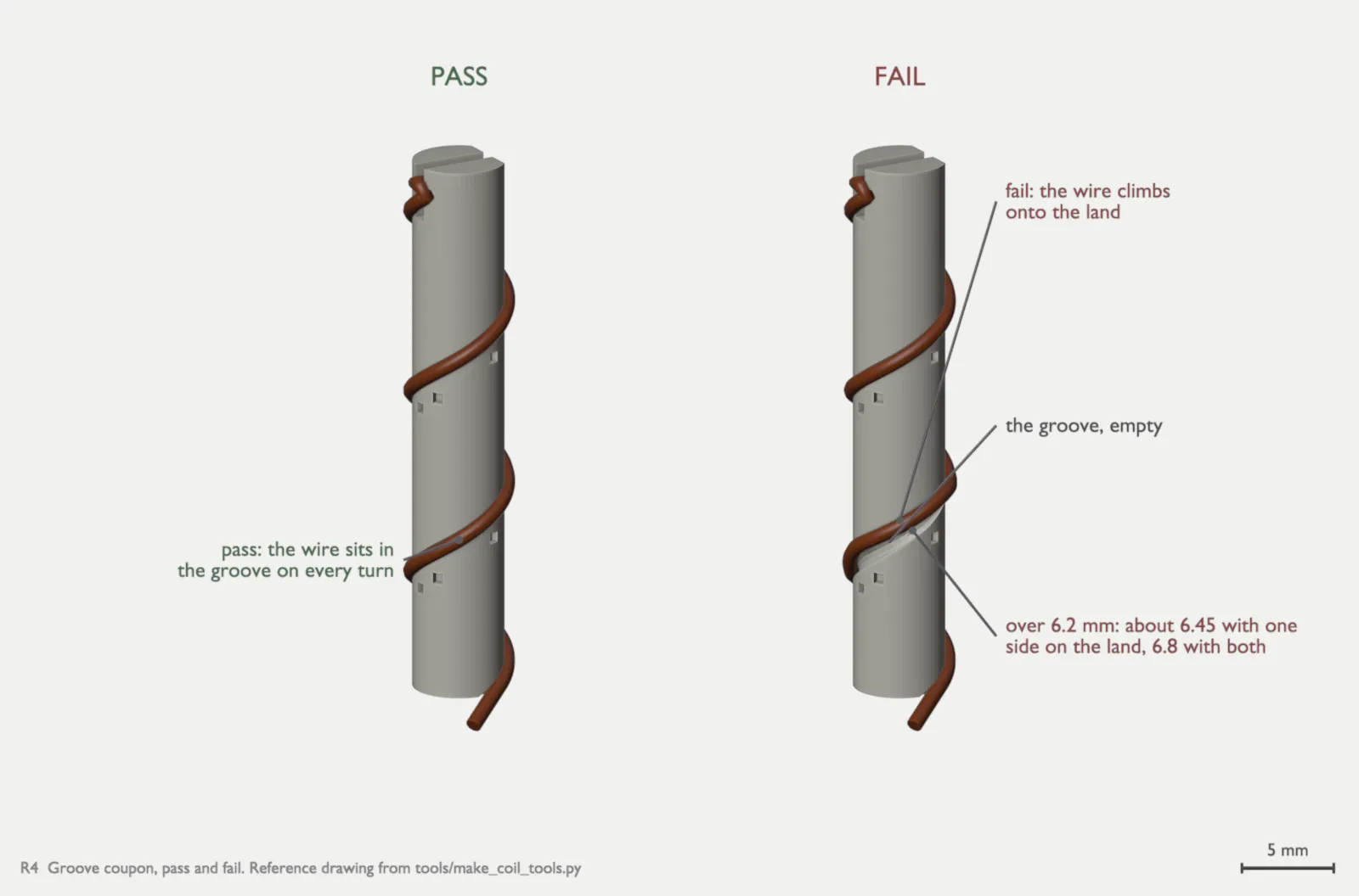
The reference drawings G1 to G5 (the winder) and R3 to R9 are th-blender’s. Bench step 8 of Place the antennas has the short form of this procedure.
Before you start
Section titled “Before you start”| Item | What |
|---|---|
| Bench tools | Coil Winder Mk2: thirteen printed PLA parts, with two Spool Cones, the Base Beam and the Spool Collar (plate pla-Coil Winder Mk2), and its TPU 95A parts: four Feet (and two spares), two Brake Pads and two Brake Pads +0.4 (plate tpu-Coil Winder Mk2 Feet and Brake Pads). ELRS Dipole Gauge (plate pla-Coil Winding Tools; the Mk1 cradle parts on that plate are not used) |
| Winder hardware | Three 4 mm steel rods: two 128 mm (the frame rods) and one 142 mm (the spool rod). If you already have 135 mm rods, cut 7 mm off each frame rod. Four M3 x 16 socket screws (the Base Beam). A brass tube 1.5 mm OD x 1.0 mm ID, 6.5 mm long (the eyelet). Two M3 x 12 socket screws (the hub screws). One M3 x 20 socket screw and an M3 nut (the crank handle’s pin). Optional: one self-adhesive felt pad, 6 x 8 x 1.6 mm, as the fallback brake pad |
| Test print | Antenna Groove Coupons D45 and D55, PETG (plate petg-Antenna Groove Coupons) |
| Wire | 20 AWG enamelled copper wire, 0.85 mm over the enamel (parts list row 16n); 18 AWG bare copper wire, 1.02 mm (row 16m) |
| Tools | Side cutters, callipers, a soldering iron that can strip polyurethane enamel (about 380 °C, ESTIMATE). For the winder: a pin vise with a 1.5 mm drill, a small vise or smooth-jaw pliers, thin CA glue |
1. Assemble the winder
Section titled “1. Assemble the winder”Assemble the winder in this order. Animation G1 shows the seven steps.
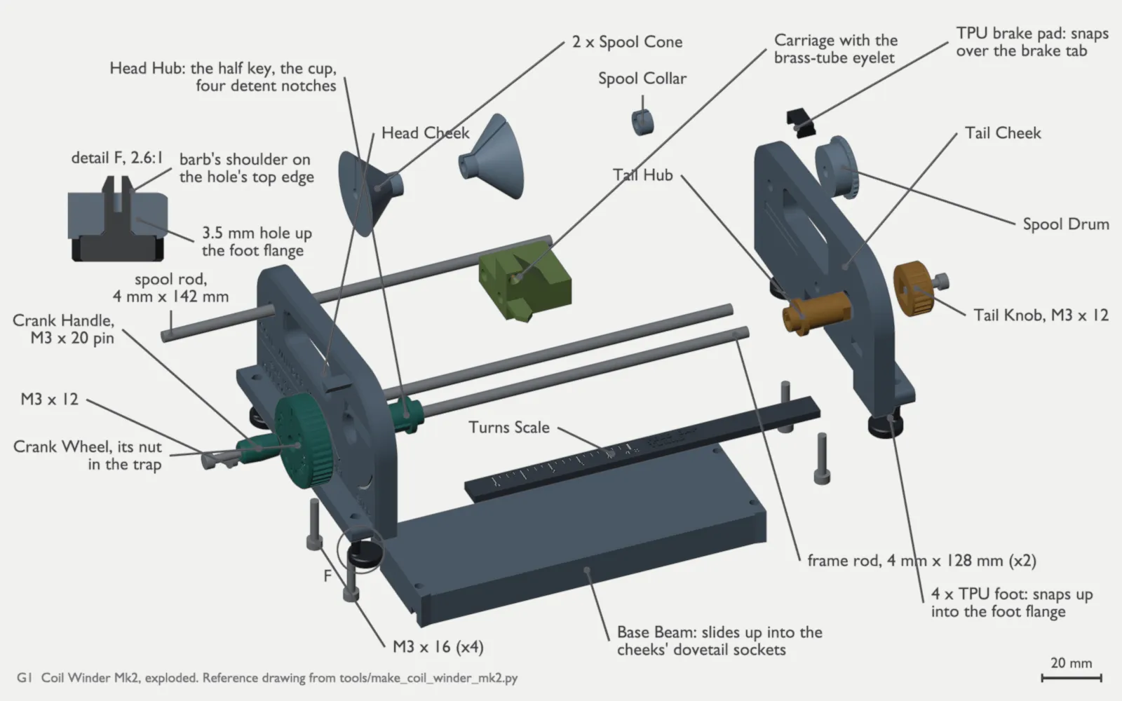
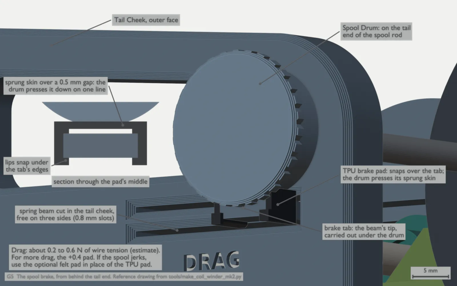
-
Deburr the two ends of the brass tube and make them round. Turn a 1.5 mm drill by hand (in a pin vise) through the hole in the tower of the carriage. Press the tube into the hole with a small vise or smooth-jaw pliers, square to the tower.
CAUTION: Do not crush the tube. The wire must touch only smooth brass.
-
Put the Head Hub into the head cheek from the inner face of the cheek.
-
Push the M3 nut into the nut trap on the inner face of the Crank Wheel. Put the Crank Wheel on the square end of the Head Hub. It goes on in one position only. Attach it with an M3 x 12 hub screw. The screw cuts its own thread in the hub.
-
Put the M3 x 20 screw through the Crank Handle and into the nut in the Crank Wheel. The handle must turn freely on the screw.
-
Press the two 128 mm frame rods into the blind holes in the inner face of the head cheek. Slide the carriage onto the two frame rods.
-
Put the tenon of the Turns Scale into the head cheek.
-
Put the Tail Hub into the tail cheek from the inner face of the cheek. Press the tail cheek onto the frame rods and onto the other tenon of the Turns Scale. Attach the Tail Knob to the Tail Hub with the second M3 x 12 hub screw.
-
Slide the Base Beam up into the dovetail sockets in the undersides of both cheeks, from below. Drive the four M3 x 16 screws up through the beam into the cheeks. The screws cut their own thread.
-
Put the 142 mm spool rod through the head cheek, the two Spool Cones and the spool. Then put it through the Spool Collar and the tail cheek. Push the Spool Collar against the inner face of the tail cheek. Push the TPU Brake Pad onto the brake tab of the tail cheek until its lips click under the tab. The hooks go at the free end of the tab. Push the Spool Drum onto the tail end of the spool rod with a twist. It is a light press fit.
-
Push the four TPU Feet up into the holes in the foot flanges, two under each cheek. Push each foot until its barb clicks out on the top of the flange. To remove a foot, pinch the two halves of the barb together and push it down through the hole.
-
If the eyelet or the Spool Drum turns, attach it with one drop of thin cyanoacrylate (CA) glue. Do not use hot glue.
To change a spool, pull the spool rod out toward the head end. The Spool Collar stays on the spool rod. Push the spool rod back through the new spool. The collar comes back against the inner face of the tail cheek when the spool rod is fully in. The Spool Drum stops the spool rod toward the head end, and the collar stops it toward the tail end.
Do these checks:
- Turn the Crank Wheel. It must click at each quarter turn. At “0” under the pointer, the half key of the Head Hub is upright, below the axis.
- Slide the carriage along the frame rods. It must move freely and stay where you leave it.
- Pull the Tail Knob back. The Tail Hub must slide 4.5 mm back. Push it in again: it has no spring.
- Turn the spool rod slowly. The drag must be light and even, with no jerks. If it jerks, use the felt pad in place of the TPU Brake Pad.
Cheeks printed before 2026-10-12 have no foot holes. Drill a 3.5 mm hole straight through each foot flange, at these positions:
- 3.5 mm out from the outer face of the cheek.
- For the front foot, 7.0 mm from the front end of the flange.
- For the back foot, 8.0 mm from the back end of the flange.
Chamfer the bottom edge of each hole lightly. Keep the top edge sharp: the barb catches on it.
2. Find the groove width
Section titled “2. Find the groove width”Do this before you print the coil formers. The first single-width coupon showed that the groove printed too narrow for
the 20 AWG wire. The Antenna Groove Coupons find the width that holds the wire (plate petg-Antenna Groove Coupons,
th-blender 68bc62c8). Each coupon has bands of 1.5 turns at the pitch of the former (10.31 mm). Each band has its width
engraved.
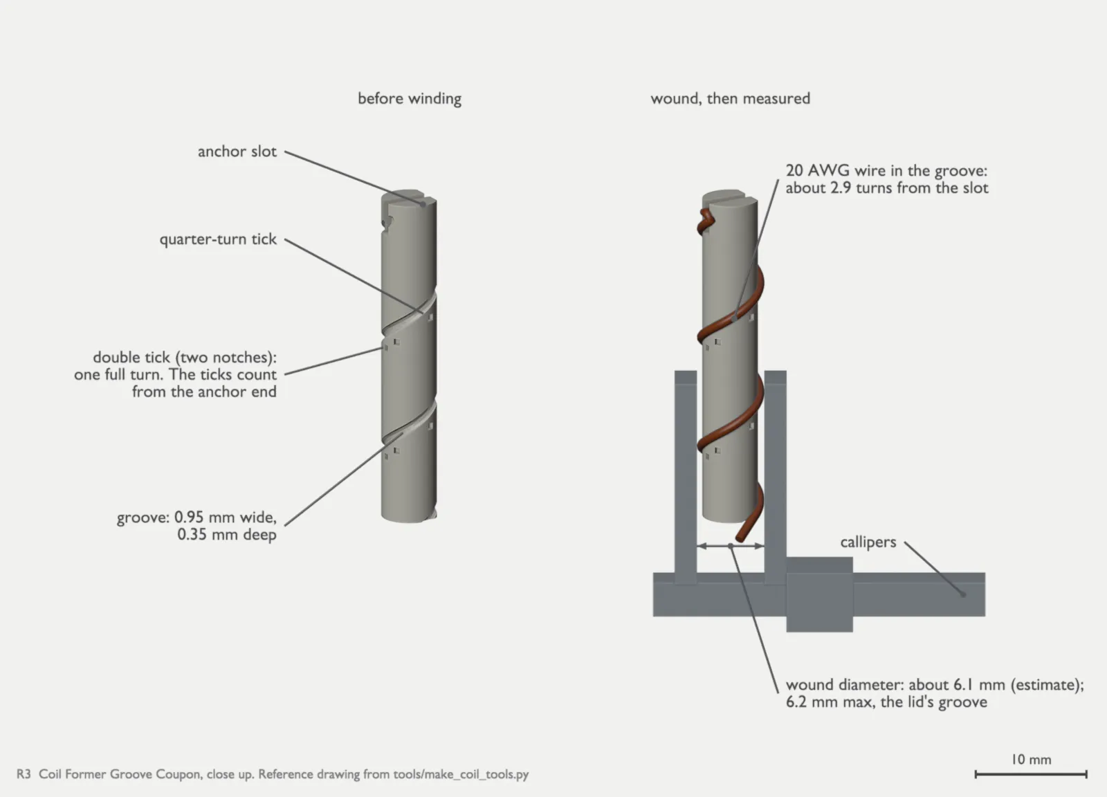
| Coupon | Groove depth | Outside diameter | Band widths |
|---|---|---|---|
| D45 | 0.45 mm | 5.3 mm | 1.00, 1.10, 1.20, 1.30 and 1.40 mm |
| D55 | 0.55 mm | 5.5 mm | 1.10 and 1.20 mm |
- Measure the 20 AWG wire with the callipers. It must be about 0.85 mm over the enamel.
- Print the plate
petg-Antenna Groove Coupons: two coupons, PETG, 0.1 mm layers, about 16 min. - Put the end of the wire in the anchor slot of the D45 coupon. Wind the wire along the full groove. Keep a light, constant tension on the wire.
- In each band, push the wire to the side with a fingernail. A band passes when the wire stays fully in the groove and does not move up onto the land.
- In the narrowest band that passes, measure the wound diameter across the wire at three places. Use the largest value: one reading can find a low point on a turn. It is about 6.1 mm (ESTIMATE). It must be 6.2 mm or less. The coil goes into the 6.2 mm groove of the cassette lid.
- If no band of the D45 coupon passes, do steps 3 to 5 on the D55 coupon.
- Send th-blender the coupon (D45 or D55), the narrowest width that passes and the wound diameter. th-blender sets the formers to that width, and to the 5.5 mm outside diameter if a D55 band passes.
- Print the two LoRa Coil Formers, plate
petg-LoRa Coil Formers (grooved), after th-blender changes them.
The result is the narrowest band that passes. In that band the wire stays fully in the groove under a fingernail push. Its wound diameter is 6.2 mm or less.
Drawings R3 and R4 show the first, single-width coupon. A band of the new coupons passes and fails in the same way.
The coupons are PETG because the formers are PETG. You solder to the formers, and they stay in the keel in the sun. The bench tools are PLA, because they do not fly.
3. Make the ELRS dipole arms
Section titled “3. Make the ELRS dipole arms”Make four arms: two for each dipole, and one dipole for each keel.
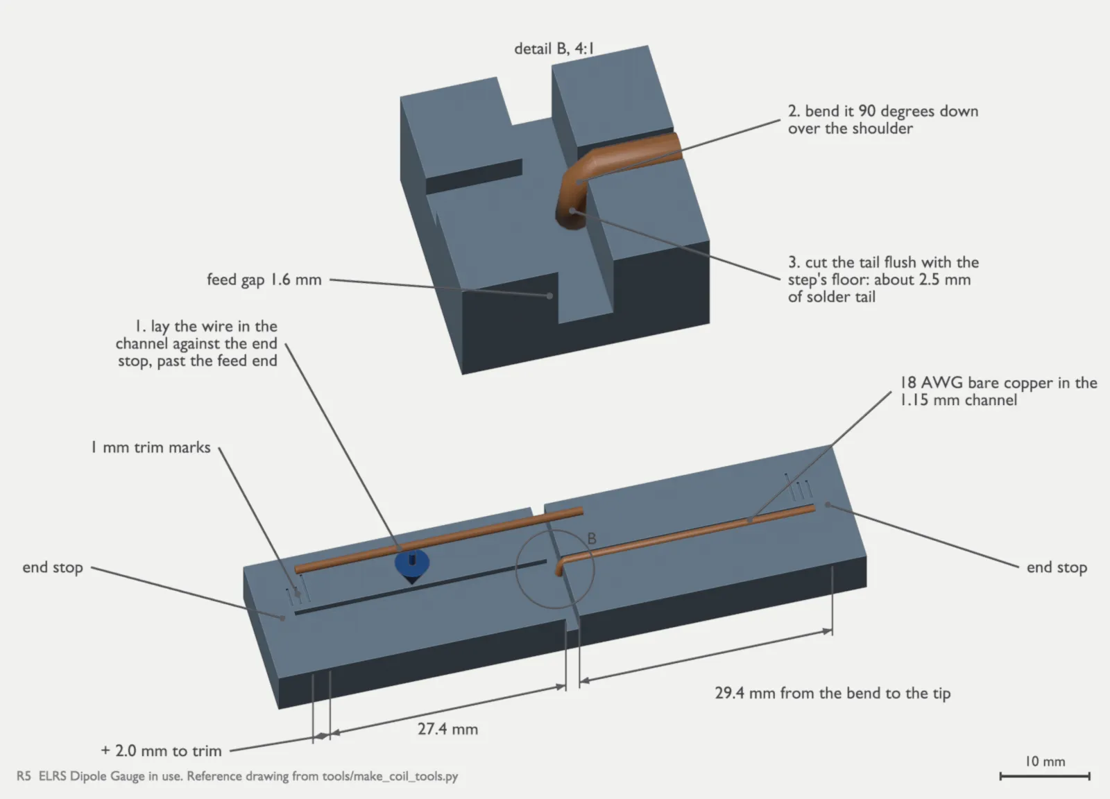
- Put the 18 AWG wire in a channel of the dipole gauge, against the end stop. Let it go past the feed end.
- Bend the wire 90 degrees down over the shoulder. Its end rides over the far edge of the step.
- Cut the tail flush with the floor of the step. This gives a solder tail of about 2.5 mm. The exact length of the tail is not important, because the tuning in step 7 corrects it.
- Make sure that the arm is 29.4 mm long from the bend to the tip. That is 27.4 mm, plus 2.0 mm that you trim in step 7. The solder tail is extra.
4. Wind the LoRa coils
Section titled “4. Wind the LoRa coils”Formers printed before 2026-10-12 (before th-blender’s 48030b7) have a 1.2 mm feed hole. Open it to 1.8 mm with a pin vise before you wind. Their double ticks print as one wide notch; that does not change the turns.
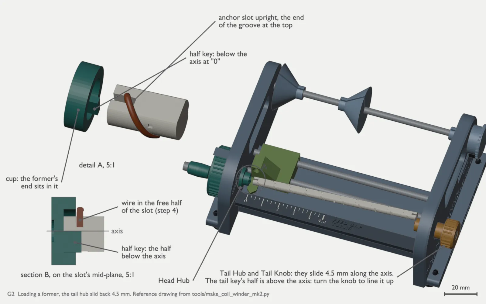
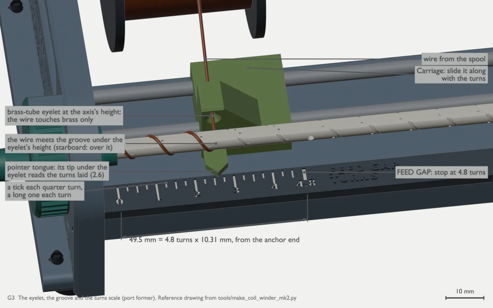
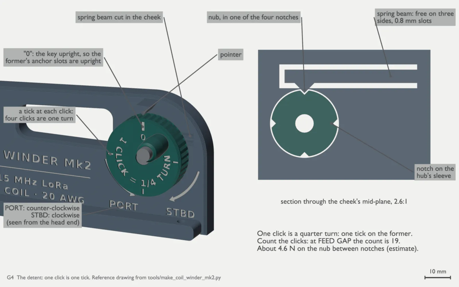
Use the port former for the port keel and the starboard former for the starboard keel. The turns go in opposite directions: the port former has a right-hand helix, and the starboard former a left-hand helix.
Turn the Crank Wheel in the direction moulded on the head cheek. PORT is counter-clockwise and STBD is clockwise, seen from the head end.
- Turn the Crank Wheel to “0”. The half key of the Head Hub is then upright, below the axis.
- Pull the Tail Knob back 4.5 mm. Turn the former until an anchor slot is upright. The end of the groove must be at the top of the slot. Put the slot on the key. The key goes into the half of the slot below the axis. Put the end of the former in the cup. Lay the former on the axis. Turn the Tail Knob until the key of the Tail Hub is upright, above the axis. Push the Tail Knob back in. The key of the Tail Hub goes into the half of the other anchor slot above the axis.
- Make sure that the wire spool is on the spool rod between the two Spool Cones (step 1). Feed the wire through the brass eyelet of the carriage.
- Bend the last 1.5 mm of the wire 90 degrees. Put the bent end down the free half of the anchor slot at the head end, above the key. The bend must sit at the mouth of the slot. The bend holds the end of the wire when you pull the wire tight. The wire goes from the slot into the groove. Slide the carriage until its pointer is at 0 on the Turns Scale.
- Turn the Crank Wheel. Keep the wire in the groove. Slide the carriage with the turns, so that the eyelet stays over the turn that you lay.
- Count the clicks from the anchor slot. Turn the Crank Wheel until the pointer is at FEED GAP on the Turns Scale. This is 19 clicks, then a short turn past the 19th click (about a fifth of a click). Stop at the feed gap. Do not wind into it. The arm is then 4.8 turns, 49.5 mm.
- Make sure that the count at the feed gap is 19. If it is not 19, the wire skipped a turn or climbed onto the land. Unwind the arm and wind it again.
- Tin the last 5 mm of the end of the first arm. Put it through the 1.8 mm feed hole. This holds the turns in the groove.
- Pull the Tail Knob back and remove the former. Turn the Crank Wheel to “0”. Turn the former end for end. Put it back with the other anchor slot on the key of the Head Hub. The end of the second arm’s empty groove must be at the top of the head slot (step 2). The end of the first arm is then in the half of the tail slot below the axis. Turn the Tail Knob until the key of the Tail Hub is above the axis. Push the Tail Knob back in. The key must not touch the end of the first arm.
- Wind the second arm in the same way. Bend the last 1.5 mm of the wire, as in step 4. Put the bent end in the free half of the anchor slot. Wind from the anchor slot to FEED GAP: 19 clicks.
CAUTION: Each hub key fills only half of the anchor slot. The end of the wire goes in the other half. If the key of the Tail Hub does not go in, do not push it: it crushes the wire. Make sure that the end of the groove at the head end is at the top (step 2). The end of the first arm is then below the axis at the tail. The key goes in above it.
If the wire is loose on the spool, use the Brake Pad +0.4.
CAUTION: Do not wind the wire across the feed gap. Each arm stops at the gap.
5. Make the feed joints
Section titled “5. Make the feed joints”The PETG former softens at about 80 °C (ESTIMATE), and the iron is at about 380 °C. Make each joint quickly.
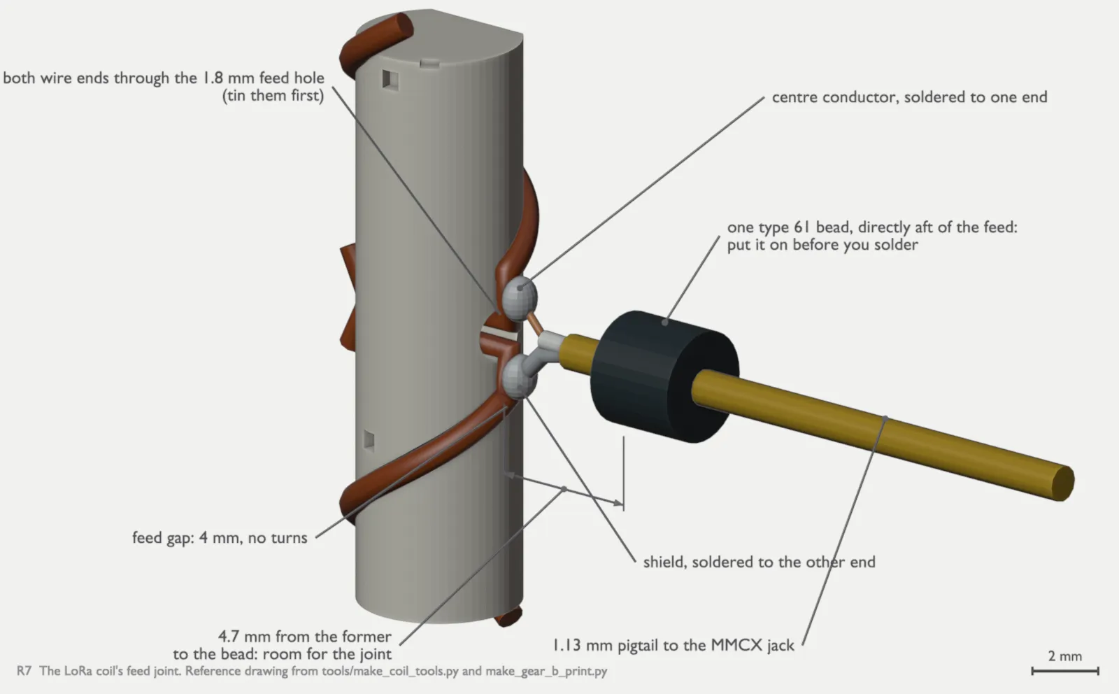
- Put the beads on the pigtails before you solder. Put one type 61 bead (Fair-Rite 2661000101) on each LoRa pigtail and five on each ELRS pigtail. The other end of each pigtail has its MMCX jack, so the beads go on only from the feed end.
- Tin the end of the second arm before it goes through the feed hole. The enamel melts when you solder.
- Make sure that both wire ends are through the feed hole.
- Solder one wire end to the centre conductor of the LoRa pigtail and the other end to the shield. Use flux.
- Push the LoRa bead aft until it touches the end of its pocket in the cassette lid. This leaves about 4.7 mm between the feed hole and the bead for the joint.
- Solder one ELRS dipole arm to the centre conductor. Solder the other arm to the shield, across the 1.6 mm feed gap.
6. Install the cassette
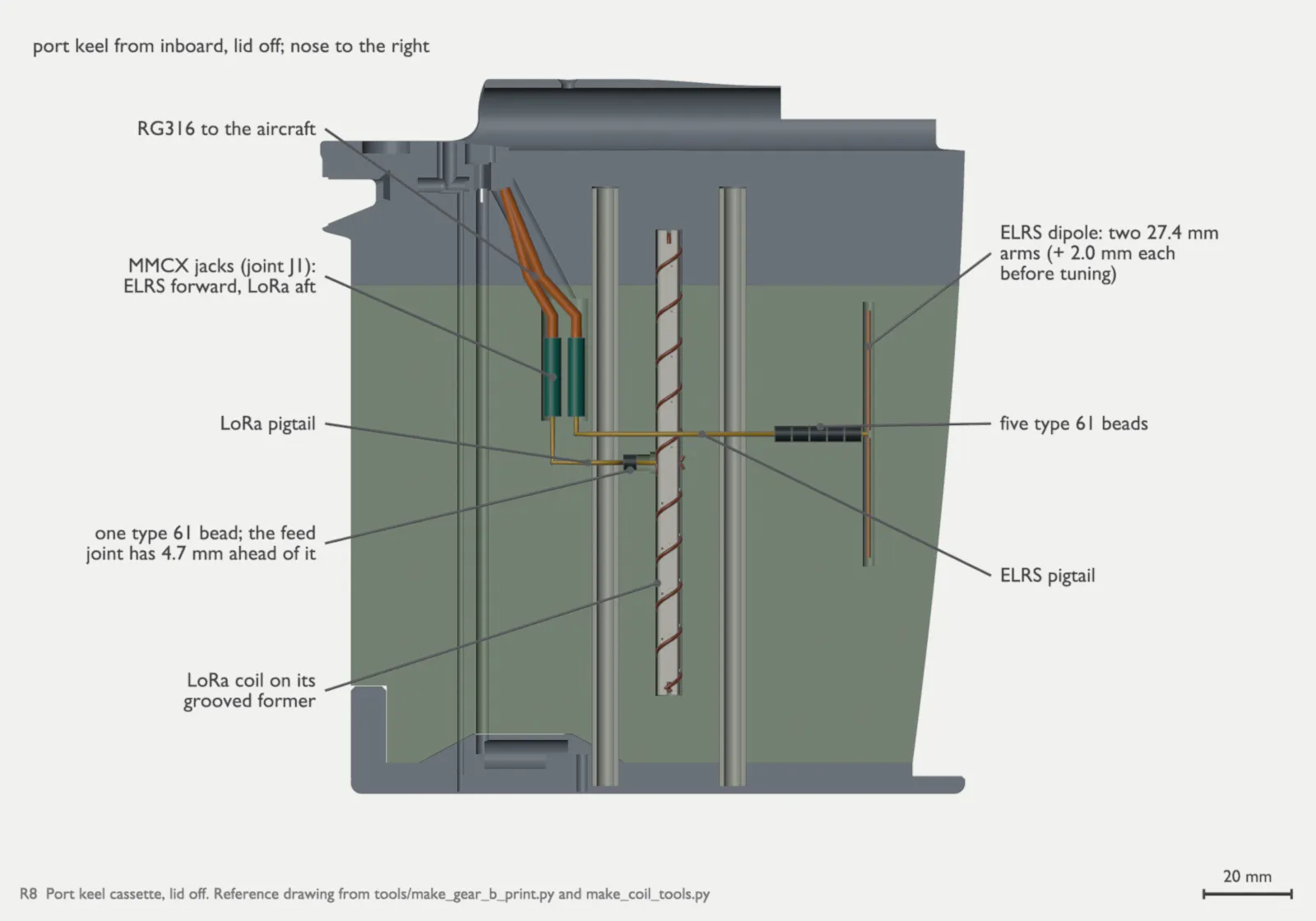
Section titled “6. Install the cassette”- Put the dipole, the coil, the pigtails and the beads in the cassette lid.
- Connect the pigtails to the MMCX jacks (joint J1).
- Install the two strobe LEDs and the lighting charge lead with its bead in the keel before you tune. They are near the coil (since 2026-10-11).
- Attach the lid to the keel with four M2 countersunk screws: three M2 x 6 and one M2 x 5. Use brass or nylon screws.
CAUTION: Do not use steel screws, tape or glue near an antenna element. They change the tuning.
7. Tune the antennas
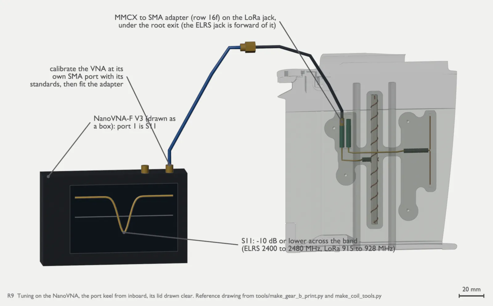
Section titled “7. Tune the antennas”- Calibrate the NanoVNA-F V3 at its own SMA port, with its calibration standards. There are no MMCX standards.
- Install the MMCX to SMA adapter (row 16f). A short adapter moves the phase, not the frequency of the lowest S11.
- Connect the adapter to the MMCX jack under the keel root exit.
- Tune the ELRS dipole. Cut the same length from the tip of each arm, with the 1 mm marks of the gauge. A 1 mm cut from both arms raises the frequency by about 80 MHz (ESTIMATE). The first measurement is at about 2280 MHz (ESTIMATE). Near the target, cut 0.5 mm from each arm at a time. Measure after each cut.
- Make sure that the S11 of the dipole is -10 dB or lower across 2400 to 2480 MHz.
- Tune the LoRa coil. Unwind one tick (a quarter turn) at the anchor end of each arm, the same on both arms. One tick on both arms raises the frequency by about 45 to 50 MHz (NEC2, simulated). For the last step, unwind half a tick (an eighth of a turn) on each arm. The ticks count from each anchor end, so the feed joint does not move. After each trim, cut the unwound wire off at the tick, where it leaves the groove.
CAUTION: Do not leave the unwound wire standing off the former. It is still part of the antenna. The 6.2 mm groove of the lid holds the turns in place. 7. Make sure that the S11 of the coil is -10 dB or lower across 915 to 928 MHz. Make sure that the lowest S11 is between 910 and 935 MHz. 8. Record the results for each element in the table below.
CAUTION: Do not tune the coil without the pigtail and the beads installed. The pigtail lowers the resonance of the coil by 10 to 28 MHz (NEC2, simulated).
| Keel | Element | Frequency of lowest S11 (MHz) | Lowest S11 (dB) | S11 at the band edges (dB): 2400 and 2480, or 915 and 928 | Date |
|---|---|---|---|---|---|
| Port | ELRS dipole | ||||
| Port | LoRa coil | ||||
| Starboard | ELRS dipole | ||||
| Starboard | LoRa coil |
Source: docs/make-keel-antennas.md in the repo. Edit it there; this page is generated.
Comments
Comment on the whole page here, or on one section or step with the button beside it.