
Build the airspeed tube
This procedure makes the airspeed tube from brass tube. The tube supplies total pressure only. The two static ports in the Fuselage Front supply static pressure. To install the tube, refer to the build path, step 7, the nose package (N1 and N2). To test the installed tube, refer to the first-flight card, step 21. Airspeed tube nose gives the reasons for the shape of the tube.
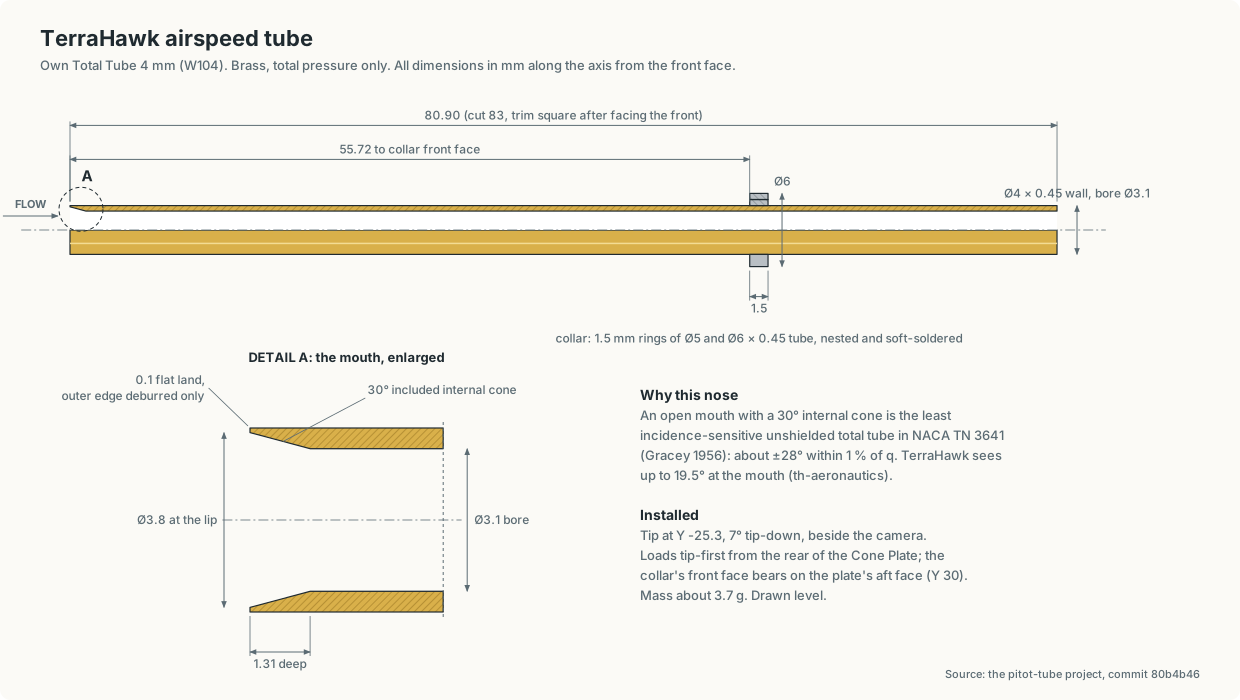
The tube is 80.90 mm long and 4 mm in diameter, with an open front end and a collar. Its mass is 3.63 g.
Before you start
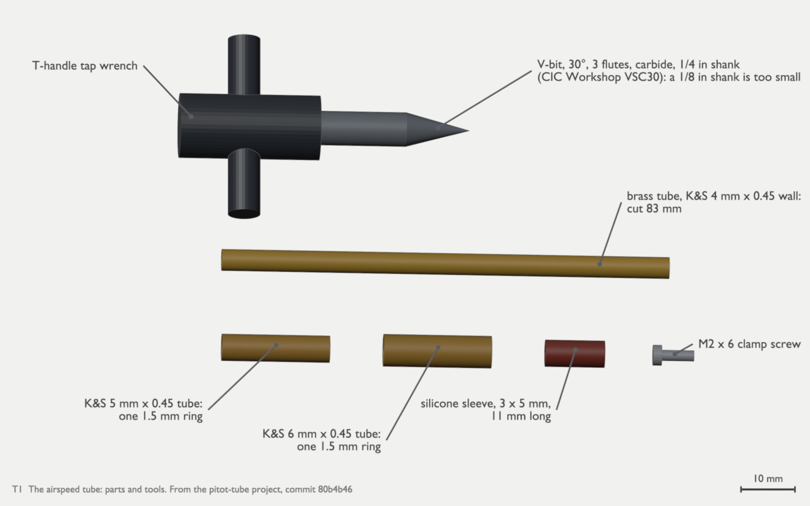
Section titled “Before you start”- Get the parts and the tools in the tables.
- Read the drawing. All dimensions are in millimetres along the axis from the front face.
| Part | Quantity | Source |
|---|---|---|
| K&S brass tube, 4 mm x 0.45 mm wall | 83 mm | Parts list, row 11g |
| K&S brass tube, 5 mm x 0.45 mm wall | One ring, 1.5 mm | Parts list, row 11l |
| K&S brass tube, 6 mm x 0.45 mm wall | One ring, 1.5 mm | Parts list, row 11m |
| Soft solder and flux | As necessary | Shop stock |
| Tool | Note |
|---|---|
| Wheel tube cutter | Cuts the ends square |
| V-bit, 30°, 3 flutes, carbide, 1/4 in shank (CIC Workshop VSC30) | Parts list, bench tools |
| T-handle tap wrench | Holds the 1/4 in shank |
| Vise with soft jaws | Holds the tube |
| Calipers | Measure the length and the collar position |
| Magnifier | Lets you see the 0.1 mm land |
| Fine file, 400 and 1000 grit abrasive paper | Remove the burrs |
| Soldering iron | |
| Isopropyl alcohol | Removes the flux |
Stage 1: Cut the tube
Section titled “Stage 1: Cut the tube”- Cut 83 mm of the 4 mm tube with the tube cutter.
- Tighten the wheel a small quantity at each turn. Do not crush the tube.
Check: The front end is square to the axis. The tube is round at the cut.
Stage 2: Cut the internal cone
Section titled “Stage 2: Cut the internal cone”- Put the V-bit in the tap wrench.
- Hold the tube in the vise with soft jaws. Let 10 mm of the front end extend.
- Put the tip of the bit into the front end.
- Turn the bit clockwise with light pressure. The bit centres itself in the bore.
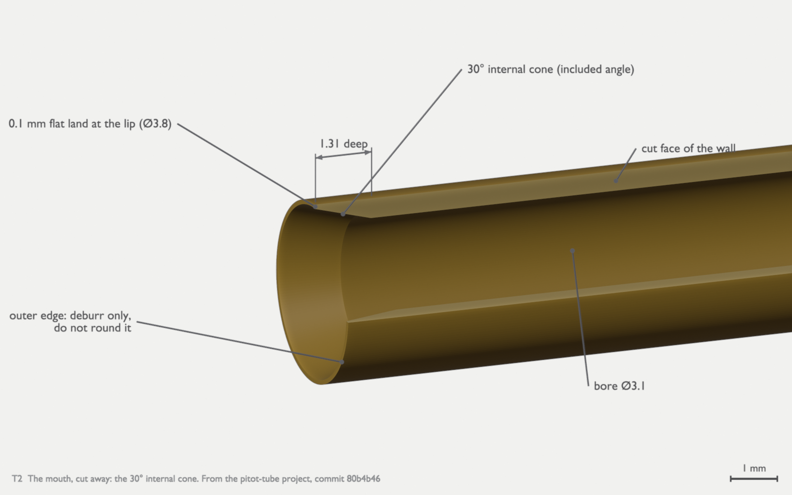
- Stop when a flat land of 0.1 mm remains at the lip. Use the magnifier to see the land.
- Remove the bit.
- Remove the burr from the outer edge with 1000 grit abrasive paper. Do not make the edge round.
Check: The land is even around the full lip. The outer edge is sharp, not round. The cone goes 1.31 mm into the bore.
Stage 3: Cut the tube to length
Section titled “Stage 3: Cut the tube to length”- Measure 80.90 mm from the front face. Make a mark.
- Cut at the mark with the tube cutter.
- Remove the burr from the bore at the aft end with the fine file.
Check: The length is 80.90 mm ±0.3 mm. The aft end is square.
Stage 4: Install the collar
Section titled “Stage 4: Install the collar”- Cut a ring of 1.5 mm from the 5 mm tube with the tube cutter.
- Cut a ring of 1.5 mm from the 6 mm tube.
- Remove the burrs from the two rings.
- Clean the tube at the collar position with 400 grit abrasive paper and isopropyl alcohol.
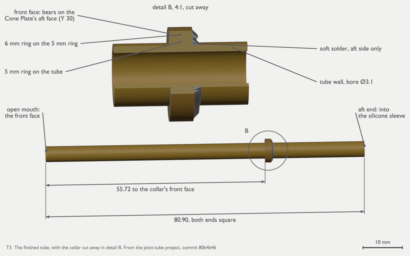
- Slide the 5 mm ring onto the tube from the aft end.
- Slide the 6 mm ring onto the 5 mm ring.
- Put the front face of the collar 55.72 mm from the front face of the tube.
- Apply flux to the aft side of the collar.
- Solder the aft side of the two rings to the tube.
- Remove the flux with isopropyl alcohol.
Check: The front face of the collar is 55.72 mm ±0.2 mm from the front face of the tube. The front face of the collar is clean and square. The collar does not move.
Stage 5: Do a check of the tube
Section titled “Stage 5: Do a check of the tube”- Look through the bore at a light.
- Blow through the tube.
Check: The bore is clear. Air flows freely through the tube.
The tube has no joint in its wall, so the tube itself cannot leak. The leak check is part of the bench check after you install the tube.
Install and test the tube
Section titled “Install and test the tube”- Install the tube. Refer to the build path, step 7, the nose package: put the tube in tip first from the rear of the Cone Plate, seat the collar in the plate’s aft pocket, and put in the M2 x 6 clamp screw.
- Do the bench check. Refer to the first-flight card, step 21.
Sources
Section titled “Sources”The dimensions, the build order and the tolerances come from the pitot-tube project (commit 171d465; the figures cite 80b4b46, with the same dimensions). The tube’s mass and the installed position come from th-blender’s W104 promotion (888383ba), and the collar’s job and the sleeve’s grip from th-blender’s W102 fit pass. The parts and the V-bit are in the parts list (th-main a6f9b0b0). The ±0.3 mm length tolerance, the 10 mm of tube out of the vise and the statement that the tube cannot leak are pitot-tube’s reasoning, not measurements. The figures are from the pitot-tube project (commit 30baf7d).
Comments
Comment on the whole page here, or on one section or step with the button beside it.