
Test prints
Each test print checks one setting or one fit before the airframe parts print. The slicer settings are the real ones: each test loads the same files as the print jobs, then changes only what the test needs. A test with bands changes one value with height, for example the nozzle temperature. The bands go into the G-code, and the slicing script reads the G-code back to make sure that each band starts at its height. Record the results in the tuning log.
Machine baseline
Before any material test: first layer and mesh, extruder, squareness and Z.
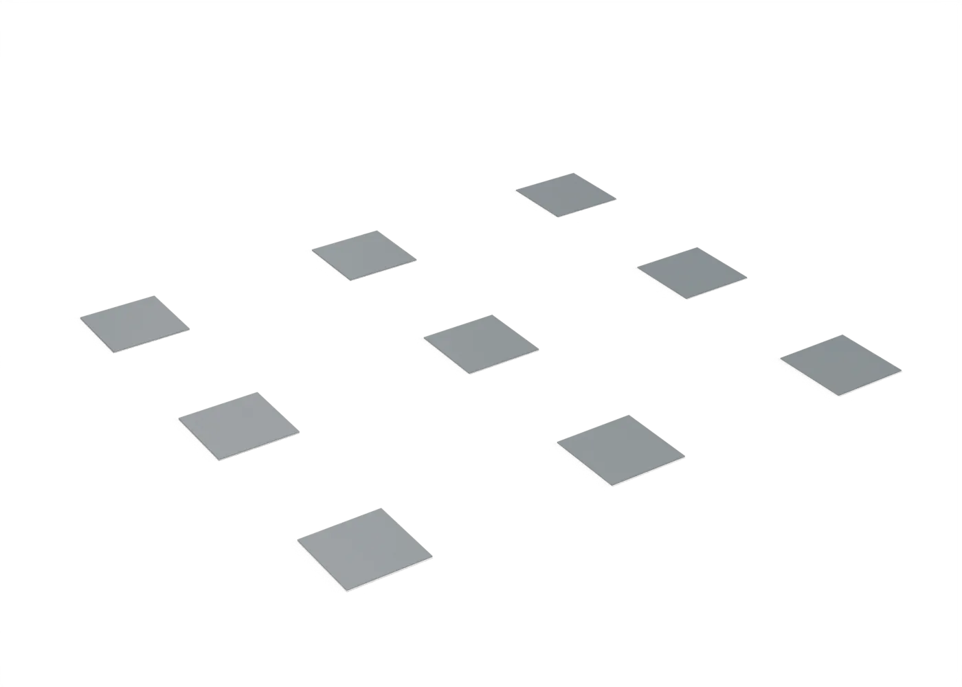
- First layer and meshNine two-layer squares over the whole bed: first-layer height and mesh, corner to corner.
- no printExtruder calibrationHeat, then push exactly 100 mm of filament slowly: the rest of the marked 120 mm tells the true steps.
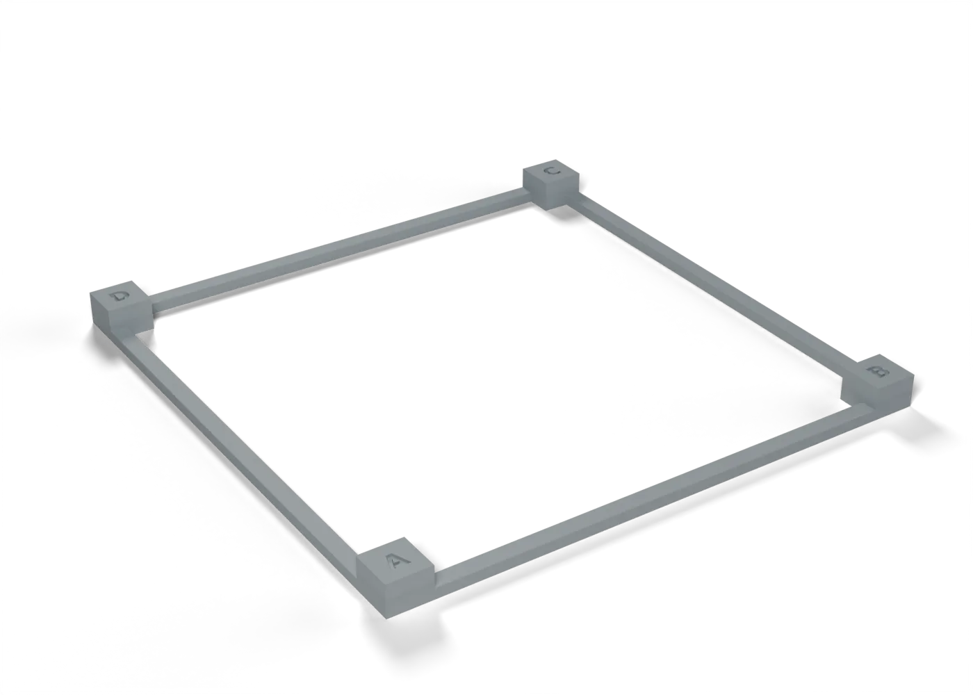
- XY squarenessA 100 mm frame on four posts: the two diagonals give the skew, the sides give the XY scale.
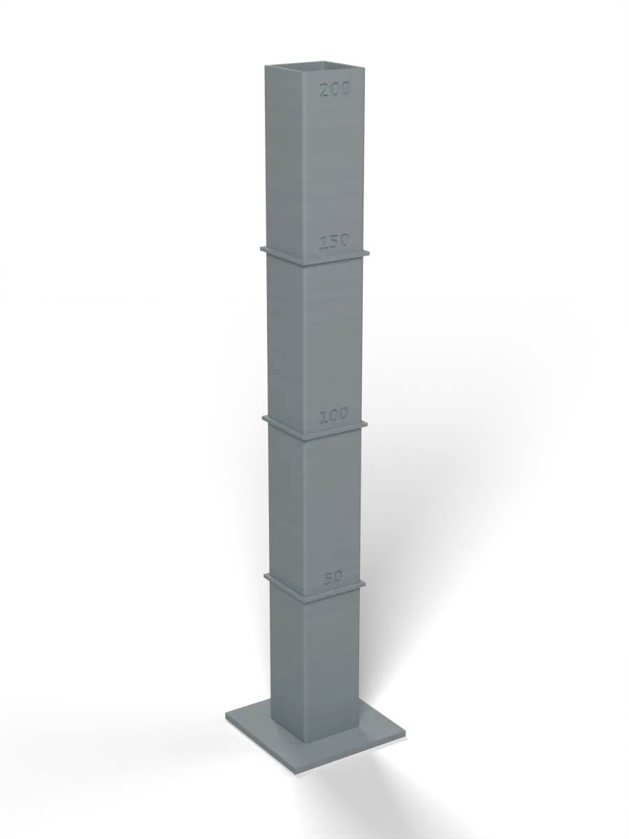
- Z accuracy at 200 mmA 200 mm tube with ledges every 50 mm: the heights show the Z steps, the walls show wobble.
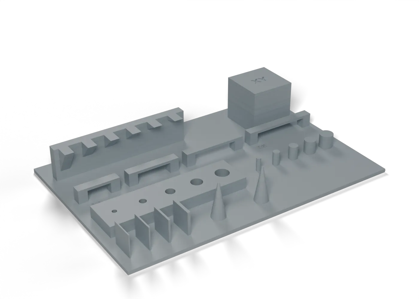
- Multi-testThe usual all-in-one plate: overhangs, bridges, holes, pins, thin walls, stringing and XY scale.
LW-PLA: the foam is the calibration
Foaming depends on temperature and time in the melt zone, so run these on each printer.
- LW-PLA expansion mapA single-wall coupon at 35 mm/s, 250 down to 200 °C in 10 mm bands: measure and weigh each band.
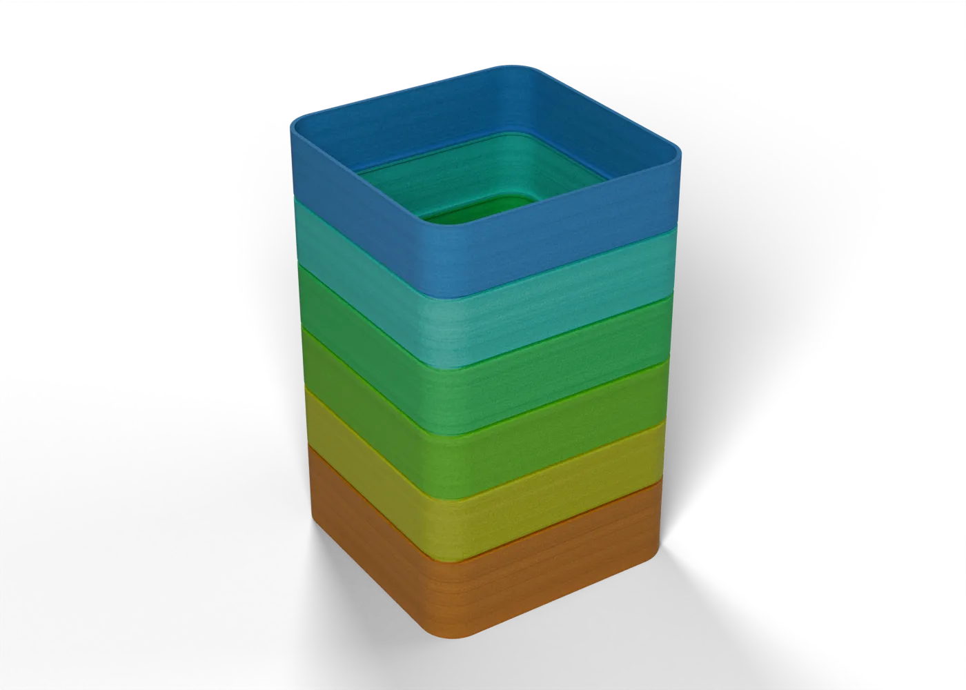 6 bands
- LW-PLA speed sensitivityThe same coupon at 15, 25 and 35 mm/s: does slower foam more, and by how much?
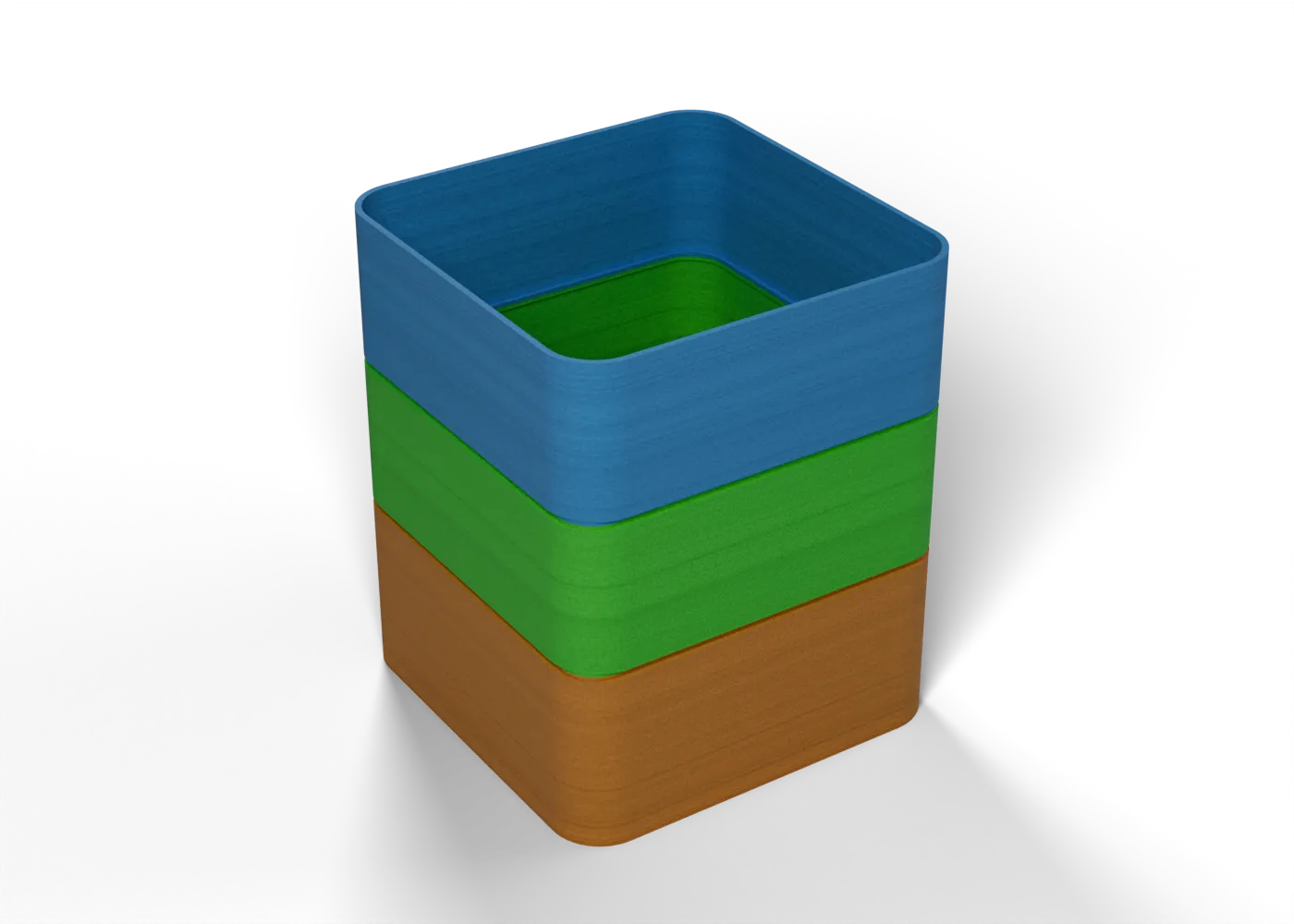 3 bands
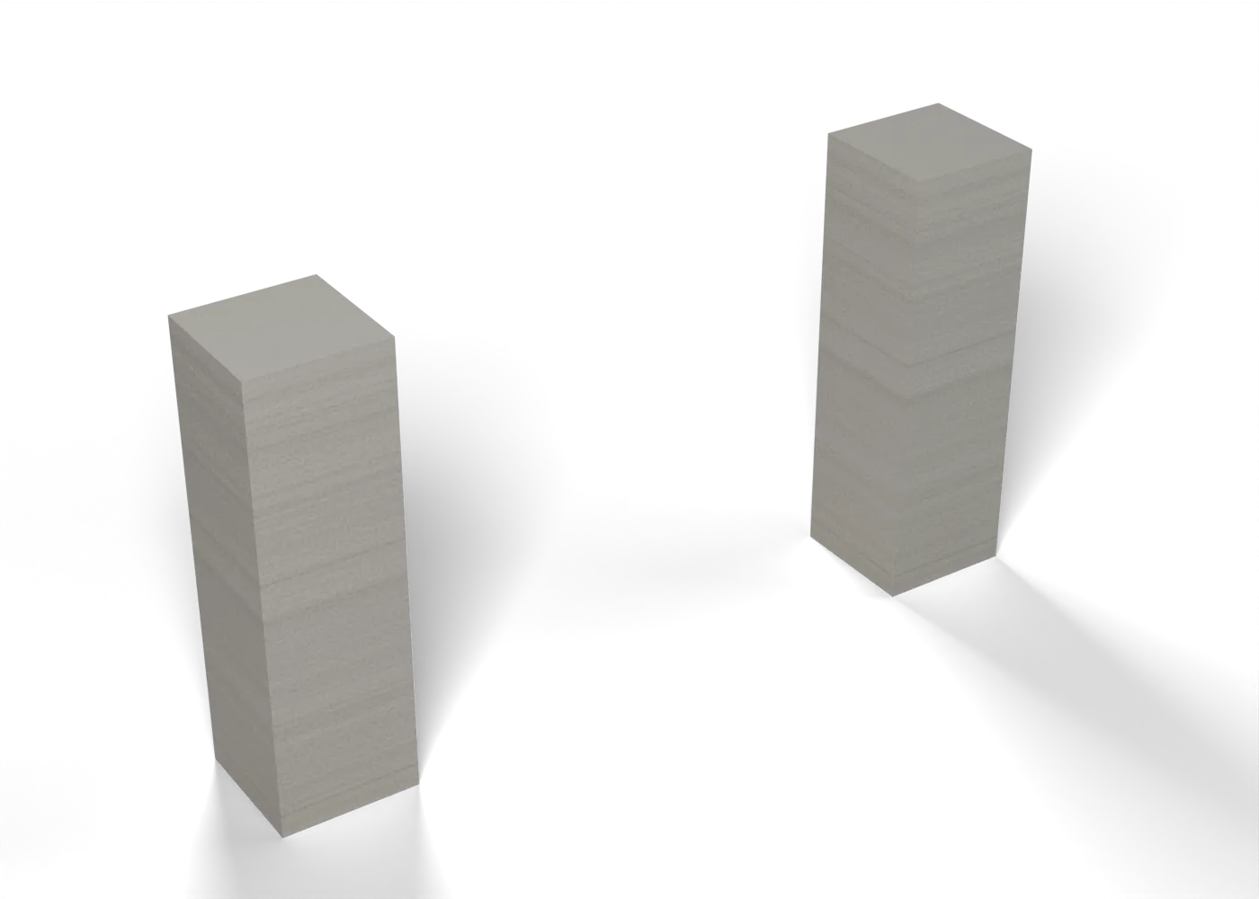
- LW-PLA travel and oozeTwo towers with avoid-crossing-perimeters on: strings across the gap show travel and wipe, not retraction.
- Airfoil slice20 mm of the real Wing Outer: one perimeter, a closed trailing edge, infill bonded, the bore on the tube.
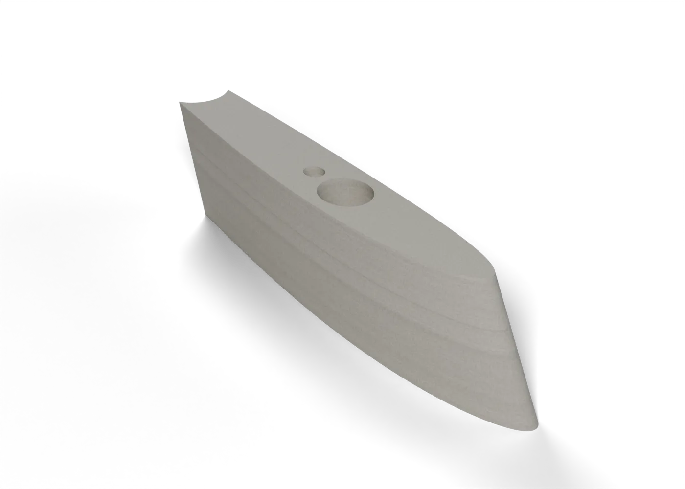
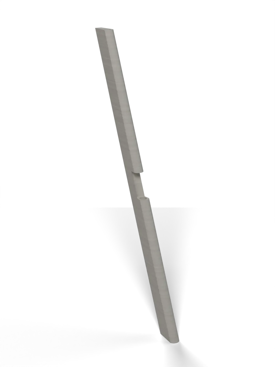
- Elevon strip, full heightThe elevon's leading edge with its spar bore, full height on the Kobra Max: the riskiest print, for a few grams.
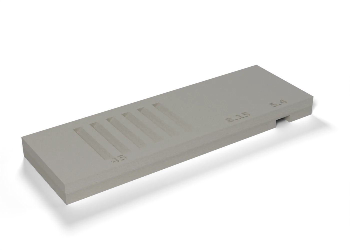
- LW-PLA overhang and bridgeThe 45° louvre slots, the 8.15 mm pocket ceiling and the 5.4 mm bridge, at 100 % fan and at 30 %.
- print jobMass gate: the wing tipThe Wing Tip A test print within 5 % of its sliced mass, before any large LW-PLA part.
PETG: strength and fits
The stock PETG settings are tuned for looks, not load paths.
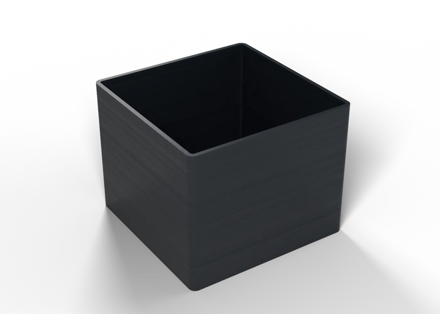
- PETG flowA single-wall cube: its wall should measure one extrusion width.
- PETG pressure advanceSix 6 mm bands of pressure advance, 0 to 0.08: pick the sharpest corners. The tower is small, so its walls print at about 26 mm/s.
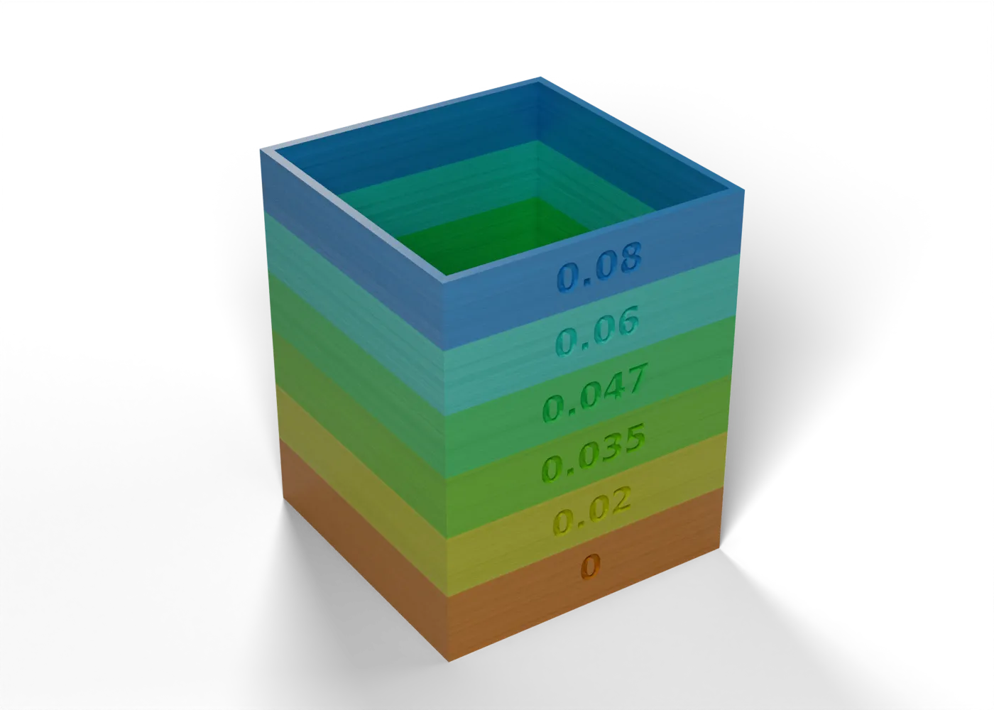 6 bands
- PETG temperature tower255 down to 225 °C in 8 mm bands: bridge, 45° overhang and strings at each.
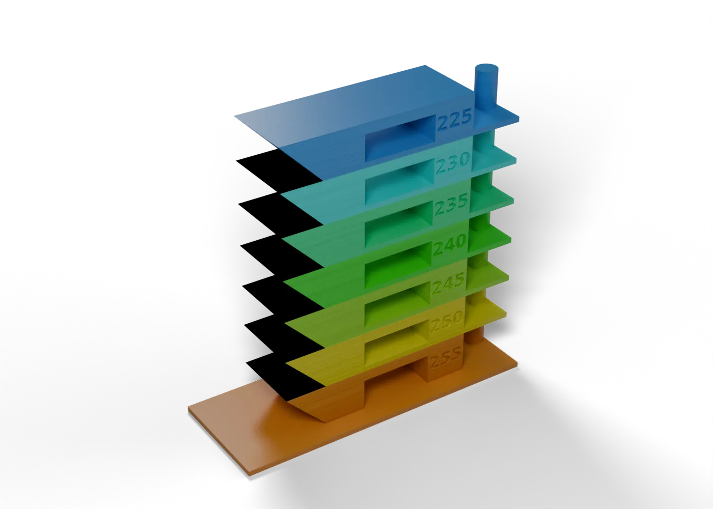 7 bands
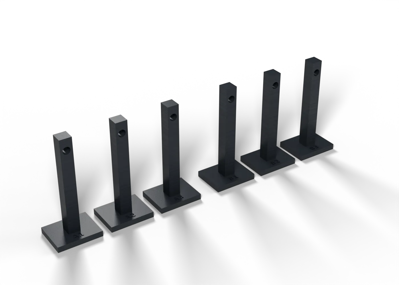
- PETG layer adhesionUpright bars at stock settings and with walls at 40 mm/s and 30 % fan, broken between layers.
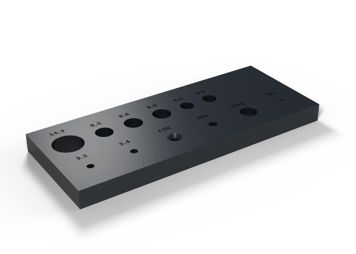
- Fit gaugeSpar bores, M3 clearance and countersink, insert hole, magnet pocket and M2 pilot on one plate.
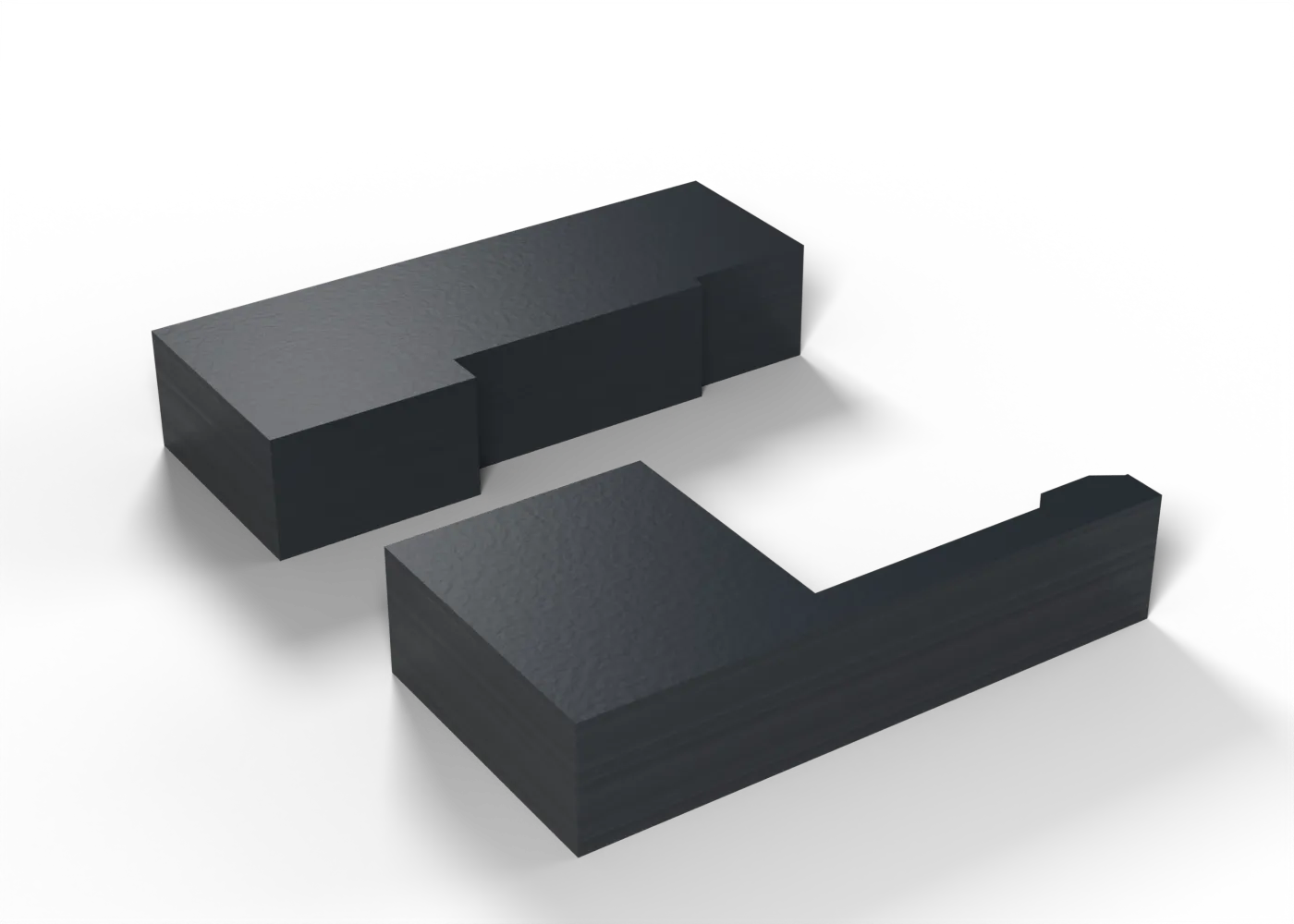
- Snap fatigueOne snap arm and its keeper: click it 50 times, then look for whitening and cracks at the root.
- PETG-to-LW bond15 mm lap joints, one in CA and one in epoxy, pulled to failure. The Dowel Coupon tests fit, not bond.
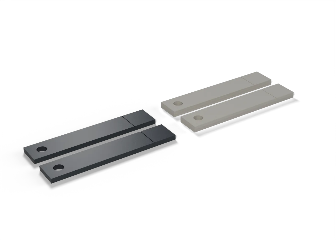
- Wing clipOur wing clip on a base with 1.0, 1.2 and 1.4 mm catches: does it snap, hold 25 N and release by fingernail?
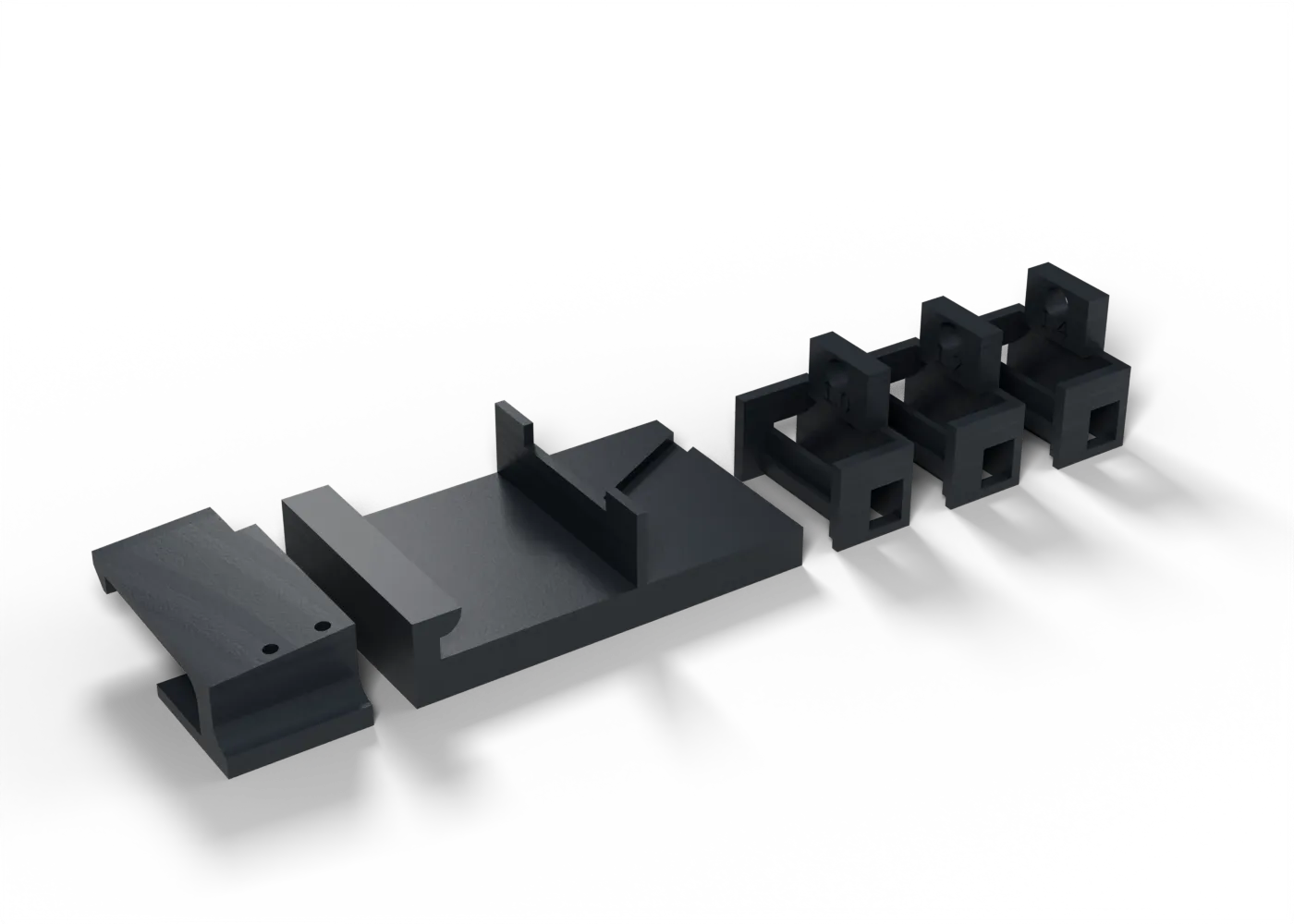
- Heat creepA loaded cantilever at 60 °C: the PETG result is the yardstick for GF-PLA.
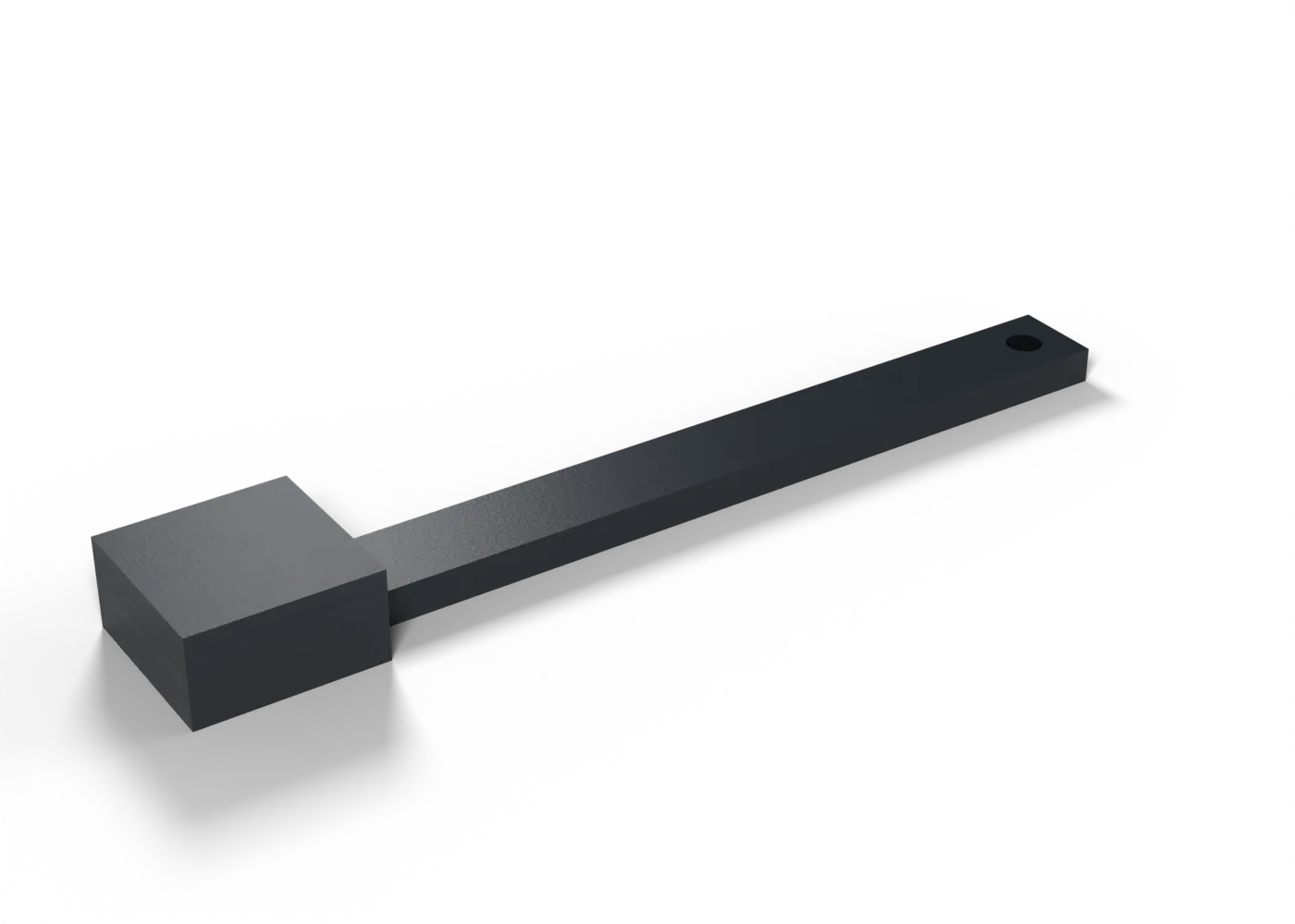
GF-PLA: check before adopting
Nozzle first. Then flow, Z strength, fits and heat.
Comments
Comment on the whole page here, or on one section or step with the button beside it.