
Z accuracy at 200 mm
Test prints / Machine baseline
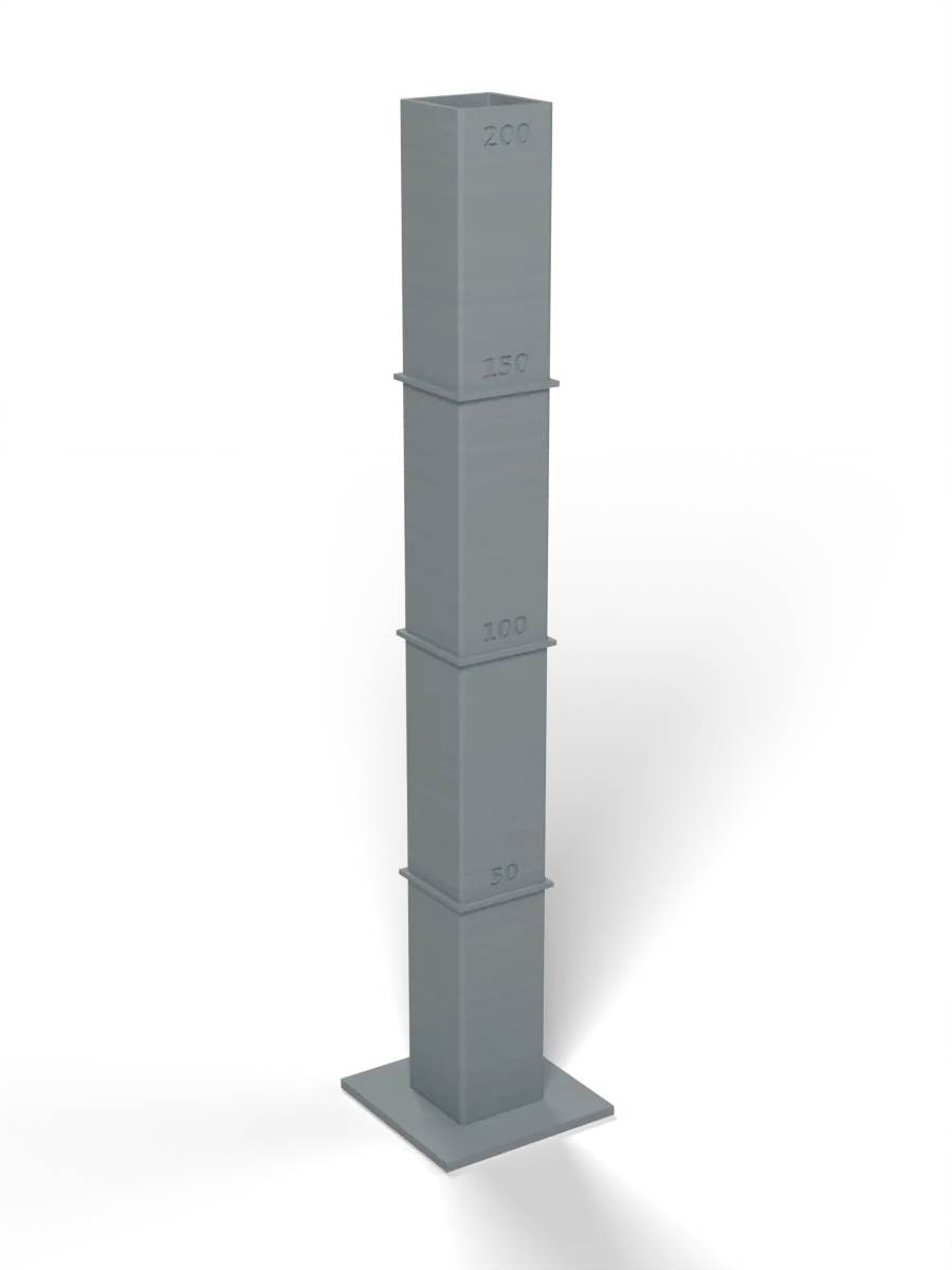
A 200 mm tube with ledges every 50 mm: the heights show the Z steps, the walls show wobble.
Toolpaths
Every extrusion move in the G-code, layer by layer. Drag the layer slider, scrub through the top layer, or play the print.
Toolpaths load when you open this view.
Read from the G-code that the printer gets. The clock adds each move at its programmed speed, without acceleration or travel, so it is shorter than the slicer's estimate.
Settings
On top of the stack that the print jobs load. The printer tuning page shows that stack.
| Printer | File | Changes |
|---|---|---|
| Prusa Core One+ | z-tower (core-one-plus).bgcode | perimeters 2fill_density 0%bottom_solid_layers 10 |
| Anycubic Kobra Max | z-tower (kobra-max).gcode | perimeters 2fill_density 0%bottom_solid_layers 10 |
| Original Prusa i3 MK2 | z-tower (prusa-i3-mk2).gcode | perimeters 2fill_density 0%bottom_solid_layers 10 |
Procedure
What it is for. It shows that the Z axis moves the correct distance over the full height, with no wobble and no skipped steps. A Z error changes the height of every tall part.
Print. Print in plain PLA. Use the file sliced on 2026-10-11 or later. The earlier file left the foot hollow under the tube, so the tube broke off the foot.
Measure. The nominal height is engraved just above each ledge, and 200 under the rim. Measure the ledges at 50, 100 and 150 mm from the bed face of the foot, with a height gauge or calipers. Measure the top at 200 mm with a height gauge. If you have no height gauge, measure from the 150 mm ledge to the top with the calipers’ depth gauge, and add the 150 mm reading. A steel rule is not accurate enough. Look at the walls against a light.
Pass. Each height is within 0.2 mm. Regular ripples mean Z wobble; single steps mean a slip.
Record. The four heights, and the height of any ripples or steps.
In the tuning log
- Z steps at 200 mmTo test
Comments
Comment on the whole page here, or on one section or step with the button beside it.