
Electronics Notes
These notes are about candidate parts. Each part is compared with the manufacturer’s recommended electronics list.
Flight controller, revisited 2026-09-26
Section titled “Flight controller, revisited 2026-09-26”This review compares the available boards with the four H7 wing boards on the list. The firmware is Plane 4.7.1, which has been stable since 2026-09-04. Each board in this section has a stable 4.7.1 build on firmware.ardupilot.org.
Decision: TBS Lucid H7 Wing, with the Kakute H743-Wing as the fallback. The Lucid is the only wing board on the list with two IMUs. It also costs less than the Kakute. ArduPilot runs one EKF lane for each IMU. If one lane becomes bad, ArduPilot changes to a different lane. In hover, the lift motors put much more vibration into the board than a pusher does. Thus, of the specifications below, only the second IMU changes what occurs in a failure. The other specifications change only how the wiring goes.
| Board | IMUs | Battery | Current sensor | Outputs | Servo BEC | Price, stock (2026-09-26) |
|---|---|---|---|---|---|---|
| TBS Lucid H7 Wing | 2 x ICM42688 | 3-12S | 165A cont, 240A peak | 13 | 5/6/8.4V 8A | $79.08 RMRC, backorder to October; $74.95 TBS, out of stock |
| Holybro Kakute H743-Wing | 1 x ICM-42688-P | 3-8S | 90A cont, 220A peak | 14 | 6V/8V 6A | $82.99 Holybro direct plus tariff; sold out at RDQ ($92.49) |
| iFlight BLITZ Wing H743 | 1 x ICM42688 | 2-8S | yes | 13 | 5/7.4/8.4V 6A | $89.99 iFlight direct |
| MicoAir743 V2 | 2 | 2-6S | external pin only | 11 | none | stack format, not a wing layout |
| Matek H7A3-WING | 1 | 3-6S | 100A cont | 11 | Vx 8A | EOL on Matek’s site; 280MHz part |
| Pixhawk 6C Mini | 2, heated, isolated | via PM02/PM06 | via power module | 14 | none | $131 Holybro plus module; 42g, no OSD, no VTX rail |
These are the changes since the manufacturer wrote the list:
- Matek has left the wing market for now. The list shows the H743-WING V3 as EOL. Matek replaced it with the H7A3-WING. Matek’s own page now also shows the H7A3-WING as EOL.
- The TBS Lucid Wing AIO ($69.95, in stock) is not for this airframe. It has one built-in 50A ESC and six external outputs. A quadplane needs seven outputs and a camera trigger.
- The CORVON743V2 adds Bluetooth telemetry, a direct O4 Air Unit connector and two battery inputs. It comes with the ArduPilot bootloader. It still has no servo rail. Thus, the verdict on the Corvon family below does not change.
- Pixhawk-class boards (6C Mini, the US-made ARK boards from $225) give heated, isolated IMUs. For this, they need a separate power module, and they have no servo BEC and no OSD. They also need much more wiring in a 40 x 88mm tray. They are worth a new review only if the mapping payload becomes a survey business.
Output map trap
Section titled “Output map trap”The output map in the manual puts the pusher on S5 and the left elevon on S6. On the Kakute, M5 and M6 share TIM4. This breaks a rule in the same manual: a servo never shares a group with a motor. On the Lucid, the groups are 1-2, 3-4, 5-6, 7-10, 11-12 and 13. Thus, S5 and S6 also share a group on the Lucid. Both boards need this layout:
| Output | Function | ArduPilot |
|---|---|---|
| 1-4 | Lift motors, DShot300 | SERVO1..4_FUNCTION 33-36 |
| 5 | Pusher ESC, PWM | SERVO5_FUNCTION 70 |
| 7, 8 | Elevons left, right | SERVO7_FUNCTION 77, SERVO8_FUNCTION 78 |
| 9 | Survey3 camera trigger, PWM | camera trigger function |
On the Lucid, the lift motors use two DShot groups (1-2 and 3-4). This is satisfactory,
because all the outputs in each group are DShot. Outputs 7 to 10 all use PWM at the servo
rate. The SERVO6/7 values in the manual become SERVO7/8.
AM32 settings on the Lucid 4-in-1 (the first build). Set in the AM32 configurator (esc-configurator.com) through the flight controller’s ESC pass-through or a USB linker, all four channels, and read every value back; do not trust the defaults:
| AM32 setting | Value | Why |
|---|---|---|
| Brake on stop | On | The folded F8041 blades stay folded in cruise only if the stopped motor is held |
| Low voltage cutoff | Off | The battery failsafes are the only low-voltage action |
| Temperature limit | Disabled (outside 70 to 140 °C; the configurator’s off) | Above its limit AM32 cuts a channel’s maximum duty at once to about a quarter, falling to zero 10 °C higher (main.c, AM32 2738df3). On a lift channel in hover that is a motor-out, which SITL shows rolls the aircraft past 30° in about 1.1 s. Heat is watched from the telemetry instead: stop a bench run at 80 °C on the trace, because the telemetry is the MCU’s die temperature and the FETs can run 10 to 20 °C above it during a fast rise (th-aeronautics, an estimate) |
| Stuck rotor protection | On | A channel with a dead or shorted motor at full command stops instead of driving stall current (SITL F11 commands a dead motor at 1950 µs for the whole return) |
| Motor poles | 14 | As below |
| Direction | Per pod, from the motor test | Each pod’s spin direction for quad X |
AM32 settings on every lift ESC (S50 and our pod board). Set over DroneCAN from Mission
Planner’s DroneCAN page or the DroneCAN GUI tool, one ESC at a time, and saved to the ESC. Our pod
board cannot take these as firmware defaults: AM32 v2.21’s DroneCAN build resets unset settings to
one table shared by all targets, which gives 14 poles and no reverse but brake off (th-eda,
2026-09-28). So each of our boards is programmed at production with a settings image that has the
brake on, written over SWD with the firmware, and every ESC, bought or ours, has BRAKE_ON_STOP
read back over DroneCAN at commissioning. An ESC left with the brake off windmills its folded
prop open in cruise.
| AM32 parameter | Value | Why |
|---|---|---|
BRAKE_ON_STOP |
1 (on), all four | The Gemfan F8041 blades stay folded in cruise only if the stopped motor is held; otherwise 20 m/s windmills them open (propulsion.md). The brake acts only after the ESC is commanded to stop |
| Node id | 24 to 27 by pod | See above; static, not dynamic allocation |
| ESC index | motor number minus 1 | The RawCommand slot the ESC obeys |
MOTOR_POLES |
14 (the EMAX ECO II 2807 1300KV is 12N14P: 12 stator slots, 14 magnet poles, Ryan’s spec sheet, 2026-10-04; the XING2 2809 was too, iFlight) | Correct rpm in the ESC telemetry |
DIR_REVERSED |
per pod, set with the motor test | Motor direction is the ESC’s, not the FC’s; check after every airframe swap |
BI_DIRECTIONAL |
0 | Lift motors never reverse |
The FC side needs nothing extra: in fixed-wing flight QuadPlane shuts the lift motors down, and
ArduPilot keeps sending each CAN ESC a zero command while armed (SRV_push_servos sends every
armed channel with a non-zero output), which is the “stop” that engages the brake.
First-transition check. On the first transition to fixed-wing flight, confirm that all four
lift rotors stop and stay stopped: the ESC rpm telemetry (ESC log messages, rpm 0 on all four
within 2 s of the lift motors shutting down) and, if a camera sees a pod, the blades folded. Any
rotor that shows rpm in cruise has its brake off or is windmilling; land and fix it before the next
flight. Repeat the rpm check on the first flight and after any ESC change.
Output map on the Pixhawk 6C Mini (the fly-first board from 2026-09-27 to 2026-10-04; the NxtPX4v2 below replaced it). With an IO MCU,
SERVO1 to SERVO8 are the eight MAIN pads (IO MCU, rate groups 1-2, 3-4 and 5-8) and SERVO9 to
SERVO14 are the six AUX pads on the FMU (timer groups AUX 1-4 and AUX 5-6, from the Pixhawk6C
hwdef; check the Mini’s pinout before connecting). The rule is unchanged: a servo never shares a
group with a motor. The Lucid map put the pusher on 5 and the elevons on 7 and 8, which on the IO
MCU is one group, so the pusher moves to the FMU:
| Output | Pad | Function | ArduPilot |
|---|---|---|---|
| 1-4 | MAIN 1-4: the 4-in-1’s DShot signals (first build); nothing with DroneCAN pod ESCs | Lift motors: DShot with RPM (lift-4in1.parm), or sent over CAN bus 1 |
SERVO1..4_FUNCTION 33-36; BRD_IO_DSHOT 1 and CAN_D1_UC_ESC_BM 0 with the 4-in-1, CAN_D1_UC_ESC_BM 15 with pod ESCs |
| 7, 8 | MAIN 7, 8 | Elevons left, right (group 5-8 has no motor) | SERVO7_FUNCTION 77, SERVO8_FUNCTION 78 |
| 9 | AUX 1 | Survey3 camera trigger, PWM | SERVO9_FUNCTION 10 |
| 10 | AUX 2 | Survey3 exposure feedback, GPIO 51 | SERVO10_FUNCTION -1, CAM1_FEEDBAK_PIN 51 |
| 11 | AUX 3 | Cargo-door release servo (EMAX ES9051), the gripper | SERVO11_FUNCTION 28, GRIP_*; GRIP_NEUTRAL equals GRIP_GRAB, so the door stays closed at boot |
| 12 | AUX 4 | “ON” input of the MOSFET switch on the video BEC’s 12 V output (the BEC has no enable), GPIO 53 | SERVO12_FUNCTION -1, RELAY2_PIN 53, RELAY2_DEFAULT 1 |
| 13 | AUX 5 | Pusher ESC, PWM, alone in group AUX 5-6 | SERVO13_FUNCTION 70 |
Keeping the elevons on 7 and 8 keeps the servo nodes’ actuator_id 7 and 8 and every script
unchanged. BRD_IO_ENABLE stays 1.
First-flight board: Lumenier LUX F765 NDAA (Ryan, 2026-10-04; our own FC follows). It replaces
the NxtPX4v2 (below, kept as a checked alternative) on the same day. It is an STM32F765 board (216 MHz,
2 MB flash, so ArduPlane with Lua runs) with one ICM42688 IMU, a BMP280 barometer, no compass, 8
UARTs, 12 outputs and one CAN port, on 30.5 × 30.5 mm holes (38 × 38 mm, 9 g). ArduPilot has its own
target, LumenierLUXF765-NDAA, in the tree we build (4c98c92). The parameters are in
params/board-luxf765.parm. Against the NxtPX4v2 it adds the CAN port (off for first flights; the
charge node or a DroneCAN airspeed sensor can use it later, on one bus) and outputs for the cargo
door, and it loses the second IMU: EKF3 has no other IMU to change to if this one fails.
CAUTION: The board does not boot ArduPilot without a microSD card (Lumenier’s manual). Fit the card before you load the firmware.
Mount (th-blender 8ecb409, Avionics Plate (LUX F765)): flat, on the board’s own grommets (one soft
stage), with the USB-C and microSD edge forward, so you can reach the card through the front hatch
opening. No source shows the board’s arrow, so set AHRS_ORIENTATION on the bench: load 0, raise the
nose about 30°, and read the GCS. Pitch up means 0; roll right means 2 (Yaw90); pitch down means 4
(Yaw180); roll left means 6 (Yaw270). Then do the accelerometer calibration again. INS_POS1 is
(-0.0277, 0.0023, -0.0217) m on Fuselage C v2.4B: the IMU at assembly (-2.30, 297.70, 16.10) (th-blender W55
4530460e: the drawn Avionics Plate top 11.00, a 3.00 standoff, the 1.60 PCB and 0.5 to the die; th-simulator 8d88360c;
Fuselage B’s deck gave -0.0259).
X and Y are estimates from a retail photo, Z from an estimated 3 mm standoff (th-blender 2b34e9f).
LUX F765 outputs and ports
Section titled “LUX F765 outputs and ports”The procedure that uses these tables is Wire the LUX F765 flight controller.
| Output | Pad | Function | ArduPilot |
|---|---|---|---|
| 1-4 | ESC #1 port, M1-M4 (TIM2) | Lift motors on the 4-in-1, DShot300, bidirectional. On Fuselage C v2.4B the Lucid stands on edge, tabs to starboard: ESC channels 1 and 3 go to the starboard pods, 2 and 4 to port, and the upper edge’s channels (1 and 2) to the front pods (TBS manual p. 97, th-blender W36) | SERVO1..4_FUNCTION 33, 35, 36, 34 (motor 1 front starboard, 3 front port, 4 rear starboard, 2 rear port; was 35, 34, 33, 36 for the flat layout) |
| 5, 6 | M5, M6 (TIM4), the underside pads | Elevons left (port), right (starboard). The top M5-8 port carries the same outputs and is not used (th-eda, lux-pads drawing) | SERVO5/6_FUNCTION 77, 78 |
| 7 | M7 (TIM4), the underside pad | Pusher ESC, PWM | SERVO7_FUNCTION 70 |
| 8 | M8 (TIM4), the underside pad; a GND pad beside it | Survey3W trigger, PWM (not on the first build: empty). The GND pad takes BEC B’s ground reference | SERVO8_FUNCTION 0 (the camera rows are comments in the board file) |
| 9 | S1 (TIM3) | Reserved for the cargo-door release servo, a later build: off in the first build, no lead | SERVO9_FUNCTION 0, GRIP_ENABLE 0 |
| 10 | S2 | Survey3W exposure feedback, GPIO 59 input | CAM1_FEEDBAK_PIN 59 |
| 11 | S3 | Video switch “ON”, GPIO 60 | RELAY2_PIN 60 |
| 12 | S4 | CG slider’s continuous-rotation servo, driven by the flight script; SERVO12_TRIM is its stop pulse |
SERVO12_FUNCTION 94 (Script1) |
| Port | Use | ArduPilot |
|---|---|---|
| TELEM1 (USART1) | Spare (the SiK went, 2026-10-04) | SERIAL1 -1 |
| TELEM2 (UART5, the underside pads RX5, TX5, 5V, GND) | Telemetry radio, supplied from this pad row’s 5V and GND, with the 100 uF (parts list row 16i) at its 5 V input (th-eda, 2026-10-16: on the LUX’s 5 V rail it can fail only with the FC, not with hub A): SX1262 LoRa, mLRS v1.4 at 31 Hz, 115200, GCS link, RTCM and SITE_CLR; stream rates fixed in the board file (MAV2_*, MAV2_OPTIONS 4) |
SERIAL2 2 |
| GPS (USART3 and I2C3: 1 5 V, 2 TX3, 3 RX3, 4 SCL, 5 SDA, 6 GND) | Q43 (GPS1) and the MS4525DO through the Y lead (parts list row 9f). The I2C3 lines also carry the M10-25Q’s compass, the QMC5883L, the only flight compass (2026-10-15). The Q43’s own compass is off | SERIAL3 5, ARSPD_BUS 0, COMPASS_DISBLMSK 1048576 |
| UART8 (underside pads TX8, RX8, 5V, GND) | SEQURE M10-25Q, GPS2 (Ryan, 2026-10-15) | SERIAL4 5, GPS2_TYPE 2 |
| ESC #1 (1 VBAT, 2 GND, 3 CURRENT, 4 TLM, 5-8 M1-M4) | 4-in-1 signals and telemetry; the PM02 V3’s current signal on pin 3 | SERIAL5 16, BATT_AMP_PERVLT 36.36 |
| HD VTX (1 +9 to 10 V, 2 GND, 3 TX4, 4 RX4, 5 GND, 6 RX7) | Walksnail Avatar HD Moonlight, DisplayPort OSD (TX4, RX4, GND only; power from its own BEC) | SERIAL6 42, OSD_TYPE 5, OSD_TYPE2 0 |
| Receiver (1 5 V, 2 GND, 3 RX7, 4 TX7) | ELRS receiver, CRSF | SERIAL7 23 |
| CAN (GH 1.25: 5 V, GND, CAN_H, CAN_L) | Nothing for first flights | CAN_P1_DRIVER 0 |
| USART6 (underside pads TX6, RX6; no 5V or GND pad of its own) | CG slider position sensor: a XIAO RP2040 reading an AS5600 on the pinion (hw/cg-slider). The same XIAO reads an NTC on the VTX heatsink (TDK B57861S0103F040 on A0, 10 k to 3.3 V, 100 nF to GND) and sends the temperature at 1 Hz; the script logs it as VTXT. It also reads the servo supplies at the BEC end, each through a 22 k / 22 k divider with the top 22 k at the BEC’s OUT pad: A1 reads BEC A (starboard), A2 (GPIO28) reads BEC B (port) (th-eda, 2026-10-15). The XIAO sends both at 5 Hz in one $CGV line (the sketch of terrahawk 12fc7d15; flash it only with cg_slider.lua v1.9 or later on the card). At the pads a healthy BEC reads about 4.9 V or more, so a low reading means a BEC fault; subtract bench check 3’s measured drop for the voltage at the servo. The script logs BEC A as SRVV and BEC B as SRVB, and for each BEC warns under 4.90 V for 1 s, under 4.65 V in a dip, and under 4.0 V as lost, with texts such as “cgslider: servo BEC B low 4.85 V” (cg_slider.lua v1.9). Since v2.0 the script also sends the slider’s position live as the named values CGSP (mm aft of TAKEOFF, the place CGS_SET stored, which is not always the forward stop; -3 to CGS_AFT_MM + 2, -99 with no reading, 1 Hz) and CGST (the target in mm from TAKEOFF, when it moves and every 10 s), for the GCS and the bench app |
SERIAL8 28 (scripting) |
CAUTION: Pin 6 of the HD VTX port is RX7, the receiver’s line. Do not connect the video unit’s SBUS wire to it, or the video unit and the receiver drive the same line.
CAUTION: Do not power the video unit from pin 1 of the HD VTX port (the board’s 9 to 10 V, 2 A rail). The Walksnail Avatar HD Moonlight (Ryan, 2026-10-06) takes about 1.7 A at 10 V, too near that rail’s limit and the video switch’s 2.0 A. Power it at 12 V from the Matek Power Hub V2.1 (parts list row 9h) through the video switch, and leave pin 1 unconnected. Do not power it from the pack directly: a full pack is 25.2 V, the unit’s maximum, with no margin for voltage spikes.
CAUTION: Power hub A and two Matek Micro BECs (Ryan, 2026-10-08 and 2026-10-15). Hub A (row 9h) feeds the video at 12 V through the video switch, and the CG slider servo and its XIAO RP2040 at 5 V. Each elevon servo has its own Micro BEC (row 9j): BEC A feeds the starboard servo and BEC B feeds the port servo. The two BECs are in clip-in slots on hub A’s pad on the port wall (th-blender W53 6611f51d). Hub B and the servo Y lead are not used (rows 9b and 9d). Do not connect a BEC’s 5 V to the flight controller. The LUX F765 takes its power from the pack through pin 1 (VBAT) of the ESC connector and makes its own 5 V; that 5 V feeds the flight controller, the receiver, the GPS and the airspeed sensor. The elevon stall current must not share that supply (th-avionics, 2026-10-04). One BEC is not sufficient for two servos: at a stall the two servos take about 2 A, and the over-current protection of the BEC would stop the two elevons at the same time. With one BEC for each servo, a BEC fault stops one elevon only. Connect hub A and each BEC to the pack side of the PM02 V3, each on its own lead. Put a 470 uF low-ESR capacitor (row 2g) across the BATT pads of hub A: its input maximum is 26 V, 0.8 V above a full pack, and the lift ESCs brake on stop. Put the ceramic capacitors of row 9k across the input pads of each BEC. The input maximum of a BEC is 30 V. Put a 1000 uF 10 V low-ESR capacitor (row 9i) across the supply of each servo, at the servo end of its run. This capacitor holds the supply through short current peaks. It does not hold the supply through a stall: at a stall, the resistance of the run sets the voltage at the servo.
Solder each supply run to the output pads of its BEC, with no connector there. The loop resistance of each run
must be 75 mOhm or less. The loop is the + and the - conductor from the output pads of the BEC to the servo
plug, with all contacts. At a 2 A stall that is a 150 mV drop, so the servo gets 4.85 V or more from a BEC at
5.0 V. The MD65MG is rated from 4.8 V. The contacts have a larger effect than the wire gauge: a JR contact pair
adds about 20 mOhm to the loop, the same as 300 mm of 20 AWG (estimate). On Fuselage C the runs are about
699 mm (BEC A, starboard) and 622 mm (BEC B, port), of which 260 mm and 183 mm are in the body (th-blender W53,
estimates; the harness router has not run on these runs). With 20 AWG (row 7a) and one connector joint in each
run, the drop is about 133 mV and 123 mV. Use this. With two joints, for example a wing-root connector and the
servo plug, the drop is about 173 mV and 163 mV, which is too much. Then use 18 AWG for all of the run (about
139 mV and 132 mV). Bench check 3 measures the drop. If hub A fails, the video and the CG slider stop and the
aircraft can still fly home. If one BEC fails, one elevon stops. The LUX F765 has no spare ADC to watch the servo
supply (the NDAA hwdef leaves SPARE1_ADC1 out).
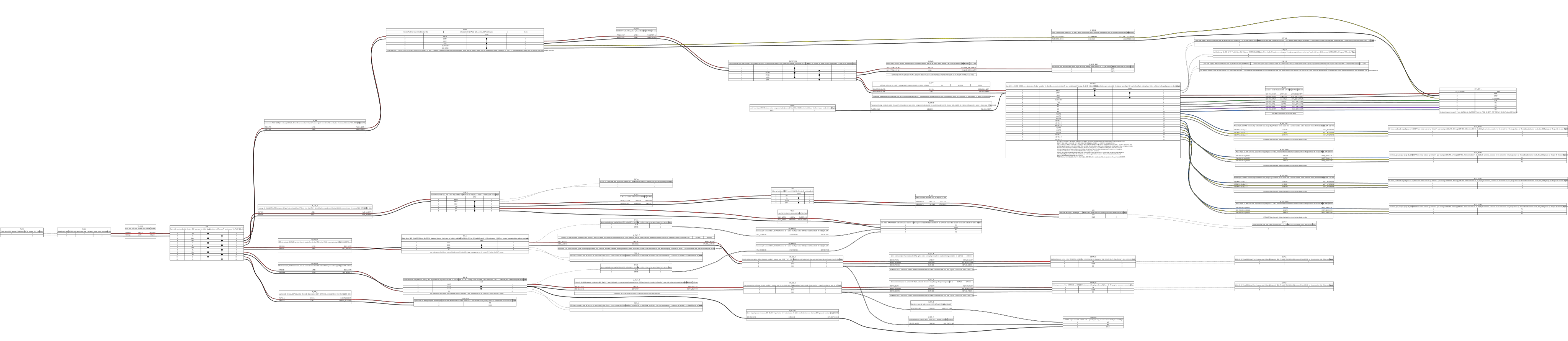
Select the drawing to open it at full size.
SUPERSEDED 2026-10-15: the SEN0697 cannot be bought (Ryan). The only flight compass is now the QMC5883L in the SEQURE
M10-25Q, which is also GPS2 on SERIAL4 (UART8, the underside pads TX8, RX8, 5V, GND; board file). Its compass leads
join the GPS port’s I2C3, the board’s only I2C bus, beside the MS4525DO (QMC5883L 0x0D, no address clash). Keep that
branch short. Identify each pin of the module’s connector before you connect it (th-eda): cheap “M10” modules
differ. The caution that follows applied to the SEN0697 only.
CAUTION (SEN0697 only, superseded): The external compass on Fuselage C, the DFRobot Fermion SEN0697 (parts list row 10b), is a 3.3 V
board. Do not connect it to the 5 V on pin 1 of the GPS port. Supply it through an AP2112K-3.3 regulator in its
lead (th-eda, 2026-10-10): the GPS port’s 5 V in, 1 uF at the input and 1 uF at the output, on a small strip in
heat-shrink tube. Do not take 3.3 V from the flight controller: a short in the lead must not stop the flight
controller’s logic supply. Connect four wires to the board’s 2.54 mm header: 3.3 V, GND, SCL and SDA, in 26 AWG,
with SCL and SDA twisted with GND. Do not connect INT1 to INT4. The I2C lines are 3.3 V logic, with the LUX’s
pull-ups to 3.3 V, and the board’s own pull-ups stay on. Before the first connection, measure the resistance
from SDA to 3V3 on the board with no power. If it is less than 2 kOhm, remove one pull-up resistor. If you use
the SH1.0 5-pin connector and not the header, identify each pin before you connect it. The board’s BMM350
(I2C address 0x15) is the compass. Its BMP581 (0x47) and BMI323 (0x69) are not used: BARO_PROBE_EXT stays 0,
and ArduPilot has no BMI323 driver. These addresses are clear of the LUX’s BMP280 (0x76), the MS4525DO (0x28)
and the Q43’s compass. The board takes less than 5 mA (th-eda, estimate).
Compass calibration on Fuselage C (th-avionics, 2026-10-11; compass changed 2026-10-15). The M10’s QMC5883L is the
only compass (COMPASS_DISBLMSK 1048576 turns off the Q43’s QMC5883P; the QMC5883L’s bit 12 stays clear). ArduPilot’s
QMC5883L driver applies ROLL_180 for an external chip, so COMPASS_ORIENT starts at 0 for the module upright with
its arrow forward (pending th-blender’s W52 hanger at Y 390 to 420 under the Bay roof); COMPASS_AUTO_ROT 2 corrects
the yaw part during the calibration. The distances below were measured from the SEN0697’s station and are pending
th-telemetry’s recheck for the M10’s place, which is aft and nearer the pusher motor and its ESC. The canopy has no magnets: it comes off on snap features (th-blender W17,
ba5ffa57). The Hatch is held at its fore end by two pairs of N52 20 x 10 x 5 mm blocks, one pair a side, about 289 mm
from the compass. One pair alone gives about 10 to 19 uT there, as large as the earth’s horizontal field (th-telemetry,
estimate). The two pairs are fitted antiparallel, port pair north up and starboard pair north down, so their fields
cancel on the centreline, where the compass is, and a small offset stays. With a pair reversed, the field at the
compass goes up to about 38 uT, and it moves with the Hatch’s seating (hardware-and-consumables.md, th-main 54d35440;
docs/agent-threads/fuselage-c/20261012T045509Z). Calibrate with the Hatch fitted.
- Fit the Hatch and the canopy, and close every other cover, before the calibration.
- If the beacon board is fitted, do not open a WiFi session on it during the calibration: its 2.4 GHz antenna is about 20 mm from the compass (th-telemetry). In flight the beacon radio is off. The first build has no beacon board (its seat carries the PM02).
- Do the compass calibration.
- Remove the Hatch and fit it again, two times. After each fit, compare the heading with the aircraft in the same position. It must stay within 1 degree. Do the same with the canopy.
- With the aircraft still, compare the heading with ELRS telemetry at full power on and off. It must stay within 1 degree (th-telemetry estimate: under 0.2 degree).
- If step 4 or 5 fails, find the cause before flight; first check the Hatch magnets’ polarity. Do not calibrate again with the Hatch off.
The 4-in-1 port follows the Betaflight connector order (VBAT, GND, current, telemetry, M1 to M4). Compare the 4-in-1’s own pin order on its silkscreen before you plug the cable in, and measure that pin 1 is battery positive. A reversed cable puts the battery voltage on a 3.3 V signal pin.
The 4-in-1’s signal lead to the ESC #1 port can be long (it was 223 mm in the Fuselage C cargo-bay layout; on v2.4B
the Lucid stands on edge ahead of the Spar Box, Y 245 to 276). Keep bidirectional DShot300 for a lead of 0.3 to 1 m (th-eda: a metre of lead is about 100 pF, and the
3.33 us bit and the RPM reply keep their margin). Do not add series resistors: the ESC drives the same wire back. Put
the four motor signals in the middle of the 8-wire lead with GND, VBAT and CURRENT around them, give the lead a loose
twist, and keep it 20 mm or more from the phase leads and the pack feed, with crossings at right angles. Bench check:
spin each lift motor and read ESC.Err (the RPM telemetry error rate, percent) in the log. It must stay near 0 and
must not rise with throttle. If it does not, first add a ground wire between the 4-in-1’s GND pad and the LUX’s,
along the lead. Set DShot150 only if that does not cure it or the lead is longer than about 1 m. lift_check.lua’s
motor checks use this RPM.
SUPERSEDED 2026-10-14 (the Lucid on edge ahead of the Spar Box on v2.4B; the compass is the M10’s since 2026-10-15). Was: the seat (th-blender afd4e5d): the 4-in-1 stands on edge across the aft end of the payload bay, board centre
(0.5, 506.2, 6.0), component side forward, battery tabs down, signal plug up; the lead to the ESC #1 port is 223 mm.
From the SEN0697’s compass IC: board centre 105 mm, nearest board point 98 mm, battery tabs 115 mm, the twisted feed
61 mm, the twisted phase bundles 59 mm (43 to 45 mm from the edge of the compass keep-out box), all routed away from
the compass as far as the bay walls allow; brass screws only. That is at or just under the 100 mm and 60 mm rules, so
the compass is proved on the bench, with the canopy on: calibrate the compass, fit COMPASS_MOT (tools/fit_compass_mot.py),
then run the four lift motors from idle through hover to about 75 %, aircraft still. The heading must stay within
3 degrees and the field strength within 10 %. If it does not, do not fly: the fallback is a DroneCAN compass in a
wing panel (th-telemetry), not a change of parameters.
The bay is sealed, so the 4-in-1 has no cooling but still air. th-eda estimates 12 to 24 W of heat in hover and
about 1 K a second of rise sealed: a 60 s hover adds about 60 K, and a 40 C day at the dock puts it near AM32’s
thermal limit. So an aluminium plate takes the heat from the exposed MOSFETs to the bay skin (th-blender). Bench
check, with the bay closed: two back-to-back 90 s runs at full-hover current on the thrust stand, with a thermocouple
on the hottest MOSFET, compared with the ESC’s own reading in the log (ESC.Temp, from the 4-in-1’s serial telemetry
on SERIAL5). The reading is the ESC MCU’s own die sensor, not the MOSFETs: it lags them and reads 10 to 20 K
lower under load (th-eda, estimate; the thermocouple measures it). The 4-in-1’s AM32 temperature limit stays DISABLED
(first-flight step 16, th-avionics a5eb5c7): past its limit AM32 cuts that motor’s output at once, which on a lift
motor in hover is a motor-out at the moment a landing needs every motor. Our own limits sit far below where AM32
would act (starting values until the bench runs): no arming above 70 C, and a warning in flight above 80 C on any
channel, which is the first-flight card’s land line (its CAUTION: land if any ESC channel reads more than 80 C in a
hover). No script reads the ESC temperature yet (2026-10-19; found by lux-765): the 70 C arming refusal and the
80 C warning are planned, not written, so until then the card’s 80 C land line is the only limit. The planned check
does not force a landing, because the landing is the heaviest load. After the bench runs, the card
and the script move together, from the measured hover rise and die-to-MOSFET offset, never one without the other.
Before the first unattended dock operation, the AM32 limit is set to 140 C, its highest valid value (th-eda): at the
dock nobody watches, and a lift ESC that keeps heating (a stuck command, a desync spinning a motor against the pad, a
test that does not end) can fail a MOSFET shorted across the 6S in a sealed bay. At 140 C on the die the MOSFETs are
near failure anyway (th-eda, estimate), so in a hover the motor is lost either way; at the dock the limit lets the ESC
throttle itself and survive. That step goes on the dock checklist, not the first-flight card.
SUPERSEDED 2026-10-15 (the SEN0697 is not used). Was: three cheap gains for the compass, taken (th-telemetry, th-avionics): the SEN0697 at the top of its keep-out box (Z 35), a 15 mm twist lay on the phase triples and the feed from Y 340 to 470, and the bundles low in the bay (Z -25) along that run.
Earlier first-flight board: HKUST NxtPX4v2 (Ryan, 2026-10-04, replaced the same day). The NxtPX4v2
(MicoAir) is an STM32H743 board with two BMI088 IMUs, an SPL06 barometer, 7 UARTs, 8 outputs, and 5 V
and 12 V BECs, on 20 × 20 mm holes. ArduPilot has its own target, NxtPX4v2, in the tree we build
(4c98c92). The parameters are in params/board-nxtpx4v2.parm; load it in place of the 6C Mini’s board
file, and do not load lift-4in1.parm with it (that file is written for the 6C’s IO co-processor, and its
SERIAL6 is this board’s RC input).
The NxtPX4v2 has no CAN. For first flights that was acceptable: the 4-in-1 needs no CAN, and the charge node and the rangefinder node are not first-flight items. It has these consequences:
- The airspeed sensor is an I2C MS4525DO (4525DO-DS5AI001DP: ±1 psi differential, I2C address 0x28,
5 V supply) on the board’s I2C pads, not the DroneCAN DLVR-L10D (
ARSPD_TYPE1,ARSPD_BUS1). It has its own straight pitot tube, which needs its own mount (th-blender): 99.5 mm long, 4 mm diameter, a 10 mm body, and the two spigot ends 15 mm apart (vendor drawing); the static port is a small hole near the tip. Before you connect it, measure the supply on the board’s I2C connector: it must be 5 V. - The board can fly only the 4-in-1. The DroneCAN pod ESCs need a CAN board.
- There is no charge node, so no charging in the dock.
- There is no output for the cargo-door servo.
| Output | Pad | Function | ArduPilot |
|---|---|---|---|
| 1-4 | PWM 1-4 (timer group 1-4) | Lift motors on the 4-in-1: DShot300, bidirectional DShot for RPM | SERVO1..4_FUNCTION 33, 35, 36, 34 (as on the LUX), Q_M_PWM_TYPE 5, SERVO_BLH_BDMASK 15 |
| 5, 6 | PWM 5, 6 (group 5-6, no motor) | Elevons left, right | SERVO5_FUNCTION 77, SERVO6_FUNCTION 78 |
| 7 | PWM 7 (group 7-8) | Pusher ESC, PWM | SERVO7_FUNCTION 70 |
| 8 | PWM 8 (group 7-8) | Survey3 camera trigger, PWM | SERVO8_FUNCTION 10 |
| - | AUX3 pad, J12 pin 1 (PA4, GPIO 81). ArduPilot’s README calls it AUX1; the board’s design nets and MicoAir’s sheet say AUX3 | “ON” input of the video switch | RELAY2_PIN 81, RELAY2_DEFAULT 1 |
| - | AUX2 pad, J12 pin 2 (PC1, GPIO 82) | Survey3 exposure feedback | CAM1_FEEDBAK_PIN 82 |
| Serial | UART | Use | ArduPilot |
|---|---|---|---|
SERIAL1 |
UART2 | Telemetry radio, MAVLink 2 | SERIAL1_PROTOCOL 2 |
SERIAL3 |
UART1 | Q43 GPS; its compass on the I2C pads (the board has no compass) | SERIAL3_PROTOCOL 5, GPS1_TYPE 2 |
SERIAL4 |
UART3 | HD video unit, MSP DisplayPort OSD. Pin 1 of this connector is 12 V | SERIAL4_PROTOCOL 42, OSD_TYPE 5 |
SERIAL5 |
UART7 | 4-in-1 serial telemetry | SERIAL5_PROTOCOL 16 |
SERIAL2 |
UART4, J5 | ELRS receiver, CRSF (both directions) | SERIAL2_PROTOCOL 23 |
SERIAL6 |
UART5, J7 | Not used: J7’s RX5 comes through the SBUS inverter, which inverts CRSF | SERIAL6_PROTOCOL -1 |
SERIAL7 |
UART8 | Spare | -1 |
Connectors, from the board’s open KiCad design (Peize-Liu/Nxt-FC-Hardware, branch NxtDual; th-blender read the pad nets, 2026-10-04). MicoAir’s production board matches it where th-blender could check, but not every net is proven:
| Connector | Pins | Use on TerraHawk |
|---|---|---|
| J3, GPS1 (6-pin SH 1.0, top) | 1 GND, 2 5 V, 3 UART1 TX, 4 RX, 5 I2C4 SCL, 6 SDA | The Q43 (GPS and compass), and the MS4525DO through the GPS and airspeed Y lead (parts list row 9f). The only external I2C; its pull-ups go to 3.3 V |
| J6, ESC (8-pin) | 1 BATT_I, 2 UART7 RX, 3-6 PWM 1-4, 7 VBAT, 8 GND |
A custom lead: the 4-in-1’s four signals and its telemetry wire, the PM02 V3’s current signal on pin 1, the pack voltage on pin 7 |
| J8, PWM_AUX (5-pin) | 1 GND, 2 PWM 8, 3 PWM 7, 4 PWM 5, 5 PWM 6 | Elevons (5, 6), pusher (7), camera trigger (8) |
| J7, RC (4-pin) | 1 GND, 2 5 V, 3 UART5 TX, 4 SBUS (inverted into RX5) | Not used; an SBUS receiver only |
| J5, TEL2 (4-pin) | 1 GND, 2 5 V, 3 UART4 TX, 4 RX | ELRS receiver, CRSF |
| J4, TEL1 (4-pin) | 1 GND, 2 5 V, 3 UART2 TX, 4 RX | Telemetry radio |
| J2, video (6-pin SH 1.0) | 1 CAM_9V, 2 GND, 3 UART3 TX, 4 RX, 5 GND, 6 SBUS |
The video unit and its OSD |
| J12, AuxGPIO (6-pin SH 1.0, bottom) | 1 AUX3 PA4, 2 AUX2 PC1, 3 AUX1 PC0, 4-6 SPI3 | Video switch ON (pin 1), camera strobe (pin 2). No power pin |
CAUTION: Before you connect the video unit, measure J2 pin 1. The open design names it CAM_9V, and
MicoAir specifies 12 V for the production board. The video unit’s input range must include it.
CAUTION: Before you connect the MS4525DO, measure J3 pin 2 (5 V), and measure the resistance from the sensor board’s SDA and SCL to its own 5 V pin. Pull-ups to 5 V on the sensor board would drive 5 V into the H743’s I2C pins. The sensor itself (4525DO-DS5AI001DP, the long-standing PX4 airspeed part) works on a bus pulled up to 3.3 V.
Power: the board measures the pack voltage itself (J6 pin 7). Connect the PM02 V3’s current signal to
J6 pin 1 (BATT_AMP_PERVLT 36.36, the PM02 V3’s scale). The PM02 measures the
whole pack current, the pusher included, so the battery failsafes stay correct.
Mount (th-blender 31824ff, Avionics Plate (NxtPX4v2)): face up, the arrow forward toward the ESC
connector’s edge, so AHRS_ORIENTATION 0. The connector side (RC, TELEM1, GPS1) is to starboard and
USB-C to port. Use one soft stage only: the board’s own soft-mount grommets. The FC mount
dampeners stay rigid PETG, because two soft stages in series can put a resonance near the lift
motors’ speed. The board has no internal IMU isolation, so do not leave out the grommets.
| Parameter | Value (m) | Source |
|---|---|---|
INS_POS1_*, INS_POS2_* (board file) |
-0.0257, 0.0079, -0.0272 | The two BMI088s’ midpoint, assembly (-7.90, 295.69, 21.61), from the open KiCad board on the plate. It is 7.9 mm to starboard: in the STL frame, +X is port. Z is an estimate: it uses 5 mm for the grommets. Measure the grommet height on the bench; each millimetre more makes Z 0.001 more negative |
Lift motors on a 4-in-1 to fly first (Ryan, 2026-09-29). The first build flies the TBS Lucid 60A 3-8S 4-in-1
(AM32, firmware target AM32_TBS_8S_4IN1_F421, the one Ryan bought; TBS rates it 4 × 50 A continuous, 60 A for 60 s,
85 A for 10 s; parts-list.md row 2b). On Fuselage C v2.4B it stands on edge in the Lucid Edge Bracket at Y 245 to
276, component side aft, battery tabs to starboard (Ryan, 2026-10-14). The LUX F765 drives it with bidirectional
DShot300 on outputs 1 to 4 through the ESC #1 connector, with its telemetry on SERIAL5; the board file sets the
DShot rows. Do not load params/lift-4in1.parm on the LUX: that file is for the Pixhawk 6C Mini’s IO co-processor.
The phase leads leave through the lift motor wire channels ahead of the front spar to the pods. Twist each motor’s
three phase leads together, one turn in 20 mm or less, for their whole length: this cuts their field at the compass.
Twist the pusher’s 12 AWG feed pair at 15 mm or less; it passes the M10’s compass at 65 mm or more with about 33 A in
a climb (th-telemetry). Brake on stop and motor direction are set on the ESC with the AM32 configurator. The first
hovers land if any channel reads more than 80 °C. The DroneCAN pod path in the next paragraph is the follow-on, one
pod at a time.
Lift motors on DroneCAN (decided 2026-09-27). Ryan asked for one ESC per lift motor at the
pod, as a DroneCAN node, on boards of ours designed with th-eda (AM32 firmware, STM32L431, the
Vimdrones S50’s firmware; th-eda’s pod board is now a 34 mm disc over the 30 mm pod pad, 2026-10-05, where the S50 is 40 x 17 mm). Bought AM32 DroneCAN ESCs are scarce, which is part of why the board is ours: the only
small one is the Vimdrones S50, whose product page showed “Sold out” on 2026-09-27 while the shop’s
own product data listed every variant as orderable (1 set $20.90, 4 sets $82.00; the data does not
say whether that is stock or backorder, so the checkout page decides). The only other one found
(Pogo, 40 A) sells through Chinese domestic channels, and Vimdrones’ development board was sold out.
A fly-first phase on four S50s plus a bench unit (about $103) remains worth having if they ship: a
reference unit answers the bring-up questions for our board and takes a first-spin ESC off the first
flight. Ryan decides at order time. If neither the S50s nor our board are ready when the airframe
is, the interim is four in-stock 6S 40 A single DShot ESCs in the same pod slots on the same DC
leads with a temporary signal harness from FC pads 1 to 4; that tests a different control path and
is only worth it to retire airframe risk early. The row for outputs 1 to 4 keeps its functions, but the
commands leave over the CAN bus, not the pads: CAN_D1_UC_ESC_BM 15 marks outputs 1 to 4 as CAN
ESCs, CAN_D1_UC_ESC_OF 0, Q_M_PWM_MIN 1000 and Q_M_PWM_MAX 2000. ArduPilot sends the four
commands in one CAN frame every main loop, and Plane sets SCHED_LOOP_RATE 300 for quadplanes, so
the motors update at 300 Hz for about 4 % of the bus. Pads 1 to 4 stay empty. The pusher keeps its
bought ESC, on AUX 5 of the 6C Mini (output 13, see the output map). The ESC nodes are 24 to 27 by ArduPilot motor number: motor 1 (front
starboard) 24, motor 2 (rear port) 25, motor 3 (front port) 26, motor 4 (rear starboard) 27. The bus
runs as one line through both booms (see charge-node.md). Our board has two CAN connectors and
passes it through. The bought S50 has one set of CAN pads, so in phase one each pod has a three-way
GH-4 joiner with a short pigtail to its S50, as the second diagram below shows. Source:
AM32 DroneCAN ESCs,
Vimdrones S50.

Select the drawing to open it at full size.
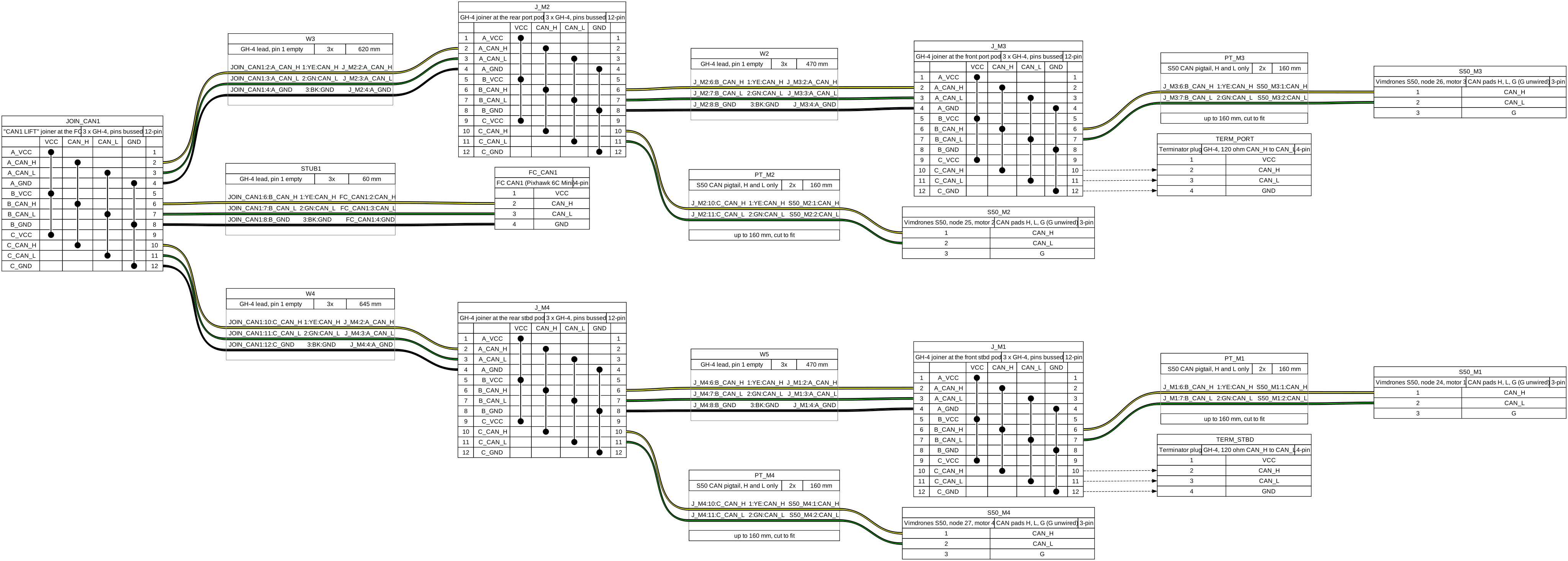
Select the drawing to open it at full size.
Our own flight controller (Ryan, 2026-09-27). Ryan decided the aircraft gets a flight
controller of ours, designed with th-eda: option A from the flight-controller thread. STM32H743 with
two CAN buses split by consequence: bus 1 carries the four lift ESCs and nothing else, bus 2 the
servo nodes, airspeed, GPS, rangefinder, charge node and payload. The elevon command stays PWM. The FC takes power exactly like the 6C Mini, through a Pixhawk POWER port fed by a power module on the main feed, so the harness is the same for both flight controllers; the servo and video rails stay on their own BECs (th-avionics, 2026-09-28).
The two buses are two DroneCAN drivers (CAN_P1_DRIVER 1, CAN_P2_DRIVER 2), never one driver
on both: one driver shares one transmit queue and memory pool across its interfaces, and a bus that
stops accepting frames holds every queued frame for up to 200 ms before it is marked down, which
would stall the lift ESCs’ commands (AP_Canard_iface.cpp, processTx). The servo nodes sit on both
buses (Ryan, 2026-09-27); their bus-1 transceiver is strapped listen-only unless the board is set to
command the servo over CAN, so bus 1 stays lift-only on aircraft that drive the elevons by wire. The
board routes the FDCAN3 pins to an unpopulated third transceiver position because the H743 and H723
share the LQFP-144 footprint; an H723 there is a 1 MB part, so a third bus would also mean a trimmed
1 MB ArduPlane build with Lua forced on, a firmware project, not a pin swap. Three native buses on a
2 MB part do not exist, and Lua is compiled out by default at 1 MB, which is why two buses. Build
order: lift ESC board, servo node, then the FC. Until it exists the aircraft flies a bought
Holybro Pixhawk 6C family board in place of the backordered Lucid; the 6C Mini fits the FC tray like
the Lucid (th-main, space map), the full 6C only raised 4 to 7 mm and 4 mm over the tray’s width.
From the avionics side the 6C Mini is enough: 2 CAN, 14 PWM (8 through the IO MCU, 6 from the
FMU), 2 telemetry and 2 GPS ports (ELRS, SiK, the GPS and the video link use all four),
ICM-42688-P and BMI088, MS5611, 54.3 x 39 x 17.5 mm, 42.4 g, one analog power module input. Ryan
chose the 6C Mini, Model A, with a PM02 V3 (2026-09-27). Its output map is in “Output map trap”
above. It has no 12 V video BEC, so that rail is a separate switched BEC (fpv-link.md). Sources:
Pixhawk 6C Mini specification,
Pixhawk 6C.
GPS: Waveshare Q43 NEO-F9P, directly on the FC (Ryan and th-telemetry, 2026-09-28; th-avionics
chose the connection). A u-blox NEO-F9P-15B with an L1/L5 helix and a QMC5883P compass in one
dome replaces the LC29H rover and its DroneCAN node. It connects to the 6C Mini’s GPS1 port (UART and
I2C) through a GH1.25 8-pin adapter cable, not through a node, for two reasons. The Q43’s GH1.25 8-pin
connector carries, in order along the connector as Waveshare draws it: GND, TX2, RX2, SDA, SCL, TX1, RX1,
VCC (3.3 to 16 V). TX1 and RX1 are the NEO-F9P’s UART1 (TX1 is its output), SDA and SCL the QMC5883P
compass (I2C address 0x2C), and TX2 and RX2 are not connected (Waveshare
docs). The drawing numbers no pin, so
find VCC and GND with a meter before the first power-up. The reasons for a direct connection: On CAN it would sit
on bus 2, and a bus 2 fault would then take the GPS and compass with the airspeed sensor; wired
directly, the aircraft keeps its position and heading and can still return when bus 2 dies. And an
F9P on a Pixhawk GPS port is ArduPilot’s most-flown configuration, with no board of ours in the path.
The O4 moves to GPS2. Parameters: GPS1_TYPE 2 (u-blox), SERIAL3_PROTOCOL 5, GPS1_RATE_MS 100,
GPS_DRV_OPTIONS 32 (bit 5, L5 health from L1, because GPS L5 is still pre-operational),
SERIAL4_PROTOCOL 42 for the O4, and COMPASS_TYPEMASK with bit 20 clear so the QMC5883P is probed;
its orientation is set from the dome’s mounting on the hatch. RTCM still arrives over the telemetry radio (the SX1262 LoRa link since 2026-10-04) and is
injected by the FC, and the one-RTCM-link rule is unchanged.
Sensor positions (th-avionics, 2026-09-28, from th-telemetry’s saddle, th-blender d7b33c4). The
body origin is the design CG, assembly (0, 270, -5.6), because every airframe is balanced to it before
flight; GPS_POS1 and INS_POS1/INS_POS2 are then offsets from that point in ArduPilot’s body
axes (X forward, Y right, Z down). GPS_POS1 goes in terrahawk-common.parm; INS_POS1/INS_POS2
go in each board file, because they belong to the board and its mount (since 2026-10-04).
| Parameter | Value (m) | Source |
|---|---|---|
GPS1_POS_X, _Y, _Z |
-0.030, 0.000, -0.057 | The Q43 on Fuselage C v2.4B: base centre (0, 300, 26.7) on the copper floor, phase centre at two-thirds of the 37.0 mm dome, Z 51.4 (th-telemetry 20261010T185835Z). From the design CG point (0, 270, -5.6), the origin of every GPS_POS and INS_POS. In the common file and in SITL’s SIM_GPS1_POS since th-simulator’s 7894390d (was -0.134, 0, -0.052, the earlier GPS saddle at Y 404). Waveshare publishes no phase centre, so this is an estimate, Z within about 10 mm |
GPS2_POS_X, _Y, _Z |
-0.139, 0.003, -0.053 | The SEQURE M10 (GPS2 and the compass) on the old SEN0697 hanger holes, assembly (-3, 409), patch top (th-blender W52.1 a5bd7623). In board-luxf765.parm |
INS_POS1_* (LUX F765) |
-0.0277, 0.0023, -0.0217 | The LUX’s one ICM42688 on Fuselage C v2.4B, assembly (-2.30, 297.70, 16.10), Z from the drawn Avionics Plate (th-blender W55 4530460e). In board-luxf765.parm and SITL’s SIM_IMU_POS since th-simulator’s 8d88360c (was -0.0236 from a 18.00 constant, and -0.0259 on Fuselage B’s deck). The LUX has no second IMU, so no INS_POS2_* |
INS_POS1_*, INS_POS2_* (6C Mini) |
-0.036, 0.000, -0.030 (both, placeholder) | The 6C Mini’s case centre, assembly (0, 305.65, 23.90) (th-blender, 2026-10-03). Replace with the two IMUs’ positions from Holybro’s drawing; a few millimetres of error here does not matter, the GPS lever arm does. In board-pixhawk6c-mini.parm since 2026-10-04 (in the common file from 2026-10-03): until 2026-10-03 no file set them, so the IMU was the de facto origin and GPS_POS1 was off by this offset (about 4.7 cm). SITL now uses the first-flight board’s values (the NxtPX4v2 row above), and make params checks them |
The 6C Mini is mounted turned 180° (Ryan, 2026-09-28), arrow aft, so its ports face aft into
the Hatch Rear opening instead of sitting under the Front/Mid joint: AHRS_ORIENTATION 4 (Yaw180).
That rotates the IMUs and the board’s internal compass only; ArduPilot applies the board orientation
to internal compasses and, for an external one, the driver’s own default rotation followed by
COMPASS_ORIENT (AP_Compass_Backend::rotate_field; ROTATION_ROLL_180 for the QMC5883P), so the
Q43’s compass is unaffected. Use the Q43 compass alone:
the internal one sits over the PM02’s current path, so set its COMPASS_USE to 0 once the
instances are known. The INS_POS placeholder above is recomputed from th-blender’s mirrored plate.
The saddle keys the dome with its connector forward, so COMPASS_ORIENT comes from the first
calibration and then stays in the common file. If a different pack moves the balanced CG, the
aircraft is re-ballasted to the design CG, not the parameters changed.
One airframe (Ryan, 2026-10-04). From 2026-09-27 the plan was two airframes sharing one set of
electronics; Ryan decided on one airframe on 2026-10-04. The identities are those of the one set: node ids 10 to 29 and the lights node’s 70, SYSID_THISMAV 1, one ELRS receiver, one telemetry radio
pair (the SX1262 LoRa link, which replaced the SiK on 2026-10-04; th-telemetry), and SITE_CLR carrying the cleared aircraft’s system id
(accepted by th-telemetry and th-hangar; harmless with one aircraft and ready for a second set).
The values measured on the aircraft are in airframe.parm, loaded after the common and board files.
| Airframe value | Why it is measured on the aircraft | Parameters |
|---|---|---|
| Board level | The FC mount is printed and bonded | AHRS_TRIM_X, AHRS_TRIM_Y (level calibration once) |
| Compass | The carbon spars, pack and power wiring near the GPS dome | COMPASS_OFS*, COMPASS_DIA*, COMPASS_ODI* from a full calibration; after work near the dome, check with the fixed-yaw calibration (MAV_CMD_FIXED_MAG_CAL_YAW, seconds on the pad). Then COMPASS_MOTCT 2 and COMPASS_MOT_* from a tied-down bench run, fitted by tools/fit_compass_mot.py (the 4-in-1’s leads pass 64 mm from the Q43; over 30 % interference, re-route instead) |
| Airspeed | The pitot position in the nose | ARSPD_RATIO from an airspeed calibration flight |
| Elevons | Linkage geometry and servo horns | SERVO5/6_TRIM, _MIN, _MAX, _REVERSED on the NxtPX4v2 (SERVO7/8_* on a board with the elevons on 7 and 8); the servo nodes’ wiper calibration if the servos stay in the wings |
| Airframe file loaded | A board without the calibrations must not fly | TH_AIRFRAME (a Lua script parameter) 1, set by the airframe file; th_prearm.lua refuses to arm while it is 0, which is its value until the airframe file has been loaded. The script adds the parameter, so load the flight scripts and reboot before you load the airframe file |
A rule that the parameters cannot enforce. Each lift ESC is labelled with its pod (motor number)
and goes back into the same pod position after any removal, because its node id and ESC index belong
to the pod. Motor direction is set in the ESC (AM32 DIR_REVERSED), so run the motor test and
check each direction after an ESC is changed, before the propellers go on.
Sources: ArduPilot autopilot list, Lucid H7 Wing doc, Kakute mapping, Kakute overview, BLITZ Wing doc, Matek H7A3-WING (EOL), Pixhawk 6C Mini spec, Plane 4.7.1.
Scripting memory check on the LUX F765
Section titled “Scripting memory check on the LUX F765”Do this check one time on the real board before the first flight, and again after a change to the flight
scripts. It is the “LUX memory check” on the checklist page (Ryan and th-avionics sign it). The first-flight card
gives the same pass values. The board’s default script memory is 100 KB. The eight first-flight scripts need more
than 200 KB in SITL (they did not load at 200 KB and loaded at 220 KB, th-testpilot 2026-10-15).
params/board-luxf765.parm sets SCR_HEAP_SIZE 225000 and LOG_FILE_BUFSIZE 16, for the day and the night build (since
2026-10-15; 240000 and 32 before). Do this check again after a change to either value.
The board comes with Betaflight. Step 1 replaces it. The LUX on Ryan’s bench had Betaflight 4.5.1 (board
LUXNDAAF7), and its settings were the factory defaults (backup betaflight-diff-all-20261015.txt, outside the
repository). Betaflight calls the chip “STM32F745”. That is the name of its build. The chip is an STM32F765 with
2 MB of flash, as the DFU flash map shows.
- Remove the USB cable. Put a microSD card in the slot. Use FAT32. A card of 64 GB or more is usually exFAT: format it as FAT32 first. ArduPilot does not boot on this board without a card.
- Flash ArduPlane, one time only. In the Betaflight CLI, send
bl: the board starts the STM32 DFU bootloader. Rundfu-util -l. The internal flash line must show04*032Kg,01*128Kg,07*256Kg(2 MB). If it shows fewer 256 KB sectors, stop: the image does not fit. Converthw/flight-controller/build/lux/arduplane_with_bl.hexto a .bin file. Write it withdfu-util -a 0 -s 0x08000000:leave -D <file>.bin. After the write, the board often does not come back on USB: remove the USB cable and connect it again. - Copy the files to the card, as first-flight card step 1 tells: the eight scripts to
APM/scripts, andth-clr-list.txtandmessage-intervals-chan1.txtto the root. Boot one time. Load the common, board and airframe parameter files. Make sure thatSCR_ENABLEis 1,SCR_HEAP_SIZEis 225000 andLOG_FILE_BUFSIZEis 16. SetLOG_DISARMEDto 1, so that the log also records the boot and the memory messages on the bench. Reboot. - Read the boot messages on the GCS. All eight load texts must show (first-flight card step 32). None of these texts must show: “Insufficent memory loading” (the ArduPilot spelling), “not enough mem” and “Scripting: failed to start”.
- Read MEMINFO
freemem(Mission Planner: the Status tab). This is the board memory that stays after the script memory. It must be more than 16 KB. - Add 2 to
SCR_DEBUG_OPTS(bit 1, runtime messages). Reboot. Set the GCS to show debug messages. Each script run then shows “Lua: Time: … Mem: …”. Wait 1 min. Record the highest Mem total. - Subtract 2 from
SCR_DEBUG_OPTS. SetLOG_DISARMEDto 0 (no parameter file sets it). Reboot. - Send the results to th-avionics: the date, the firmware
git_identity,freemem, the highest Mem total, any message from step 4, and the log from step 6.
The check passes when step 4 shows all eight load texts and none of the stop texts, and step 5 reads more than
16 KB. If it fails, do not make SCR_HEAP_SIZE smaller. th-avionics decides which script to remove.
Result, 2026-10-15 (Ryan’s LUX, ArduPlane 4c98c922, th-avionics): pass, after two board-file rows. At the
defaults the check failed hard: “EKF3 not enough memory” and “Terrain: Allocation failed” at boot, and freemem
about 1.7 KB. The scripts were not the problem. Their peak Lua use is 188,027 bytes, which is less than in SITL,
because SITL is a 64-bit program and every Lua pointer is twice as large. The board memory around the script heap was
too small. board-luxf765.parm now sets LOG_FILE_BUFSIZE 32 (the log write buffer, default 80 KB) and
TERRAIN_ENABLE 0 (no mission, failsafe or script of ours uses terrain data). With both rows: all eight load texts, no
memory text, freemem 24.6 KB lowest and 34.9 KB settled.
| Setting (heap 240000, eight scripts) | freemem lowest / settled |
Result |
|---|---|---|
| Defaults: log buffer 80 KB, terrain on | about 1.7 KB, EKF3 not allocated | Fail |
| Log buffer 32 KB, terrain on | 7.5 / 12.8 KB | Fail |
| Log buffer 16 KB, terrain on | 19.0 / 29.2 KB | Pass |
| Log buffer 32 KB, terrain off (filed) | 24.6 / 34.9 KB | Pass |
The bench also found four rows that the board does not have: INS_POS2_X, _Y and _Z (the LUX has one IMU) and
BRD_SER2_RTSCTS. They are removed from the board file. Turning terrain on again needs this check again.
Recheck and the night build, 2026-10-15 (Ryan’s LUX, ArduPlane 4c98c922, th-avionics). The scripts changed
(gps_loss_guard v2.5.1, the th_prearm v0.4 candidate), so the check was done again, and the night build was
checked for the first time: the eight scripts plus lights.lua, with params/payload-lights.parm (it turns the CAN
port on for the lights node). The script heap is one fixed block taken at boot, so a script does not take board
memory. The CAN driver does.
| Build and setting | Lua peak | freemem lowest / settled |
Result |
|---|---|---|---|
| Day, the filed values (heap 240000, log buffer 32 KB) | 193,382 B | 21.6 / 30.9 KB | Pass |
| Night, the filed values | 207,968 B | 10.7 / 12.7 KB, “EKF3 allocation failed” | Fail |
| Night, CAN off (for comparison only) | 21.0 / 31.1 KB | (pass) | |
| Night, log buffer 16 KB | 15.9 / 20.2 KB | Fail (16 KB) | |
| Night, log buffer 32 KB, DroneCAN pool 4096 | 12.3 / 17.9 KB, “EKF3 allocation failed” | Fail | |
| Night, log buffer 32 KB, heap 225000 | 14.5 / 15.4 KB | Fail | |
| Night, log buffer 16 KB, heap 225000 | 26.5 / 37.9 KB | Pass | |
| Day, log buffer 16 KB, heap 225000 | 51.2 / 62.8 KB | Pass | |
Day, the filed values (heap 225000, log buffer 16 KB), cg_slider v1.9 and th_prearm v0.4 adopted, 2026-10-16 |
194,325 B | 51.2 / 61.7 KB | Pass |
The CAN driver of the night build takes about 20 KB of board memory, and at a 240000 heap and a 32 KB log buffer EKF3
cannot allocate. The aircraft cannot arm without its EKF, so the failure shows on the ground. So the board file sets
LOG_FILE_BUFSIZE 16 and SCR_HEAP_SIZE 225000 for the two builds (Ryan, 2026-10-15). One setting for the two builds
keeps both names gated by the checklist: a value in an overlay file would remove a name from the gated list
(tools/checklist_code.py). The heap keeps 31 KB above the day build’s Lua peak and 17 KB above the night build’s. The
16 KB log buffer can drop log messages in bursts: read the dropped count (Dp) after the first flights (first-flight
card). SITL is a 64-bit program, so its Lua peak is larger than the board’s: SITL flies its own heap, 300000 for every
row (th-testpilot 1820ed71), and does not test the board’s memory.
Flight controller candidates (checked 2026-09-24)
Section titled “Flight controller candidates (checked 2026-09-24)”This comparison is from 2026-09-24, before Fuselage C. The first build flies the LUX F765.
The two Amazon boards below are from the same hardware family. Corvon is the manufacturer (corvon.tech). Aero Selfie is a rebrand with an identical specification sheet.
| Board | ASIN | Notes |
|---|---|---|
| Corvon H743 + 60A 8-bit 4-in-1 stack | B0GTTPDCSH | $84.99. FC is fine, ESC is 8-bit (BLHeli_S), see below |
| Corvon H743 FC only | B0GTTLG3NH | |
| Aero Selfie H743 + 60A 32-bit stack | B0F9PJFG3C | The variant to prefer if buying this family |
| Aero Selfie H743 + 60A 8-bit stack | B0GHMXQGLW | |
| Aero Selfie H743 FC only | B0DQY1SCW9 |
The ArduPilot support is real, not a marketing claim. The target is CORVON743V1, and it has
an official wiki page (https://ardupilot.org/plane/docs/common-corvon743v1.html). The first
flash is by DFU with the _with_bl.hex. After the first flash, you can load the .apj from
any GCS.
These are the specifications that are important for this airframe:
- STM32H743, dual IMU (BMI088 + BMI270), DPS310 baro, IST8310 compass, OSD chip.
- 7 UARTs. Defaults: UART1/4 MAVLink, UART2 DisplayPort, UART3 GPS, UART6 RC in, UART7 ESC telemetry.
- 10 outputs in three timer groups: 1 to 4, 5 to 6, 7 to 10. All the outputs can use DShot. The layout from the output map trap above fits: lift motors on 1 to 4 (DShot), pusher ESC on 5 (PWM), elevon servos on 7 and 8. No servo shares a group with a motor.
- BECs: 5V 3A and 9V 3A. The 5V rail can supply two 12g metal-gear servos, the receiver and the GPS. But it is not the dedicated servo rail that a wing board has.
- Battery: onboard voltage sense to 6S. Current sense is only through the current pin of the ESC. Thus, the current value comes from the 4-in-1 stack ESC. The board is not rated for 8S.
Verdict: this family is acceptable as a budget substitute for the basic route on 6S. It does not have the advantages of a wing board (dedicated servo BEC, onboard current sensor, more UARTs, usually two battery inputs). If you buy this family, buy the 32-bit ESC stack. The list specifies BLHeli_32 or AM32 on the lift ESC for DShot300 with ESC telemetry. The 8-bit stack can turn the motors, but you do not get telemetry for each ESC.
The FC mount of that time was a plain 40 x 88mm tray with no bolt pattern, so a 30.5 x 30.5 stack attached to it with standoffs or tape.
Motor candidates
Section titled “Motor candidates”FFTY 3115 900KV 4-pack (Amazon B0GDPXJZHN, $79.99)
Section titled “FFTY 3115 900KV 4-pack (Amazon B0GDPXJZHN, $79.99)”This motor is not a lift motor. The list specifies four 2807-class motors (2806.5 to 3008 stators), 1050 to 1250KV on 6S with an 8-inch bi-blade. Each motor is approximately 40 to 60g. A 3115 is in the pusher class. It is approximately double the weight, and its winding is for 9 to 11 inch props. Four of them at the spar tips add much more than 200g, at the location where weight causes the most problems. Also, 900KV on 6S with an 8-inch prop gives less RPM than the recommended KV range.
3115 900KV as the pusher
Section titled “3115 900KV as the pusher”This is the correct class. 900KV is the 4S winding. The 6S winding is 640KV. The ArduPilot values in the manual are for 6S. Thus, on a 6S build, the correct pusher is 640KV (T-Motor VELOX V3115 640KV, BrotherHobby Tornado T5 3115 640KV, EMAX ECO II 3115 640KV). Buy the whole powertrain for one voltage.
Motor mount bolt pattern (measured from the STLs)
Section titled “Motor mount bolt pattern (measured from the STLs)”Both printed motor mounts have four M3 (3.1mm) holes on a 13.4mm square. The distance from corner to corner is 19mm. The holes are around a 9.7mm centre hole (pusher) or an 11mm centre hole (VTOL).
Motor vendors give “19x19” or “19mm”. This is the bolt-circle diameter, not the distance from hole to hole. Thus, all the motors on the recommended list fit. Refer to parts-list.md for the resolution and the sources.
Harness checks before first power-up
Section titled “Harness checks before first power-up”Do these checks on the bench with the harness in the airframe, before the pack is connected for the first
time. Use the XT90 smoke stopper (parts-list.md, row 14) for the first connection of the pack.
The aircraft side of the main lead is an XT90-S (anti-spark) male, and the pack keeps its standard XT90 female (Ryan, 2026-10-04). Its pre-charge contact fills the bus capacitance through a resistor before the main contact closes. Push the plug fully home in one firm movement. Do not stop with it partly in: in that position the resistor carries the current, and it gets hot.
WARNING: Remove all props before the first power-up. A wiring fault can start a motor.
- PM02 cable. Holybro does not publish the pinout of the PM02 V3’s GH-6 header. The 1:1 match to the
flight controller’s POWER port is inferred from the cable it ships with (th-eda,
terrahawk-eda/docs/fc-connectors-6c-mini.md). Before you connect it to a flight controller, measure the cable end to end with a meter. The order must be pin 1 and 2: 5 V, pin 3: current, pin 4: voltage, pin 5 and 6: GND. Do this check again for our own flight controller. - CAN termination. With all power off, measure the resistance between CAN_H and CAN_L on each bus, at
any free header (the bus diagrams are in “Lift motors on DroneCAN” above and in
charge-node.md). The value must be about 60 Ω: the two 120 Ω terminator plugs in parallel. About 120 Ω means that one terminator plug is missing. About 40 Ω means that a node has its terminator switched on. This check cannot see the airspeed sensor’s terminator, which is switched by software and is open with the power off. Check that one by its parameter (see the setup steps). - Servo supply. Before you connect a servo, measure the 5 V output of each Micro BEC (row 9j) with no load. Matek gives it as 5 V and does not publish the tolerance, so record the values. Each must be from 5.0 to 5.3 V. If the BEC12S-PRO is fitted in their place, it must be 5.2 V. The Hitec MD65MG is rated from 4.8 to 6.0 V. Fit the 1000 uF capacitor at the servo end of each run and apply power. The voltage at the capacitor must rise one time and stay. If it rises and falls again and again, the over-current protection of the BEC is cycling: stop. Then load each run with 2 A at the servo plug (an electronic load, or a 2.5 Ohm 10 W resistor) for 5 s or less: the BEC gives 1.5 A continuously and 2.5 A for 5 s. Measure the drop from the output pads of the BEC to the plug. It must be 150 mV or less. Then connect the servos, hold one elevon against its stop, and measure at that servo’s plug. It must be 4.8 V or more.
- Servo plugs on the 6C Mini. Holybro does not publish the pitch of the 6C Mini’s servo header. It measures about 2.8 by 2.55 mm on Holybro’s drawing. Before you cut the servo leads, fit a standard 2.54 mm servo plug on the header and make sure that it seats fully. Our own flight controller takes the same leads on a vertical 3 x 10 header at 2.54 mm, in the same row order (signal, servo rail, GND), with the plugs from above.
- Video supply. Before you connect the video unit, measure the 12 V output of power hub A (row 9h). It must be 12 V.
- Polarity at each supply input. After the pack plug is changed to XT90-S, measure the polarity at the BATT pads of hub A, at its 470 uF capacitor, and at the input pads of the two Micro BECs, before the first connection. The BEC12S-PRO, if fitted, has no reverse-polarity protection.
- S50 CAN ground pads. Make sure that the CAN G pad of each bought S50 is not wired (
charge-node.md, bus 1 grounding).
At the first power-up, through the smoke stopper:
- The idle current must stay under 1 A with no motor turning (an estimate; the flight controller, the receivers, the telemetry radio and the nodes draw a few hundred mA together). A higher current means a fault: disconnect.
- In the GCS, read the flight controller’s 5 V (
POWRin the log or the board voltage). It must be 5.0 to 5.4 V. - On Mission Planner’s DroneCAN page, check the node list on each bus: bus 1 shows the four lift ESCs, ids 24 to 27; bus 2 shows the charge node (20), the airspeed sensor (21), and the rangefinder node (22) when it is fitted. A node on the wrong bus means a crossed harness.
- Then do the setup steps: board orientation, calibrations, and the ESC settings in “AM32 settings on every lift ESC”, with props off for the motor test.
- Supply input spikes (the Micro BECs feed the elevons, Ryan 2026-10-15). On the thrust stand, with a full pack (25.2 V) and the props on, connect an oscilloscope across the input pads of one Micro BEC, with its ceramic capacitors fitted, and set it to single-shot trigger. A meter’s max-hold is too slow for a brake-stop spike (th-eda). Run all four lift motors up to the cap and cut the throttle to zero, five times (the lift ESCs brake on stop). The peak must stay under 29 V: the input maximum of the BEC is 30 V. Do the check at the second BEC too. If a peak is 29 V or more, stop: do not fly until the BEC12S-PRO (9 to 55 V input) replaces the two Micro BECs. Do the same check at the BATT pads of hub A, with its 470 uF capacitor fitted: there the peak must stay under 26 V, the input maximum of the hub.
The source files this page describes, as they are in the repo.
docs/images/harness/can-bus1-lift.yml · 71 lines · open · download
# CAN bus 1, LIFT, phase two (th-eda lift ESC boards). v1 from th-main's data,# agent-threads/harness/20260928T051244Z-th-main-can-bus-harness-data.md (fadaa43).# The harness stays in the airframe; ESCs and the FC unplug. Pin 1 (VCC) is empty on all of bus 1.# Terminator plugs go straight into the front pods' free headers (no end leads).# CAN GND at each ESC reaches board ground through 10 ohm (th-eda decision 2026-09-28): the wire# otherwise parallels the pod's 16 AWG power return and would carry ~1 A at 25 A and ~2 A at 50 A# (ESTIMATE), past the GH 1 A contact rating; the pod-to-FC ground offset stays under 0.3 V, well# inside the TJA1051's +-12 V common-mode range.metadata:  title: TerraHawk CAN bus 1 (lift), phase two, v1  notes: "GH-4 pinout 1 VCC (empty on bus 1), 2 CAN_H, 3 CAN_L, 4 GND. Lengths in mm from th-main (7598bf5, thread 20260928T053336Z): pod ends 110 mm; phase two stows about 70 mm spare per pod end under the duct."
connectors:  M3_FRONT_PORT: &esc    type: Lift ESC (th-eda rev A), node 26, motor 3    subtype: 2 x GH-4, passed through; GND via 10 ohm to board ground    pinlabels: [A_VCC, A_CAN_H, A_CAN_L, A_GND, B_VCC, B_CAN_H, B_CAN_L, B_GND]    shorts: {VCC: [1, 5], CAN_H: [2, 6], CAN_L: [3, 7], GND: [4, 8]}  M2_REAR_PORT: {<<: *esc, type: "Lift ESC (th-eda rev A), node 25, motor 2"}  M4_REAR_STBD: {<<: *esc, type: "Lift ESC (th-eda rev A), node 27, motor 4"}  M1_FRONT_STBD: {<<: *esc, type: "Lift ESC (th-eda rev A), node 24, motor 1"}  TERM_PORT: &term    type: Terminator plug    subtype: GH-4, 120 ohm CAN_H to CAN_L    pinlabels: [VCC, CAN_H, CAN_L, GND]  TERM_STBD: *term  JOIN_CAN1:    type: '"CAN1 LIFT" joiner at the FC'    subtype: 3 x GH-4, pins bussed, no terminator    pinlabels: [A_VCC, A_CAN_H, A_CAN_L, A_GND, B_VCC, B_CAN_H, B_CAN_L, B_GND, C_VCC, C_CAN_H, C_CAN_L, C_GND]    shorts: {VCC: [1, 5, 9], CAN_H: [2, 6, 10], CAN_L: [3, 7, 11], GND: [4, 8, 12]}  FC_CAN1:    type: FC CAN1 (Pixhawk 6C Mini; th-eda FC later)    pinlabels: [VCC, CAN_H, CAN_L, GND]    notes: CAN_P1_DRIVER 1
cables:  W2: &lead    type: GH-4 lead, pin 1 empty    wirecount: 3    wirelabels: [CAN_H, CAN_L, GND]    colors: [YE, GN, BK]    length: 470 mm    notes: front port pod to rear port pod  W3: {<<: *lead, length: 620 mm, notes: rear port pod to the FC joiner}  STUB1: {<<: *lead, length: 60 mm, notes: joiner to FC CAN1}  W4: {<<: *lead, length: 645 mm, notes: FC joiner to rear stbd pod}  W5: {<<: *lead, length: 470 mm, notes: rear stbd pod to front stbd pod}
connections:  - - TERM_PORT: [2-4]    - [-->, -->, -->]    - M3_FRONT_PORT: [2-4]  - - M3_FRONT_PORT: [6-8]    - W2: [1-3]    - M2_REAR_PORT: [2-4]  - - M2_REAR_PORT: [6-8]    - W3: [1-3]    - JOIN_CAN1: [2-4]  - - JOIN_CAN1: [6-8]    - STUB1: [1-3]    - FC_CAN1: [2-4]  - - JOIN_CAN1: [10-12]    - W4: [1-3]    - M4_REAR_STBD: [2-4]  - - M4_REAR_STBD: [6-8]    - W5: [1-3]    - M1_FRONT_STBD: [2-4]  - - M1_FRONT_STBD: [6-8]    - [-->, -->, -->]    - TERM_STBD: [2-4]
docs/images/harness/can-bus1-lift-phase1.yml · 97 lines · open · download
# CAN bus 1, LIFT, phase one: bought Vimdrones S50 ESCs (one CAN pad set each) on the same harness# cables as phase two. A GH-4 joiner at every pod takes the harness legs plus the S50's 80 mm# pigtail; at a front pod the terminator plug goes in the joiner's third header. Phase two removes# the pod joiners. Joiner headers (th-main 7598bf5; header 1 nearest the spar slot): rear pod 1 = leg from# the FC tee, 2 = leg to the front pod, 3 = S50 pigtail; front pod 1 = leg from the rear pod, 2 = S50# pigtail, 3 = terminator plug. In this file header 1/2/3 are the joiner pins A/B/C (1-4, 5-8, 9-12). The S50's G pad is left UNWIRED (it is grounded through its power leads; see the# ground-loop note in can-bus1-lift.yml).metadata:  title: TerraHawk CAN bus 1 (lift), phase one with S50s, v1
connectors:  J_M3: &join    type: GH-4 joiner at the front port pod    subtype: 3 x GH-4, pins bussed    pinlabels: [A_VCC, A_CAN_H, A_CAN_L, A_GND, B_VCC, B_CAN_H, B_CAN_L, B_GND, C_VCC, C_CAN_H, C_CAN_L, C_GND]    shorts: {VCC: [1, 5, 9], CAN_H: [2, 6, 10], CAN_L: [3, 7, 11], GND: [4, 8, 12]}  J_M2: {<<: *join, type: GH-4 joiner at the rear port pod}  J_M4: {<<: *join, type: GH-4 joiner at the rear stbd pod}  J_M1: {<<: *join, type: GH-4 joiner at the front stbd pod}  JOIN_CAN1: {<<: *join, type: '"CAN1 LIFT" joiner at the FC'}  S50_M3: &s50    type: Vimdrones S50, node 26, motor 3    subtype: CAN pads H, L, G (G unwired)    pinlabels: [CAN_H, CAN_L, G]  S50_M2: {<<: *s50, type: "Vimdrones S50, node 25, motor 2"}  S50_M4: {<<: *s50, type: "Vimdrones S50, node 27, motor 4"}  S50_M1: {<<: *s50, type: "Vimdrones S50, node 24, motor 1"}  TERM_PORT: &term    type: Terminator plug    subtype: GH-4, 120 ohm CAN_H to CAN_L    pinlabels: [VCC, CAN_H, CAN_L, GND]  TERM_STBD: *term  FC_CAN1:    type: FC CAN1 (Pixhawk 6C Mini)    pinlabels: [VCC, CAN_H, CAN_L, GND]
cables:  W2: &lead    type: GH-4 lead, pin 1 empty    wirecount: 3    wirelabels: [CAN_H, CAN_L, GND]    colors: [YE, GN, BK]    length: 470 mm  W3: {<<: *lead, length: 620 mm}  STUB1: {<<: *lead, length: 60 mm}  W4: {<<: *lead, length: 645 mm}  W5: {<<: *lead, length: 470 mm}  PT: &pig    type: S50 CAN pigtail, H and L only    wirecount: 2    wirelabels: [CAN_H, CAN_L]    colors: [YE, GN]    length: 160 mm    notes: up to 160 mm, cut to fit  PT_M3: *pig  PT_M2: *pig  PT_M4: *pig  PT_M1: *pig
connections:  # front port pod: 1 leg from the rear pod, 2 S50, 3 terminator  - - J_M2: [6-8]    - W2: [1-3]    - J_M3: [2-4]  - - J_M3: [6-7]    - PT_M3: [1-2]    - S50_M3: [1-2]  - - J_M3: [10-12]    - [-->, -->, -->]    - TERM_PORT: [2-4]  # rear port pod: 1 leg from the FC tee, 2 leg to the front pod, 3 S50  - - JOIN_CAN1: [2-4]    - W3: [1-3]    - J_M2: [2-4]  - - J_M2: [10-11]    - PT_M2: [1-2]    - S50_M2: [1-2]  - - JOIN_CAN1: [6-8]    - STUB1: [1-3]    - FC_CAN1: [2-4]  # rear stbd pod: 1 leg from the FC tee, 2 leg to the front pod, 3 S50  - - JOIN_CAN1: [10-12]    - W4: [1-3]    - J_M4: [2-4]  - - J_M4: [10-11]    - PT_M4: [1-2]    - S50_M4: [1-2]  - - J_M4: [6-8]    - W5: [1-3]    - J_M1: [2-4]  # front stbd pod: 1 leg from the rear pod, 2 S50, 3 terminator  - - J_M1: [6-7]    - PT_M1: [1-2]    - S50_M1: [1-2]  - - J_M1: [10-12]    - [-->, -->, -->]    - TERM_STBD: [2-4]
docs/images/harness/can-bus2.yml · 86 lines · open · download
# CAN bus 2, first flight: airspeed (node 21, software terminator, nose end) -> charge node sense# board (node 20, J1 in / J2 out) -> "CAN2" joiner at the FC with a 60 mm stub to CAN2 and the# terminator plug in its third header. Range node (22) and servo nodes (28, 29) are later slots.# Airspeed module in the Fuselage Front's port lobe (th-avionics decision, th-main 91af504, 2026-09-28):# no cone crossing. Joiner on the floor ahead of the battery bay (th-blender b250fba): J1 a 133 mm stub from the module# (software terminator OFF), J2 the terminator plug, J3 the trunk to sense board J1 (385 mm with the P50B,# 200 with the Tattu). th-main 6c3e93b.# All bus leads are crimped (SSHL-002T-P0.2, 28 AWG, four colours); the kit's pre-crimped GH leads are 150 mm.# The bus end is terminated at the joiner, not at the module, so a loose module plug loses only the# airspeed, never the termination (th-avionics, cart H11).# Bus 2 carries VCC: the charge node's MCU and transceiver run from bus 5 V (through its load switch).# Source: th-main, agent-threads/harness/20260928T051244Z-th-main-can-bus-harness-data.md (fadaa43).metadata:  title: TerraHawk CAN bus 2, first flight, v1  notes: GH-4 pinout 1 VCC (5 V from the FC), 2 CAN_H, 3 CAN_L, 4 GND.
connectors:  AIRSPEED:    type: Airspeed module, node 21, Fuselage Front port lobe    subtype: GH-4, software terminator OFF (stub; th-avionics 2026-09-28)    pinlabels: [VCC, CAN_H, CAN_L, GND]  JOIN_FWD:    type: Joiner beside the airspeed module (Fuselage Front, port lobe)    subtype: 3 x GH-4, pins bussed (boards/can-joiner rev A); floor ahead of the battery bay, X -36 to -7, J1 at the X -36 end    pinlabels: [A_VCC, A_CAN_H, A_CAN_L, A_GND, B_VCC, B_CAN_H, B_CAN_L, B_GND, C_VCC, C_CAN_H, C_CAN_L, C_GND]    shorts: {VCC: [1, 5, 9], CAN_H: [2, 6, 10], CAN_L: [3, 7, 11], GND: [4, 8, 12]}  CHARGE_J1:    type: Charge node sense board J1 (CAN IN), node 20    pinlabels: [VCC, CAN_H, CAN_L, GND]  CHARGE_J2:    type: Charge node sense board J2 (CAN OUT)    subtype: J1 and J2 bussed on the board, JP1 open    pinlabels: [VCC, CAN_H, CAN_L, GND]  JOIN_CAN2:    type: '"CAN2" joiner at the FC'    subtype: 3 x GH-4, pins bussed, no terminator    pinlabels: [A_VCC, A_CAN_H, A_CAN_L, A_GND, B_VCC, B_CAN_H, B_CAN_L, B_GND, C_VCC, C_CAN_H, C_CAN_L, C_GND]    shorts: {VCC: [1, 5, 9], CAN_H: [2, 6, 10], CAN_L: [3, 7, 11], GND: [4, 8, 12]}  FC_CAN2:    type: FC CAN2 (Pixhawk 6C Mini)    pinlabels: [VCC, CAN_H, CAN_L, GND]    notes: CAN_P2_DRIVER 2, supplies bus 5 V  TERM_FWD: &termplug    type: Terminator plug, bus 2 forward end    subtype: GH-4, 120 ohm CAN_H to CAN_L    pinlabels: [VCC, CAN_H, CAN_L, GND]  TERM_AFT:    type: Terminator plug    subtype: GH-4, 120 ohm CAN_H to CAN_L    pinlabels: [VCC, CAN_H, CAN_L, GND]
cables:  W_FWD: &lead4    type: GH-4 lead, crimped 28 AWG    wirecount: 4    wirelabels: [VCC, CAN_H, CAN_L, GND]    colors: [RD, YE, GN, BK]    length: 385 mm    notes: "trunk: forward joiner J3 to sense board J1; 385 with the P50B incl. hatch loop, 200 with the Tattu (th-main 6c3e93b)"  STUB_AS: {<<: *lead4, length: 133 mm, notes: "STUB: airspeed module (GH port faces aft, th-blender 5f1012f) to joiner J1, plug from below"}  W_BAY: {<<: *lead4, length: 236 mm, notes: "routed, with hatch loop"}  STUB2: {<<: *lead4, length: 60 mm, notes: joiner to FC CAN2}
connections:  # forward joiner (th-main 6c3e93b): J1 stub from the module, J2 terminator plug, J3 trunk to the sense board  - - AIRSPEED: [1-4]    - STUB_AS: [1-4]    - JOIN_FWD: [1-4]  - - JOIN_FWD: [5-8]    - [-->, -->, -->, -->]    - TERM_FWD: [1-4]  - - JOIN_FWD: [9-12]    - W_FWD: [1-4]    - CHARGE_J1: [1-4]  - - CHARGE_J1: [1-4]    - [--, --, --, --]    - CHARGE_J2: [1-4]  - - CHARGE_J2: [1-4]    - W_BAY: [1-4]    - JOIN_CAN2: [1-4]  - - JOIN_CAN2: [5-8]    - STUB2: [1-4]    - FC_CAN2: [1-4]  - - JOIN_CAN2: [9-12]    - [-->, -->, -->, -->]    - TERM_AFT: [1-4]
docs/images/harness/power-distribution.yml · 459 lines · open · download
# Power distribution, first flight (LUX F765, PM02 V3, two Matek Power Hub V2.1), v1, 2026-10-08; v3 2026-10-11: the Lucid# 4-in-1 (lift) on its own ducted ESC hatch, the pusher ESC on its own 12 AWG feed, the lights node's 6S lead for its 5.2 V# supply only (the dock charges the 2S).# v4, 2026-10-14, Fuselage C v2.4B (Ryan picked it 2026-10-13): the Lucid on edge across the bay ahead of the Spar Box, so# no hatch and no disconnects (the XT90 hatch plug, the four MR60 pairs and the SH-8 coupler are gone): the feed and the# three bulk caps are soldered to its battery tabs, the phase triples run straight to the motors, the SH-8 lead straight to# the LUX. Sources: th-blender W36 (20261014T020437Z, 23e04b22), W36.2 (20261014T025055Z, 4a3d620d) and its# aero/fuselage-c/v24b-internals.json routes; th-telemetry 20261014T020800Z (the plate's strap); docs/lucid-bulk-caps.md.# Every v2.4B length is th-blender's ESTIMATE from CAD.# v5, 2026-10-15 (Ryan): hub B, the servo Y lead and its 1000 uF are gone. Two Matek Micro BECs (MBEC6S, row 9j) clip into# hub A's pad (th-blender W53 6611f51d), each on its own 24 AWG tap from the pack side of the PM02 with the row 9k ceramics# at its input pads; BEC A feeds the starboard servo, BEC B the port servo, each through its own 20 AWG run soldered to the# BEC's output pads, spliced to the servo extension at the conduit's inboard seal, with a 1000 uF (row 9i) at the servo end# (th-avionics electronics-notes 06a05a60: loop 75 mOhm or less; 20 AWG with one connector joint, or 18 AWG throughout# with two). Servo-supply sense: each BEC's output pads, A1 for BEC A and A2 (GPIO28) for BEC B (th-eda 2026-10-15).# Lengths from W53's lead table (ESTIMATE, polyline x 1.15).# Source (v1 to v4): th-avionics electronics-notes.md eeea9fc ("Two Matek Power Hub V2.1 boards", "Harness checks before first# power-up") and parts-list.md rows 2g, 9b, 9d, 9e, 9h, 9i, 15a, 15b; lights.md for the lights node's 6S lead.# The pack's XT90 female mates the aircraft's XT90-S (anti-spark) male. The two hubs and the lights node tap the# PACK side of the PM02 V3, so the PM02 reads the lift ESC and the pusher, not the hubs. Hub A (port bay wall):# 12 V to the video unit through the video switch, 5 V to the CG slider servo and its XIAO RP2040. Until v4, hub B# (starboard bay wall) fed the elevon servo Y lead, never the flight controller; the LUX F765 makes its own 5 V from# the pack through the 4-in-1's ESC lead (ESC #1 pin 1 VBAT, Betaflight order). Hub A approved by Ryan 2026-10-09# (th-blender 68392f1). Spike tests (electronics-notes checks 5 and 6, th-avionics 06a05a60): on a full pack through# five full-cap brake stops on the thrust stand, the peak must stay under 26 V at hub A's BATT pads and under 29 V at# each Micro BEC's input pads, else the Matek BEC12S-PRO replaces the two Micro BECs before flight.# Capacitors (th-eda, DigiKey provider 2026-10-08): 470 uF 50 V at hub A's BATT pads and at the video unit's 12 V# input, parts list row 2g (Panasonic EEU-FR1H471, out of stock; Nichicon UHE1H471MPD 493-1613-ND in stock);# 1000 uF 10 V at each servo end, row 9i (Panasonic EEU-FR1A102, P124221-ND); since v5 no 470 uF at hub B (gone).# BEC input ceramics, row 9k (th-eda, DigiKey provider 2026-10-15): two TDK CNC6P1X7R1H106K250AE 10 uF 50 V X7R 1210,# soft termination (445-181655-1-ND; C3225X7R1H106K250AC, 445-C3225X7R1H106K250ACCT-ND, if it runs out) and one Murata# GCM188R71H104KA57D 100 nF 50 V X7R 0603 (490-4779-1-ND) a BEC. At the Lucid's tabs, row 2e: three Rubycon# 35PZJ560M10X15 560 uF 35 V hybrids, 1680 uF, for TBS's manual section 13.5 (1000 uF or more within 1 cm of lead for 25# to 29 mm motors) and the hover ripple (docs/lucid-bulk-caps.md); they replace three EEU-FR1H101 100 uF 50 V.# Servo-supply monitor (th-avionics f16e0a2; v5 th-eda): per BEC a 22k/22k divider (row 17k), the top 22 k at the BEC's# OUT pad so a chafed sense wire to ground draws 0.23 mA and cannot load the BEC, the lower 22 k and 100 nF (row 17g) at# the XIAO: BEC A into A1 (GPIO27), BEC B into A2 (GPIO28).# Wire gauges: 10 AWG main feed and PM02 leads (row 15b), 12 AWG pusher feed (charge-node.md), 20 AWG hub A's tap# (ESTIMATE from about 2 A), 24 AWG BEC taps (W53; about 0.6 A at a 2.5 A output, ESTIMATE), 20 AWG servo runs, 26 AWG# signals and sense.metadata:  title: TerraHawk power distribution, first flight, v5 (Fuselage C v2.4B, two Micro BECs)  date: 2026-10-15  notes: >    Hub A and the two Micro BECs tap the pack side of the PM02, each on its own lead; BEC A feeds the starboard elevon,    BEC B the port. Neither BEC feeds the flight controller. The LUX takes VBAT from the 4-in-1's ESC lead    and the PM02's current signal on ESC #1 pin 3. Before first power-up: checks 1, 3, 5 and 6 of electronics-notes.md.    v4 (2026-10-14) follows Fuselage C v2.4B, th-blender W36 / W36.1 / W36.2; v5 (2026-10-15) the Micro BECs, W53;    lengths are ESTIMATES from CAD.    Not drawn: the LUX's right-angle USB-C pigtail, 58 mm, tied at the Lucid bracket's bridge 26 mm along (not a power wire).
connectors:  PACK:    type: Flight pack, 6S2P Molicel P50B (row 13)    subtype: XT90 female, 25.2 V full    pinlabels: [+, -]  MAIN:    type: Aircraft main lead    subtype: XT90-S male (anti-spark, row 15a); push home in one movement    pinlabels: [+, -]  TAP:    type: Pack-side junction (hub A, the two BEC taps and the lights lead)    subtype: solder joint or XT-series T, pack side of the PM02 V3    pinlabels: [IN+, IN-, PM+, PM-, A+, A-, BA+, BA-, BB+, BB-, L+, L-]    shorts: {+: [1, 3, 5, 7, 9, 11], -: [2, 4, 6, 8, 10, 12]}  PM02:    type: Holybro PM02 V3 power module (row 9e)    subtype: re-leaded with 10 AWG; 120 A sense, 60 A continuous    pinlabels: [BATT+, BATT-, OUT+, OUT-, CURRENT, SIG_GND]    shorts: {GND: [2, 4, 6]}    notes: GH-6 order 5 V, 5 V, CURRENT, VOLTAGE, GND, GND (check 1); only CURRENT and a GND are used; on Fuselage C in the beacon board's empty seat on the Beacon Carrier, centre (10.75, 294.5, -2.1) (th-blender 9c636da), until the beacon flies; unchanged in v2.4B  JUNCTION:    type: Lift and pusher split after the PM02, a soldered lap splice 25 mm from the PM02's OUT pads (heat-shrunk; th-blender SPLICE_AT)    subtype: 10 AWG in; 10 AWG on to the Lucid's battery tabs, 12 AWG to the pusher ESC    pinlabels: [+, -, PUSH+, PUSH-, LIFT+, LIFT-]    shorts: {+: [1, 3, 5], -: [2, 4, 6]}  ESC4IN1:    type: Lucid 4-in-1 lift ESC (AM32), on edge across the bay ahead of the Spar Box, component side aft, tabs to starboard (Fuselage C v2.4B, th-blender W36)    subtype: feed and bulk caps soldered to the battery tabs; 8-pin SH lead in Betaflight order; phase triples soldered to the pad groups; no disconnects    pinlabels: [BATT+, BATT-, VBAT, GND, CURRENT, TLM, M1, M2, M3, M4, x0y17 1, x0y17 2, x0y17 3, x0y38.5 1, x0y38.5 2, x0y38.5 3, x1y17 1, x1y17 2, x1y17 3, x1y38.5 1, x1y38.5 2, x1y38.5 3]    shorts: {VBAT: [1, 3], GND: [2, 4]}    notes: |      Its own CURRENT pin stays unwired; the PM02 V3 measures the whole pack and takes that pin on the LUX.      Battery tabs: tab 1 (lower, Z -10.6 to 0.7) and tab 2 (upper, Z 3.1 to 14.4) are the two polarities;      tab 1 (lower) is MINUS and tab 2 (upper) is PLUS (Ryan 2026-10-14: minus left seen from the GH-1.25 face, which is the      aft-facing component side; th-blender W36.4). Pads on both faces; the feed and the plate strap land on the component side.      Phases: each triple lap-soldered sideways along its pad group, a flat ribbon on the pack-side face over a      0.4 mm Kapton-faced spacer (39.8 mm for the y17 groups, 25.7 for the y38.5 groups), tied once through its      own 2 mm hole, then a twisted bundle from the end plate's window.      Motors are labelled by pad group and side: th-blender's note gives no M1 to M4 map, so which pad group is      which Betaflight motor on the SH lead is to be settled against the Lucid's channel map before the leads      are cut (a swapped motor pair is a crash).      AM32 thermal limit disabled for the first flights, 140 C before unattended dock operation (th-avionics a263857).  CAP_L1:    type: Lucid bulk cap A1, 560 uF 35 V hybrid (row 2e), Rubycon 35PZJ560M10X15 (1189-35PZJ560M10X15-ND)    subtype: ahead of the duct wall centred on the tabs' X, in Cradle A; leads straight aft through 1.4 mm bores in the wall onto the tabs' pack-side face, 7.6 mm each (ESTIMATE, within TBS's 1 cm; W36.4)    pinlabels: [+, -]  CAP_L2:    type: Lucid bulk cap A2, 560 uF 35 V hybrid (row 2e), Rubycon 35PZJ560M10X15    subtype: beside A1 in Cradle A; leads on one diagonal through an angled bore onto the tabs' pack-side face, 11.4 mm each (ESTIMATE; bulk beyond TBS's rule; W36.4)    pinlabels: [+, -]  CAP_L3:    type: Lucid bulk cap B1, 560 uF 35 V hybrid (row 2e), Rubycon 35PZJ560M10X15    subtype: on the front spar's top in Cradle B; leads 26.2 mm to tab 1 (minus) and 15.3 mm to tab 2 (plus), legs paired (ESTIMATE; bulk beyond TBS's rule; W36.4 corrected W36.2's 12.0)    pinlabels: [+, -]    notes: 'The three in parallel: 1680 uF (TBS manual 13.5 asks 1000 uF within 1 cm, met by A1 with the board; docs/lucid-bulk-caps.md). The stripe (minus) lead of every can goes to tab 1, the lower tab. Bench check: scope the tabs during braked spool-downs from the throttle cap, peak under 35 V'  PLATE:    type: Lucid heat plate / GNSS shield on the component side (reserved; fitted if the GNSS noise test fails or the thrust stand needs it, th-telemetry)    pinlabels: [GND]  MOT_X0Y17: &motor    type: Lift motor, starboard, on pad group x0 y17    subtype: 2807; front or rear pod set by th-main's spar routing and the M1..M4 map (SERVO1..4 functions 35, 34, 33, 36) by th-avionics, checked on the bench; the y17 groups leave by the starboard channel mouth, the y38.5 groups by the port (th-blender 2026-10-14)    pinlabels: [P1, P2, P3]  MOT_X0Y38: {<<: *motor, type: "Lift motor, port, on pad group x0 y38.5"}  MOT_X1Y17: {<<: *motor, type: "Lift motor, starboard, on pad group x1 y17"}  MOT_X1Y38: {<<: *motor, type: "Lift motor, port, on pad group x1 y38.5"}  PUSHER_ESC:    type: Pusher ESC, the Aria on its tray in the Bay's aft cavity (battery leads at about (0, 522); th-blender W4)    subtype: 12 AWG feed from the junction    pinlabels: [BATT+, BATT-]  LUX_ESC1:    type: LUX F765 ESC #1 port, 8 pins in Betaflight order (not the NxtPX4v2's J6)    pinlabels: [VBAT, GND, CURRENT, TLM, M1, M2, M3, M4]    notes: the board makes its own 5 V from VBAT (pin 1); CURRENT from the PM02 V3 (BATT_AMP_PERVLT 36.36), TLM on SERIAL5 16  HUB_A:    type: Matek Power Hub V2.1, hub A (row 9h), port bay wall    subtype: input 7 to 26 V; 12 V 2 A and 5 V 3 A; ESC pads unused    pinlabels: [BATT+, BATT-, 12V+, 12V-, 5V+, 5V-]    shorts: {GND: [2, 4, 6]}  CAP_A:    type: 470 uF 50 V low-ESR (row 2g) across hub A's BATT pads    subtype: Nichicon UHE1H471MPD (493-1613-ND); polarity check 6    pinlabels: [+, -]  VSW:    type: Video switch (row 9c)    subtype: ON from LUX AUX3 (J12 pin 1), not drawn    pinlabels: [IN+, IN-, OUT+, OUT-]    shorts: {GND: [2, 4]}  CAP_V:    type: 470 uF 50 V low-ESR (row 2g) at the video unit's 12 V input    subtype: Nichicon UHE1H471MPD (493-1613-ND)    pinlabels: [+, -]  VTX:    type: Walksnail Avatar HD Moonlight, 12 V in    subtype: about 1.4 A; never from the LUX's 9 to 10 V rail, never from the pack    pinlabels: [12V, GND]  SLIDER:    type: CG slider, XIAO RP2040 and continuous-rotation servo    subtype: hw/cg-slider; A1 (GPIO27) reads BEC A, A2 (GPIO28) reads BEC B; each lower 22 k and 100 nF at the XIAO    pinlabels: [5V, GND, A1, A2]  BEC_A: &bec    type: Matek Micro BEC 6S (MBEC6S, row 9j), BEC A, starboard elevon; clip-in slot on hub A's pad (W53)    subtype: 6 to 30 V in, 5 V out (9 V pad left open), 1.5 A continuous, 2.5 A 5 s a minute; four castellated pads on one end    pinlabels: [OUT, GND, GND, IN]    shorts: {GND: [2, 3]}    notes: pad order along the 10 mm end as Matek prints it (mbec6S_1.jpg); input pair at the IN corner, 5 V pair at the OUT corner  BEC_B: {<<: *bec, type: "Matek Micro BEC 6S (MBEC6S, row 9j), BEC B, port elevon; clip-in slot on hub A's pad (W53)"}  CER_A: &cer    type: BEC input ceramics (row 9k) across IN and GND, in the 12 x 8 x 3 mm volume aft of the pads    subtype: 2 x TDK CNC6P1X7R1H106K250AE 10 uF 50 V 1210 (soft termination) + 1 x Murata GCM188R71H104KA57D 100 nF 0603    pinlabels: [+, -]  CER_B: {<<: *cer}  DIV_A: &div    type: Servo-supply divider, top half (row 17k), at the BEC's OUT pad    subtype: 22 k inline in the sense wire, heat-shrunk at the pad    pinlabels: [OUT, SENSE]  DIV_B: {<<: *div}  SPLICE_A: &splice    type: Run-to-extension splice at the starboard conduit's inboard seal (X 54, Y 347, Z 2; W53)    subtype: soldered and heat-shrunk; the extension's signal core leaves here for the LUX    pinlabels: [5V, GND, SIG]  SPLICE_B: {<<: *splice, type: "Run-to-extension splice at the port conduit's inboard seal (X -54, Y 347, Z 2; W53)"}  CAP_S: &capservo    type: 1000 uF 10 V low-ESR (row 9i) at the servo end of the run    subtype: Panasonic EEU-FR1A102 (P124221-ND), across 5 V and GND on the extension side of the servo plug    pinlabels: [+, -]  CAP_P: {<<: *capservo}  SERVO_P:    type: Port elevon servo, Hitec MD65MG, on BEC B    subtype: 4.8 V minimum at the plug under stall (check 3); JR plug, the run's one connector joint    pinlabels: [5V, GND, SIG]  SERVO_S:    type: Starboard elevon servo, Hitec MD65MG, on BEC A    subtype: 4.8 V minimum at the plug under stall (check 3); JR plug, the run's one connector joint    pinlabels: [5V, GND, SIG]  LUX_OUT:    type: LUX F765 output pads M5 and M6 with a ground    subtype: signal only; no servo rail on the flight controller    pinlabels: [M5, M6, GND]  LIGHTS_J1:    type: Lights node J1, 6S pigtail pads (boards/lights)    subtype: 2 A fuse and SMAJ33A on the node; feeds its 5.2 V diode-OR and V_6S only (the dock charges the 2S since 2026-10-11)    pinlabels: [6S, GND]
cables:  W_MAIN:    type: Main feed, silicone 10 AWG (row 15b)    wirecount: 2    wirelabels: [+, -]    colors: [RD, BK]    gauge: 10 AWG  W_PM:    type: Junction to PM02 BATT (the in-lead), 10 AWG, 68 to 86 mm over the CG slider's travel (pack front 90 to 74; cut 86 plus the bend; th-blender W36, ESTIMATE)    wirecount: 2    wirelabels: [+, -]    colors: [RD, BK]    gauge: 10 AWG  W_OUT:    type: PM02 OUT to the lift / pusher splice, 10 AWG    wirecount: 2    wirelabels: [+, -]    colors: [RD, BK]    gauge: 10 AWG    length: 25 mm  W_LIFT:    type: Lift feed, splice to the Lucid's battery tabs (component side), 10 AWG, soldered    wirecount: 2    wirelabels: [+, -]    colors: [RD, BK]    gauge: 10 AWG    length: 42 mm    notes: ESTIMATE. th-blender W36.2 gives the feed as 67 mm from the PM02's OUT pads straight to the tabs (route 66.9 in v24b-internals.json); the splice sits 25 mm along it, so about 42 mm from the splice  W_PUSH:    type: Pusher feed, 12 AWG twisted, from the splice beside the lift feed, then on aft to the Aria in the Bay's aft cavity (th-blender W36.2)    wirecount: 2    wirelabels: [+, -]    colors: [RD, BK]    gauge: 12 AWG    length: 253.5 mm    notes: ESTIMATE, from the splice to the Aria along the drawn route in v24b-internals.json (th-blender 2026-10-14; the 246 in W36.2 was stale)  W_TAP_A: &tap    type: Hub tap, 20 AWG (ESTIMATE from about 2 A per hub), twisted; hub A 70 mm from the XT90's aircraft half, re-routed round the Lucid (v24b-internals.json 69.8, was 59.8; ESTIMATE)    wirecount: 2    wirelabels: [+, -]    colors: [RD, BK]    gauge: 20 AWG  W_TAP_BA: &beccap    type: BEC A input pair, 24 AWG twisted, from its bank aft under the XT90 to the PM02's pack-side tap (W53)    wirecount: 2    wirelabels: [+, -]    colors: [RD, BK]    gauge: 24 AWG    length: 79 mm  W_TAP_BB: {<<: *beccap, type: "BEC B input pair, 24 AWG twisted, from its bank aft under the XT90 to the PM02's pack-side tap (W53)", length: 74 mm}  W_TAP_L: {<<: *tap, type: "Lights node 6S lead, 20 AWG pigtail (the node draws about 0.2 A, ESTIMATE), twisted, 60 mm from the Q43"}  W_SENSE:    type: PM02 current signal to the LUX, 26 AWG, about 20 mm under the LUX's plate (straight line, not yet routed; th-blender 9c636da)    wirecount: 2    wirelabels: [CURRENT, GND]    colors: [YE, BK]    gauge: 26 AWG  W_ESC:    type: Lucid's 8-pin SH lead direct to LUX ESC #1, out of the board's port end, twisted with its ground, under the copper floor's plane (th-blender W36); the ESC's CURRENT core left out (the PM02's goes in its place); DShot300    wirecount: 7    wirelabels: [VBAT, GND, TLM, M1, M2, M3, M4]    colors: [RD, BK, GN, WH, GY, VT, BU]    gauge: 24 AWG    length: 109 mm    notes: ESTIMATE, 108.6 mm (th-blender W36)  W_PH_X0Y17: &phase    type: Phase triple, 16 AWG silicone, lap-soldered to pad group x0 y17, ribbon on the board then a twisted bundle, to the starboard motor (th-blender W36)    wirecount: 3    wirelabels: [P1, P2, P3]    colors: [BU, YE, WH]    gauge: 16 AWG    length: 117 mm    notes: ESTIMATE from the pads, ribbon included; colours for the drawing only  W_PH_X0Y38: {<<: *phase, type: "Phase triple, 16 AWG silicone, lap-soldered to pad group x0 y38.5, ribbon on the board then a twisted bundle, to the port motor (th-blender W36)", length: 86 mm}  W_PH_X1Y17: {<<: *phase, type: "Phase triple, 16 AWG silicone, lap-soldered to pad group x1 y17, ribbon on the board then a twisted bundle, to the starboard motor (th-blender W36)", length: 118 mm}  W_PH_X1Y38: {<<: *phase, type: "Phase triple, 16 AWG silicone, lap-soldered to pad group x1 y38.5, ribbon on the board then a twisted bundle, to the port motor (th-blender W36)", length: 86 mm}  W_STRAP:    type: Plate ground strap, single, to tab 1, the Lucid's minus (lower) tab, on the component side beside the feed minus (Ryan / th-blender W36.4, 2026-10-14); never the positive tab or a phase pad (th-telemetry)    wirecount: 1    wirelabels: [GND]    colors: [BK]  W_12V:    type: Hub A 12 V to the video switch, 20 AWG    wirecount: 2    wirelabels: [12V, GND]    colors: [RD, BK]    gauge: 20 AWG  W_VTX:    type: Video switch to the video unit, 20 AWG    wirecount: 2    wirelabels: [12V, GND]    colors: [RD, BK]    gauge: 20 AWG  W_5A:    type: Hub A 5 V to the CG slider, 22 AWG    wirecount: 2    wirelabels: [5V, GND]    colors: [RD, BK]    gauge: 22 AWG  W_RUN_A: &run    type: 5 V run A, 20 AWG twisted, soldered to BEC A's OUT and GND pads (no connector), aft outboard of the XT90, under the beacon carrier's aft end and behind the rear spar to the starboard conduit's seal (W53)    wirecount: 2    wirelabels: [5V, GND]    colors: [RD, BK]    gauge: 20 AWG    length: 260 mm    notes: 'ESTIMATE. The whole loop, BEC pads to servo plug with the plug contacts, must be 75 mOhm or less (electronics-notes 06a05a60): 20 AWG with one connector joint (the servo plug) is about 133 mV at a 2 A stall over 699 mm; with a second joint, 18 AWG throughout'  W_RUN_B: {<<: *run, type: "5 V run B, 20 AWG twisted, soldered to BEC B's OUT and GND pads (no connector), aft outboard of the XT90 and straight through the Spar Box's port side to the port conduit's seal (W53)", length: 183 mm, notes: "ESTIMATE. As run A: about 123 mV at a 2 A stall over 622 mm with one joint"}  W_EXT_A: &ext    type: Servo extension (row 7a, twisted 20 AWG), splice to the servo plug through the starboard wing conduit    wirecount: 3    wirelabels: [5V, GND, SIG]    colors: [RD, BK, WH]    gauge: 20 AWG    length: 279 mm    notes: ESTIMATE, W53's 439 mm of conduit and servo lead less the MD65MG's own 160 mm lead (row 7a); the 1000 uF sits at this cable's plug end  W_EXT_B: {<<: *ext, type: "Servo extension (row 7a, twisted 20 AWG), splice to the servo plug through the port wing conduit"}  W_SIG_A: &sig    type: Starboard elevon signal, splice to the LUX's M6 pad, 26 AWG    wirecount: 1    wirelabels: [SIG]    colors: [WH]    gauge: 26 AWG  W_SIG_B: {<<: *sig, type: "Port elevon signal, splice to the LUX's M5 pad, 26 AWG"}  W_SENSE_A: &sns    type: Servo-supply sense, BEC A, 26 AWG from the 22 k at the OUT pad to the XIAO (lower 22 k and 100 nF there)    wirecount: 1    wirelabels: [SENSE]    colors: [WH]    gauge: 26 AWG  W_SENSE_B: {<<: *sns, type: "Servo-supply sense, BEC B, 26 AWG from the 22 k at the OUT pad to the XIAO (lower 22 k and 100 nF there)"}  W_FCGND:    type: Servo signal ground reference, BEC B's GND pad to the LUX output pads, 26 AWG, one for both servos (the two BEC grounds meet at the tap)    wirecount: 1    wirelabels: [GND]    colors: [BK]    gauge: 26 AWGconnections:  # pack to the pack-side junction  - - PACK: [1-2]    - [--, --]    - MAIN: [1-2]  - - MAIN: [1-2]    - W_MAIN: [1-2]    - TAP: [1-2]  # PM02 and the pod / pusher junction  - - TAP: [3-4]    - W_PM: [1-2]    - PM02: [1-2]  - - PM02: [3-4]    - W_OUT: [1-2]    - JUNCTION: [1-2]  - - JUNCTION: [5-6]    - W_LIFT: [1-2]    - ESC4IN1: [1-2]  # bulk caps and the plate's strap on the Lucid's battery tabs  - - ESC4IN1: [1-2]    - [--, --]    - CAP_L1: [1-2]  - - ESC4IN1: [1-2]    - [--, --]    - CAP_L2: [1-2]  - - ESC4IN1: [1-2]    - [--, --]    - CAP_L3: [1-2]  - - PLATE: [1]    - W_STRAP: [1]    - ESC4IN1: [2]  # phase triples, soldered both ends  - - ESC4IN1: [11-13]    - W_PH_X0Y17: [1-3]    - MOT_X0Y17: [1-3]  - - ESC4IN1: [14-16]    - W_PH_X0Y38: [1-3]    - MOT_X0Y38: [1-3]  - - ESC4IN1: [17-19]    - W_PH_X1Y17: [1-3]    - MOT_X1Y17: [1-3]  - - ESC4IN1: [20-22]    - W_PH_X1Y38: [1-3]    - MOT_X1Y38: [1-3]  - - JUNCTION: [3-4]    - W_PUSH: [1-2]    - PUSHER_ESC: [1-2]  - - PM02: [5-6]    - W_SENSE: [1-2]    - LUX_ESC1: [3, 2]  - - ESC4IN1: [3, 4, 6, 7, 8, 9, 10]    - W_ESC: [1-7]    - LUX_ESC1: [1, 2, 4, 5, 6, 7, 8]  # hub A: video and the CG slider  - - TAP: [5-6]    - W_TAP_A: [1-2]    - HUB_A: [1-2]  - - HUB_A: [1-2]    - [--, --]    - CAP_A: [1-2]  - - HUB_A: [3-4]    - W_12V: [1-2]    - VSW: [1-2]  - - VSW: [3-4]    - W_VTX: [1-2]    - VTX: [1-2]  - - VTX: [1-2]    - [--, --]    - CAP_V: [1-2]  - - HUB_A: [5-6]    - W_5A: [1-2]    - SLIDER: [1-2]  # the two Micro BECs: one each for the elevon servos, on hub A's pad  - - TAP: [7-8]    - W_TAP_BA: [1-2]    - BEC_A: [4, 3]  - - BEC_A: [4, 3]    - [--, --]    - CER_A: [1-2]  - - BEC_A: [1-2]    - W_RUN_A: [1-2]    - SPLICE_A: [1-2]  - - SPLICE_A: [1-3]    - W_EXT_A: [1-3]    - SERVO_S: [1-3]  - - SERVO_S: [1-2]    - [--, --]    - CAP_S: [1-2]  - - SPLICE_A: [3]    - W_SIG_A: [1]    - LUX_OUT: [2]  - - BEC_A: [1]    - [--]    - DIV_A: [1]  - - DIV_A: [2]    - W_SENSE_A: [1]    - SLIDER: [3]  - - TAP: [9-10]    - W_TAP_BB: [1-2]    - BEC_B: [4, 3]  - - BEC_B: [4, 3]    - [--, --]    - CER_B: [1-2]  - - BEC_B: [1-2]    - W_RUN_B: [1-2]    - SPLICE_B: [1-2]  - - SPLICE_B: [1-3]    - W_EXT_B: [1-3]    - SERVO_P: [1-3]  - - SERVO_P: [1-2]    - [--, --]    - CAP_P: [1-2]  - - SPLICE_B: [3]    - W_SIG_B: [1]    - LUX_OUT: [1]  - - BEC_B: [1]    - [--]    - DIV_B: [1]  - - DIV_B: [2]    - W_SENSE_B: [1]    - SLIDER: [4]  - - BEC_B: [2]    - W_FCGND: [1]    - LUX_OUT: [3]  # lights node  - - TAP: [11-12]    - W_TAP_L: [1-2]    - LIGHTS_J1: [1-2]
Source: docs/electronics-notes.md in the repo. Edit it there; this page is generated.
Comments
Comment on the whole page here, or on one section or step with the button beside it.