
Thrust stand
The thrust stand measures one motor on the bench at a time: the thrust, the current and the pack voltage at each throttle step. Until it runs, the current and thrust figures in Propulsion are model values. The stand is a bench tool, not a part of the aircraft, and its cost is not in the flight cart total.
To build it, follow Build the thrust stand.
thrust-stand-64 designs the stand in its own repository (../thrust-stand, commit f50c24b, 2026-10-12). th-eda chose the electronics, and th-main sliced the prints and keeps the parts list.
| Item | Status, 2026-10-19 |
|---|---|
| Design | Done for the stand and the electronics. The display is a 2.0 in colour TFT that Ryan already has (2026-10-18). The box tub stands free on four TPU feet in place of its wood-screw flanges (Ryan, 2026-10-19), and it is not final: it waits on the insert coupon’s result |
| Parts | Priced at $311.05 in the parts list, with the corded emergency stop, the rotary encoder, the keyswitch interlock and the sensors (th-main ba8bd0b8, a02a6141, e64630a0; 2026-10-18 and 19). The XT90 plugs come from the aircraft’s spares (row 15a). Ryan already has the 10 kg load cell and an HX711 |
| Prints | The stand’s parts are printed: the motor bracket, the square-nut pillar, the two XT90 mounts and the insert coupon (thrust-stand-21, 2026-10-18). The first motor bracket had layer shifts and is scrap; Ryan used it only to test the fit of the load cell. The box tub and lid wait for the lid redraw |
| Firmware | Written and unit tested (64 native tests, thrust-stand), not flashed. The safety rules on this page are the design it follows |
| Tests | None yet: nothing has spun |
What the stand checks
Section titled “What the stand checks”The pass marks are in To check on the thrust stand. Each result goes to the session that uses it.
| Check | Result goes to |
|---|---|
| The pusher at full throttle for 10 seconds on a fresh pack: the current, and the vibration of the prop | th-aeronautics |
| The pusher stopped with the brake on: the blades fold aft with no airflow | th-aeronautics |
| One lift motor with the 3-blade F8041 at hover thrust: the current | th-aeronautics |
| One lift motor at full throttle, the duty capped at 0.82 and then increased in steps of 0.01 while the current stays under 49 A: the highest step that holds, and thrust against duty | th-avionics (Q_M_SPIN_MAX, Q_M_THST_EXPO) |
| One lift motor from a braked stop, blades folded, to hover throttle: the time to 90 % of hover thrust | th-avionics and th-eda; the stall test card sets its recovery floor from it |
Do not run the 3-blade lift prop at full throttle without the duty cap. The model gives about 64 A, more than the motor’s 52 A peak.
The stand
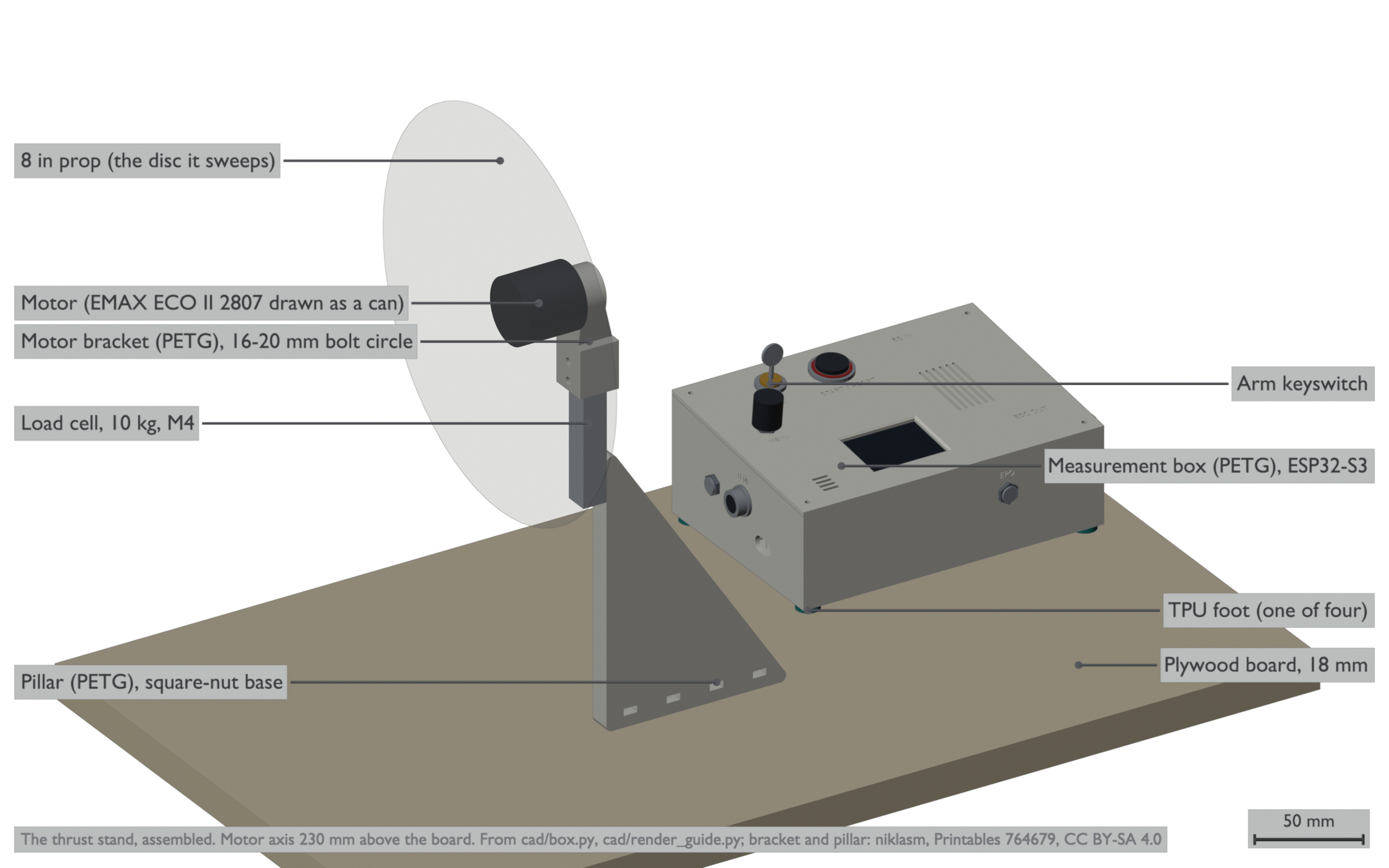
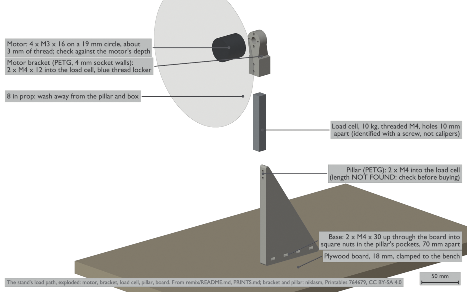
Section titled “The stand”The stand is niklasm’s Automated Thrust Testing Stand (Printables 764679, CC BY-SA 4.0), changed for these motors and this load cell. The load cell is a cantilever. One end is bolted to a printed pillar. The motor is on a printed bracket at the free end. The motor pushes the bracket, and the load cell bends. Ryan’s NOYITO 10 kg load cell has threaded M4 holes, 10 mm apart (confirmed with a screw, 2026-10-12).
| Change | Why |
|---|---|
| The four motor slots of the large bracket are 0.5 mm longer, for a bolt circle of 16 to 20 mm | The EMAX ECO II 2807 and 3115 have four M3 on a 19 mm bolt circle. The original slots stop at 19.0 mm, and printed slots are usually small |
| The four walls of the bracket’s load-cell socket are 4 mm thick, not 2 mm, with a 2.5 mm chamfer into the original taper. The motor plate is then 12.95 mm thick | Ryan: the socket fits the load cell, and its walls must be stronger. The 12.9 x 12.9 x 25 mm socket and its M4 holes do not change. Not printed or tested yet |
| The pillar’s base has four M4 square-nut pockets (DIN 557) on a 23.33 mm pitch, in place of two hex-nut pockets. The load-cell end does not change | Ryan (2026-10-12) |
| An 18 mm plywood board replaces the printed bases | The board is larger and stiffer. It holds the pillar, the measurement box and the pack under a strap, and it is clamped to the bench |
| A new measurement box replaces the Arduino box and its firmware | The stand must measure current and pack voltage, and the original sketch has no throttle cut on abort |
The changed bracket and pillar are CC BY-SA 4.0, the same licence as niklasm’s design. The 3D views show them. Drag to turn each model.
Loading 3D view…
Loading 3D view…
| Joint | Hardware |
|---|---|
| Bracket to load cell | 2 x M4 x 12, A2 stainless (4 mm wall, 8 mm into the load cell) |
| Pillar to load cell | 2 x M4 x 16, A2 stainless |
| Pillar to board | 4 x M4 x 30 into four M4 square nuts (DIN 557, 7 x 7 x 3.2 mm) in the pillar’s base pockets. The pitch is 23.33 mm, and the outer pair is 70 mm apart. Drill the board to match. The heads go in counterbores below the board |
| Motor to bracket | 4 x M3 x 16, about 3 mm into the motor. The bracket plate is 12.95 mm thick. Measure each motor’s thread depth before you install the screws |
Past the bolted end, the load cell must not touch the pillar. Only the two bolts hold it.
Put one drop of medium-strength (blue) thread locker on the load-cell screws, the motor screws and the base screws. Put it on the screw threads only. Keep it off the PETG: it can crack some plastics.
The motor axis is 230 mm above the board (measured in the Blender assembly). An 8 in prop clears the board by 128 mm, and the 10 in pusher prop by 103 mm. Install each prop so that its airflow goes away from the pillar and the measurement box.
The measurement box
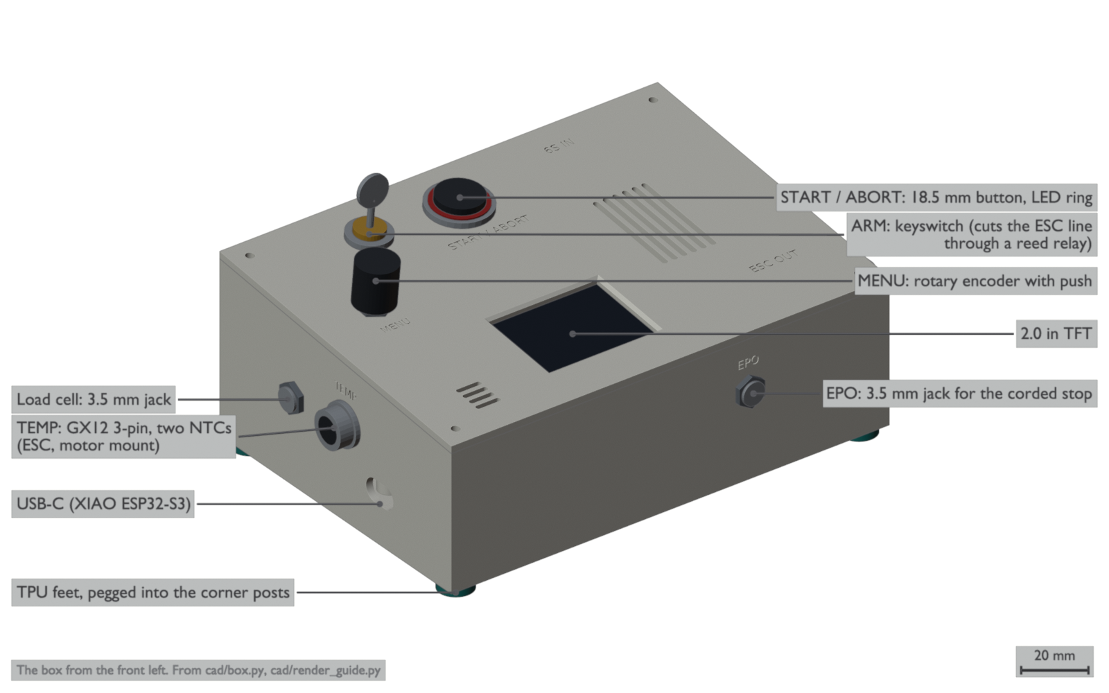
Section titled “The measurement box”The pack’s power goes through the box. A shunt in the positive line lets the box measure the current itself, and the box also reads the load cell and drives the ESC. A phone shows the readings through the box’s own web page, and a small display on the lid shows them at the bench.
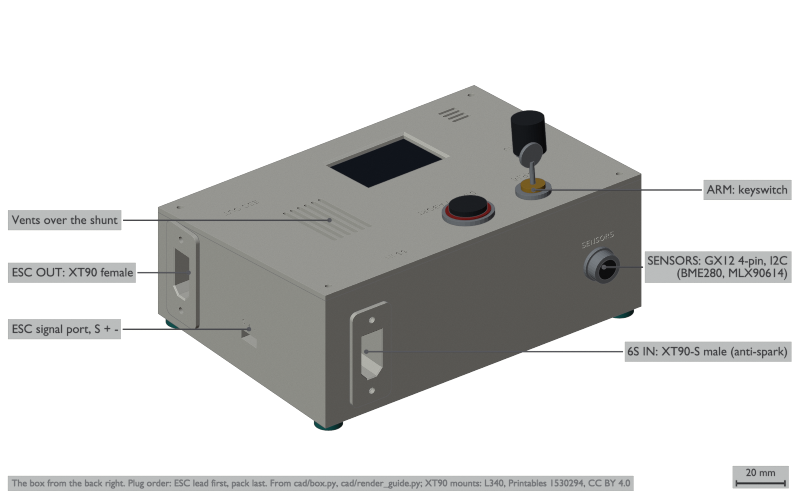
The box tub is not final: it waits on the insert coupon’s result. A render of the whole stand follows.
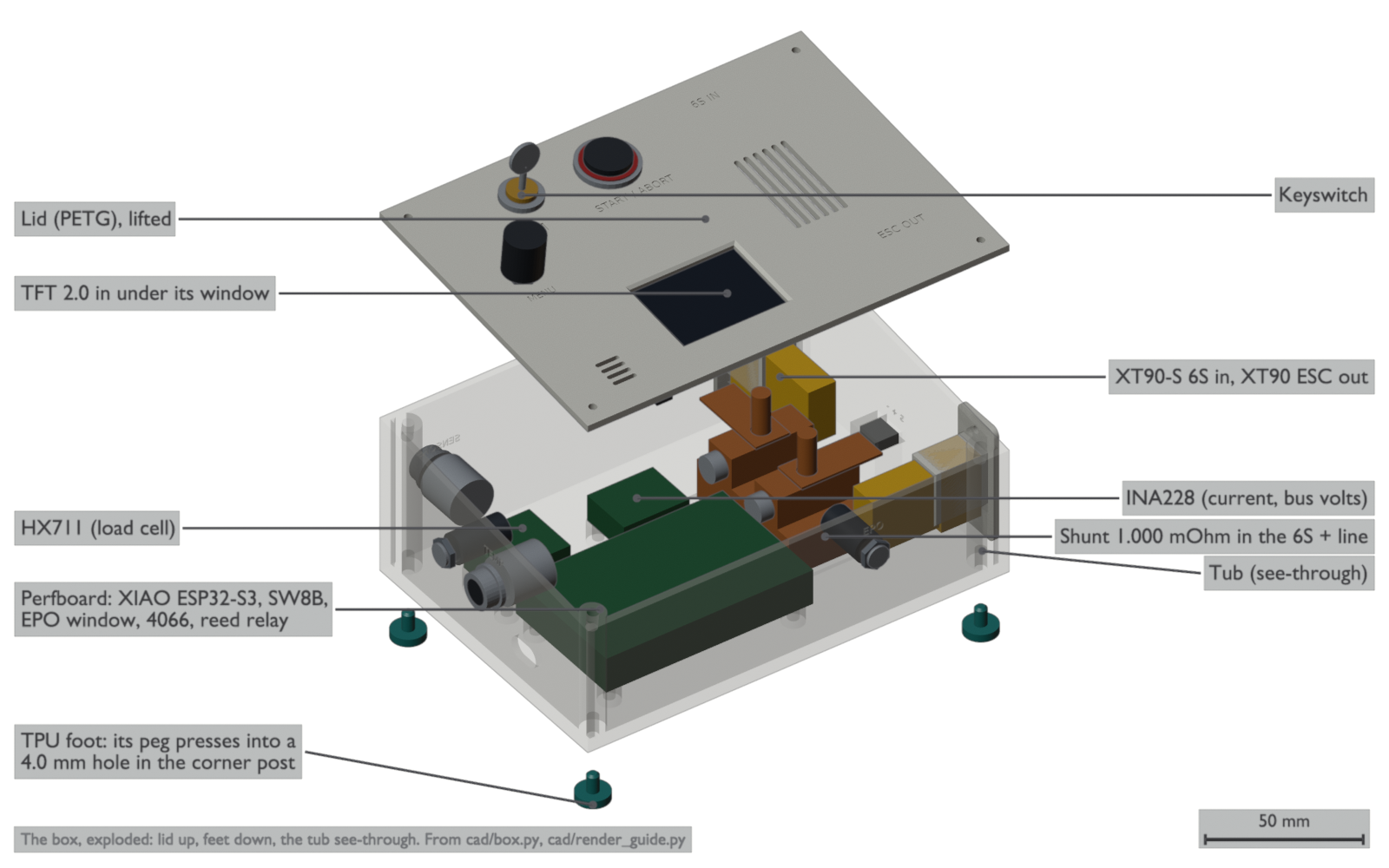
| Function | Part | Notes |
|---|---|---|
| Controller | Seeed XIAO ESP32-S3 | The box’s own board. The XIAO boards in row 16 are for the aircraft. The USB-C port is open through the wall |
| Load cell amplifier | HX711 at 80 samples a second | The box is drawn around the Adafruit 5974, which has a 10/80 switch. The listing photos of Ryan’s board (XFW-HX711) show 10/80 Hz pads. This is not yet checked on his board |
| Current and voltage | INA228 on a 1.000 mΩ shunt (Bourns RSA-100-100, ±0.25 %) in the positive line | The onboard shunt is removed, and a twisted Kelvin pair goes from the shunt’s sense screws to the INA228. On the positive side, the ESC and the controller have the same ground. 1 mV is 1 A |
| Display | AITRIP 2.0 in colour TFT module, 240 x 320, ST7789V, on SPI, with its own backlight resistor (Ryan’s own modules, chosen 2026-10-18 in place of the 2.42 in OLED; th-main c772def7) | On the lid. Its mount waits for Ryan’s measurement of a module |
| I/O coprocessor | Serial Wombat SW8B on the I2C bus | It drives the buzzer and the button’s ring light, so that the XIAO has pins for the TFT. The keyswitch and the abort button stay on the XIAO’s own pins. A fault on the I2C bus during a test aborts the test |
| Logic power | 5 V switching regulator, 9 to 72 V in, on a fused tap from the 10 AWG line, with a TVS diode after the fuse | The 72 V input is above the voltage spikes that the Lucid’s brake can put on the bus |
| Power path | XT90-S male (anti-spark) in, on the back wall; the shunt; XT90 female out, on the right wall; 10 AWG | Each XT90 is in an XT90 Panel Mount Unisex (L340, CC BY 4.0), with 2 x M3 x 10 and nuts |
| ESC signal | DShot, with PWM as an alternative | DShot is how the flight controller drives the Lucid. Bidirectional DShot also gives the rpm |
| Controls | Ryan’s own keyswitch to arm, his 18.5 mm start and abort button with a ring light, and a buzzer. A reed relay (Standex SIL05-1A72-71D) is a second cut in the ESC line | The keyswitch replaces the flip-covered toggle switch. The reed relay’s coil and pinout are estimates (th-eda with thrust-stand-21) |
| Emergency stop | An IDEC XA1E-BV302-R e-stop in a Bud HP-3651-B pendant, on 2.1 m (7 ft) of 24 AWG 2-core cable through an M12 gland. A window comparator (MCP6547, with a TLV3402 as the backup) and an SN74HC4066 switch read the loop | A corded stop in a hand-held pendant (th-eda with thrust-stand-21) |
| Encoder | Bourns PEC11R-4220F-S0024 with a Davies 1230-J knob | th-eda with thrust-stand-21 |
| Sensors | An ADS1115 breakout (Adafruit 1085) for two NTC thermistors and the 3V3 rail, an MLX90614ESF-BCF 10° infrared thermometer for the motor bell, a BME280 breakout (Adafruit 2652), and three TDK B57861S 10k NTCs (two used, one spare) | On two GX12 connectors with different pin counts, 4-pin SENSORS and 3-pin TEMP, so the leads cannot be swapped (th-eda, 2026-10-19) |
The XT90 connectors are rated 45 A continuous (Amass). The 49 A lift motor tests last only a few seconds.
Safety design
Section titled “Safety design”Thrust stand safety design gives the reasons for these rules and shows the two cuts in the ESC line.
These rules come before the firmware. The original sketch sent mid throttle at power-on, swept the full throttle range, and did not stop the motor when a test was aborted. The new box does not do these things.
- The ESC signal is zero throttle from power-on until the box is armed. The box sends no signal before the ESC pin is set up.
- Each test profile has a duty cap: 0.82 for the 3-blade lift prop. The output layer applies the cap, not the sweep logic.
- At 49 A (lift) or 44 A (pusher), the INA228 alert cuts the throttle to zero in an interrupt. The trip is set in the INA228’s own register, so it does not wait for the main loop.
- The button, the keyswitch, the phone page, and a lost phone connection during a test each stop the test at zero throttle.
- The keyswitch is the hardware arm interlock, with a reed relay as a second cut in the ESC line. The controller reads the key’s position through an 18k and 33k divider. th-eda is drawing this circuit (2026-10-18), and the full interlock rule follows when it is done.
After the interlock cuts the signal, the ESC needs a period at zero throttle before it arms again. Check this on the bench.
The bench layout has two rules of its own:
- Keep the box, the operator, the emergency stop pendant and the pack out of a band 30° either side of the prop’s plane of rotation, measured from the hub. A blade that comes off leaves in that plane. The 30° is our own conservative choice, not a figure from a published standard. The box as drawn is about 35° out of the plane, 192 mm along the motor axis (thrust-stand, 2026-10-19).
- Set the prop so that its wash blows away from the pillar and the box.
The ESCs
Section titled “The ESCs”The stand uses the flight ESCs: the TBS Lucid 4-in-1 for a lift motor (row 2b), and the DYS Aria for the pusher (row 5). Record the AM32 settings of each ESC before you change them for the bench. Restore them before the ESC goes back in the aircraft.
Print jobs
Section titled “Print jobs”th-main sliced these jobs on the Core One with the HF0.4 nozzle, in PETG. A G-code file is correct only for the STL it was sliced from: if a part changes, it is sliced again.
| Part | Time | Mass |
|---|---|---|
| Heat-set insert coupon (print first, after the printer repair) | 14 min 29 s | 4.95 g |
| XT90 Panel Mount x 2 (L340, plain), flange down, 0.3 mm layers | 18 min 16 s | 8.46 g |
| Motor bracket, motor face down | 46 min 43 s | 17.11 g |
| Pillar, square-nut base, flat, 0.28 mm layers, no supports | 1 h 14 min 57 s | 50.19 g |
| Box lid, top face down | To be sliced again after the lid redraw | |
| Box tub, floor down, no supports | To be sliced again after the lid redraw |
The jobs print in the order of the table. The insert coupon and the XT90 mounts print first, then the bracket. Before the pillar prints, examine the bracket’s slots and centre hole for a layer shift, and record the height at which any shift starts.
After printing, drill through the pillar’s six horizontal holes (two for the load cell, four for the base) so that the bolts go in. Use a 4.2 to 4.3 mm drill (M4).
Credits
Section titled “Credits”| Work | Author | Licence | Use here |
|---|---|---|---|
| Automated Thrust Testing Stand Powered by Arduino (Printables 764679) | niklasm | CC BY-SA 4.0 (the sketch’s own header says CC BY-NC 4.0) | The motor bracket and the pillar, changed as above. The Arduino box and the sketch are not used |
| XT90 Panel Mount Unisex (Printables 1530294) | L340 | CC BY 4.0 | Printed without changes, two off |
| The measurement box | thrust-stand-64 (CAD), th-eda (electronics) | CC BY-SA 4.0, the same as the stand (Ryan, 2026-10-12) | The box on this page |
Comments
Comment on the whole page here, or on one section or step with the button beside it.