
Antennas
Where the five radios on the TerraHawk put their antennas, and how to prove each link works on the bench before the maiden flight. Positions are in the kit’s assembly frame: Y is millimetres aft of the nose datum, X across the span, Z up. First planned 2026-09-26 from the STLs. Updated 2026-09-28 for the ELRS and telemetry antennas in the keels, and 2026-10-03 for the Q43 under the radome of Fuselage Mid B.
NOTE: Fuselage C v2.4B is the first build. The figures on this page are drawn on C v2.4B (th-blender W74b), but much of the text still describes Fuselage B. The C positions are agreed in
docs/agent-threads/fuselage-c/anddocs/agent-threads/gps/: the Q43 at (0, 300, 26.7) over the spars on a copper floor, with its compass off; the flight compass is the M10-25Q’s QMC5883L at (-3, 409, 43); the ELRS receiver at (0, 331, 13); LoRa B straight in through the starboard wire mouth to its plug and 50 ohm load. The text moves to C when th-main’s measured C coax lengths are ready. Do not cut coax from the lengths on this page for Fuselage C.
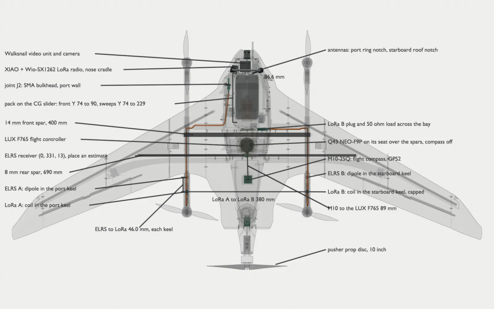
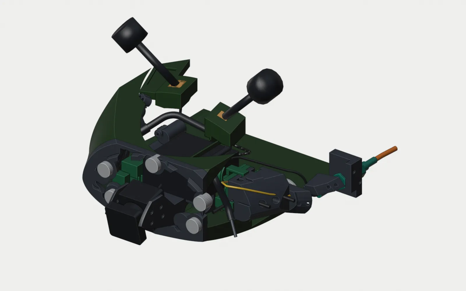
The plan in top view is docs/images/antenna-plan.png, drawn from th-blender’s Fuselage C v2.4B scene
(9b037f8d, redrawn for W127 in d2c1a009). It shows the Walksnail’s two antennas, the port one in the nose-ring
notch and the starboard one in the nose-roof notch, the LoRa radio in the nose cradle, joint J2, both
keel cassettes with an ELRS dipole and a LoRa coil each, the Q43 on its seat over the spars, the M10-25Q (the
flight compass and GPS2), the ELRS receiver, the LUX F765, and the pack on the CG slider. Its dimensions are
measured from the geometry: the two LoRa coils 380 mm apart, the ELRS dipole 46 mm from the LoRa coil in
each keel, and the two video antenna heads 86.6 mm apart.
The radios
Section titled “The radios”| System | Band | Aircraft end | Job |
|---|---|---|---|
| RTK GPS (Waveshare Q43 NEO-F9P) | GPS L1 1,575.42 MHz and L5 1,176.45 MHz, plus Galileo E1/E5a, BDS B1I/B1C/B2a, GLONASS G1 and QZSS; receive only | L1/L5 helical antenna and QMC5883P compass in one dome | Position, and RTK precision for landing and mapping |
| Walksnail Avatar HD Moonlight (Ryan, 2026-10-06; was the DJI O4) | 5.725 to 5.850 GHz | Two Avatar V2 antennas, LHCP, 1.9 dBi: one in the port nose-ring notch, one in a notch in the nose roof (th-blender W127) | Video to the goggles |
| ExpressLRS (a 2.4 GHz ELRS receiver on the RP4TD’s keel feeds; the RadioMaster Nomad module on the handset, Ryan, 2026-10-06) | 2.4 GHz only (see the band rule below) | Two vertical half-wave dipoles, one in each keel, true diversity | Control, plus MAVLink telemetry |
| Telemetry radio (SX1262 LoRa pair, replaces the SiK V3; Ryan, 2026-10-04) | 915 to 928 MHz | Two helically loaded dipoles, one in each keel, receive diversity on one two-radio board (Ryan, 2026-10-06). A single-radio unit uses the port coil only | RTK corrections from the hangar |
| Beacon board’s ESP32-S3 (WROOM-1U with a U.FL; th-eda, EDA c267f44, 2026-10-08) | 2.4 GHz: Bluetooth LE advertising on channels 37 and 38 (2402 and 2426 MHz) only | A Molex 204281 flex dipole, 35 x 11 mm, 1.8 dBi, 150 mm lead (Molex 2042810150; th-eda, EDA 3a353d6), along Y on the inner face of Fuselage C’s bay roof at X 0, centred at Y 385 (element Y 367.5 to 402.5; th-blender, limited by the lead length) | Lost mode only: a phone finds the aircraft on the ground. It never transmits while the aircraft can fly (see below) |
The Q43 replaces the Holybro H-RTK F9P Ultralight (L1/L2) that this page first planned for
(Ryan, 2026-09-28). It contains a u-blox NEO-F9P-15B receiver. The dome is Ø47.04 x 37.00 mm and
24 g (Waveshare Q43 documentation,
product page). The telemetry radio is a
Semtech SX1262 LoRa module, running our own mLRS target (MAVLink, not Meshtastic). The single-radio
unit is the Seeed XIAO ESP32-S3 with the Wio-SX1262 (SKU 102010611). The two-radio unit is th-eda’s
beacon board, with two Seeed Wio-SX1262 modules (the module that the XIAO kit uses: SX1262 with TCXO, the antenna
switch inside, IPEX on the module) in diversity (th-eda, EDA 99ed160, 2026-10-07). It carries MAVLink, the RTK corrections
from the hangar base and SITE_CLR. Radio A uses the 915 MHz coil in the port keel that the SiK V3
used, and radio B uses its mirror in the starboard keel. The link
margins on this page used the SiK V3’s -105 dBm at 64 kbps
(Holybro); a LoRa mode is more sensitive,
so they are on the safe side until the firmware’s mode is set.
What blocks radio on this airframe
Section titled “What blocks radio on this airframe”The printed airframe, lightweight PLA and PETG, is transparent to all four bands. These are not:
- Carbon. The 14 mm front spar crosses the fuselage at Y = 268 (400 mm long), the 8 mm rear spar at Y = 333 (690 mm long), and the two 14 mm VTOL spars run fore and aft at X = ±190. Carbon conducts and shadows radio, and an antenna lying parallel and close to a spar is detuned by it. The keel cores under the VTOL spars are glass fibre, not carbon, so that the keel antennas can work (th-aeronautics approved).
- The battery. The pack sits at Y = 100 to 250 and is a solid block of metal. The P50B pack is steel-can cells.
- Motors, ESCs and power wiring. They put out broadband noise, and the compass needs distance from their current. The DShot and motor leads run inside the VTOL spars, above the keels.
Two consequences shape the plan. When the aircraft flies away from you, anything in the nose looks back through the battery. When it flies toward you, anything in the tail looks forward through the H-frame and the battery. So each link needs a line of sight that clears the metal, and the two ELRS antennas must not both sit behind the same obstruction.
Placement
Section titled “Placement”The split: GNSS on top, air-to-ground links below. The GNSS antenna is on top of the aircraft and looks up at the sky. The ELRS and telemetry antennas are in the keels, below the fuselage, and look down and at the horizon. For these ground links, the important value is the worst-azimuth gain for vertical polarisation from 0 to -20 degrees of elevation. All long-range links are in that belt: 2 km at 120 m altitude is 3.4 degrees down. Straight down is always the shortest link, so it has margin even in the null of a vertical antenna.
RTK GPS: the Q43 dome under the radome of the spine, dome axis at X = 0, Y = 404. Ryan chose Fuselage B with the spine (2026-09-30, th-blender b254b0e): Fuselage Mid B and Tail B replace the kit’s Fuselage Mid, rear hatch halves and Tail Pusher. Since th-blender’s 505f241 there is no aft hatch: the top of the fuselage and the radome over the Q43 are part of Fuselage Mid B. Our GPS Saddle and the Hatch Rear (GPS hole) are no longer used. The geometry is under review until th-blender sends printable parts.
The dome is sunk 15 mm: its base is at Z = 22.0 and its top at Z = 59.0 (the radome follows the real Q43 profile, top about Z = 58.7 in 505f241), about 22 mm above the
local skin. A flat radome of 1.5 mm PLA covers it, with 2.0 mm of air above the dome and around its
sides. At L-band this costs a fraction of a dB (estimate). The rim of the recess is below the
antenna’s horizon, so it does not block low satellites. Key the dome with its connector forward,
toward the FC. Use only nylon or brass screws near the dome, because the compass is in the dome.
Measure the insert radius, thread and plain-hole radius of the real Q43 before the mount is printed.
The Q43 connects directly to the flight controller’s GPS port (SERIAL3, with I2C3 for its compass; the
Lumenier LUX F765 since th-avionics’ 3c9f3f6), with no DroneCAN node (th-avionics,
ccad706). The dome is about 330 mm from the video antennas.
Video: in the nose, one antenna in the port nose-ring notch and one on the nose roof. The Walksnail Avatar HD Moonlight (Ryan, 2026-10-06) has two antennas: Avatar V2, LHCP, 1.9 dBi, IPEX-1, listed as “R15 x 45 mm” without the cable (RaceDayQuads). Measured by Ryan (2026-10-20): 55 mm of flexible lead from the connector’s centre to a semi-rigid stem about 30 mm long, then a head about 11 mm tall and 15 mm in diameter. Both u.FL sockets are at the VTX’s back edge, and both leads leave through the window in its back wall (Walksnail’s STEP, th-blender W123). On Fuselage C (th-blender W127, e0006164; Ryan, 2026-10-21):
| Antenna | Station | Notes |
|---|---|---|
| Port | The nose-ring notch, X 15.10 to 22.96, Y 61.17 to 66.18 | A curved grommet hole (W123): the stem enters vertical, then turns outboard |
| Starboard | A notch in the nose roof centred at X -18, Y 74, aft of the static lines’ crossing | The hole is vertical at entry, then turns at 6.8 mm radius to 45 degrees outboard, raked 20 degrees forward so that the Hatch lifts straight off. Head centre (-42.5, 65.1, 67.3) |
The heads are 86.6 mm apart (1.7 wavelengths at 5.8 GHz). One is low on the port side and one is high on the starboard side, so in a bank the fuselage blocks only one of them. Each notch takes a TPU Antenna Slot Grommet (th-main, g14). Keep metal 10 mm or more from each antenna: the pitot’s metal tube is about 38.7 mm from the port stem (th-blender W93.2) and 42.2 mm from the starboard head. Both heads are outside the camera’s frame.
Each antenna’s own u.FL lead goes to the VTX on the Camera Arm, with no joint in the lead (at 5.8 GHz, 1.13 mm coax loses about 6 dB per metre, estimate). Do not bend a lead tighter than 6.8 mm radius. Do not bend the semi-rigid stem. The starboard lead passes the pitot’s static line and its coupler: it must not press on either, because that gives a wrong airspeed. Tie it so that it cannot rub. The VTX’s power and UART harness leaves the same back window in its own lane: it crosses each antenna lead once and does not run beside it. The goggles’ antennas must also be LHCP. The nose is as far from the GPS as the aircraft allows. The DJI O4 that this paragraph first described used one 80 mm antenna in either notch.
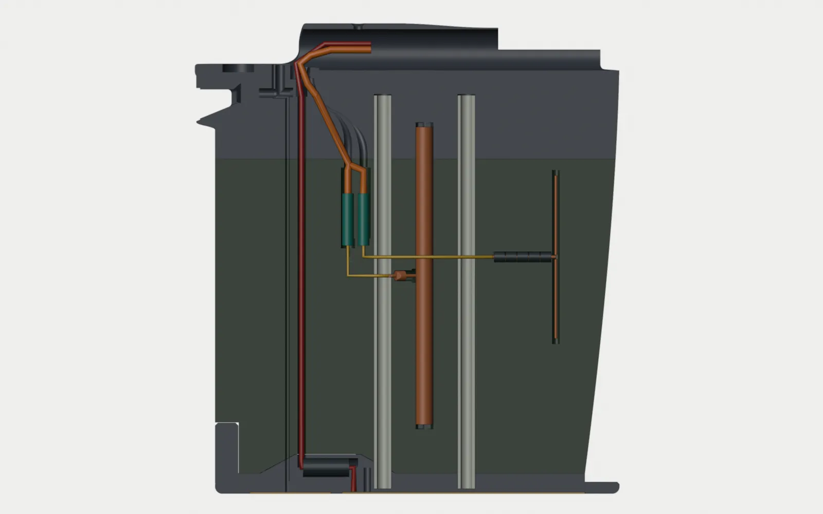
ELRS: receiver on the Avionics Plate, one vertical dipole in each keel. Each antenna is a half-wave dipole, 56.4 mm long, tuned in the NEC2 keel model. It is in a slide-in cassette (Ryan, 2026-09-27) in the keel at X = ±190, so the pair is 380 mm apart. Put each element between Z = -55 and Z = -117, forward of Y = 470, and 20 mm or more above the sole. The top limit keeps the element clear of the carbon VTOL spar. The bottom limit keeps it clear of the ground and the dock’s pin carrier.
On keel B the charge lead has its own channel at Y = 490, aft of the antennas. Both dipoles are
vertical. The first plan tilted one dipole 45 degrees. NEC2 showed that the tilt puts nulls down to
-10.3 dBi in the 0 to -20 degree belt. The vertical dipole gives +2.0 dBi at the horizon and -2.3 dBi
at worst in that belt (gnss/nec/airframe-antennas.csv, cases F1 and F2). The 380 mm of spatial
diversity does the work that the tilt was for (th-avionics, 2026-09-27).
Put ELRS B in the port keel at Y = 395 to 410, and ELRS A at the same Y in the starboard keel.
The receiver sits near the centreline on the Avionics Plate, at about X = -31, Y = 313. The
aircraft RG316 runs end at an MMCX plug under each keel root exit (th-blender’s cassette draft,
c82a475; on keel B the jacks are at Y = 468.6 for ELRS and 474 for LoRa, th-blender aee5d42 and 9e1eeeb). Cut ELRS B (port) to 498.8 mm and ELRS A (starboard) to 494.5 mm, from the SMA brackets on the Spar Box walls on Fuselage C (th-blender W121, 08799381; th-main f61130ec; estimates). The two runs
do not have to be equal. Keep the two cables of a pair within 0.3 dB of each other, which is about 210 mm of RG316
at 2.44 GHz, and do not add coax only to make them equal (GPS thread, ace46c7). On Fuselage C each
receiver pigtail (Taoglas CAB.011, 1.13 mm) goes from the RP4TD’s u.FL to its SMA bracket on the Spar Box wall
(th-blender W121). Do not bend it tighter than 6.8 mm. Its spare length lies in a hairpin (port) or a straight run
(starboard), not in a loop. Tie each pigtail to its tie bar on the Bay wall (th-blender W122, 6377d401). Use waxed
lacing with a surgeon’s knot under the pad. If you use a zip tie, close it by hand until it is snug, never with a
tensioning tool: the coax must still turn in the tie, because a tight tie crushes the dielectric. Each cassette adds a 1.13 mm pigtail: on keel B, 74 mm for ELRS and 37 mm for the telemetry radio. The
total ELRS B feed loss at 2.4 GHz is about 1.9 dB (estimate): about 0.8 dB of RG316, 0.3 dB of
cassette pigtail, 0.5 dB for the receiver’s u.FL-to-SMA pigtail and its u.FL, and 0.35 dB for the MMCX and SMA pairs. The cut
lengths of record are in docs/agent-threads/harness/ (th-main). They change when the bay layout
changes.
Telemetry: radio in the nose, a helically loaded dipole in each keel. A straight
915 MHz half-wave dipole is about 153 mm long, more than the keel has room for. So each arm of the
dipole is a 6 mm coil of about 4.8 turns, centre fed, between Z = -41 and Z = -144. In the NEC2
model it resonates at 43 ohms, is 91 % efficient, and gives -0.5 dBi at worst in the 0 to -20 degree
belt (case C). It goes in a keel cassette, like the ELRS dipoles, at Y = 440 to 462. Since 2026-10-06 (Ryan),
each keel has one: LoRa A in the port keel with ELRS B, and LoRa B in the starboard keel with ELRS A.
The starboard cassette is a mirror of the port cassette. The results below are for the port keel.
They apply to the starboard keel by symmetry. In the NEC2 model of both keels together, the two coils couple at about -20 dB, and the envelope
correlation of their patterns is about 0.0001 at 921.5 MHz (tools/lora_diversity_nec.py,
gnss/nec/lora-diversity.txt, simulated, charge leads left out). So the two antennas fade
independently, which is what diversity needs. When one radio transmits at 20 dBm, about 0 dBm reaches
the other, which is below the SX1262’s +10 dBm limit and does not matter, because the two radios never
receive while one transmits. Only Y 416 to 426 and Y 440 to 462 give the 6 mm coil its space
(tools/antenna_fit.py). Do not use Y 416 to 426: there the coil is too near ELRS B.
With ELRS B at Y = 402 and the telemetry coil at Y = 451, the NEC2 model gives these results
(tools/keel_coupling_nec.py, gnss/nec/keel-coupling.csv, simulated):
| Item | Result |
|---|---|
| Coupling, telemetry to ELRS B, 915 to 928 MHz | -31 dB |
| Coupling, telemetry to ELRS B, 2400 to 2480 MHz | -24.5 dB |
| Change to each antenna in the 0 to -20 degree belt | 0.5 dB or less |
| Shift of the ELRS B resonance | +16 MHz |
The coil has a series resonance near 2,700 MHz, so at 2.4 GHz it is a weak parasitic element. Moving the coil to the front stilt gains only about 7 dB, because the carbon spar connects the two locations. So the telemetry coils stay in the keels.
Filters and chokes. At -31 dB, a telemetry transmission at 20 dBm puts about -13 dBm into the
ELRS port. An ELRS telemetry burst puts about -6 dBm into the telemetry radio’s port. Neither datasheet gives an
out-of-band blocking figure, and neither board documents a front-end filter. Damage is not likely
(the absolute maximum inputs are +10 dBm), but the receivers can lose sensitivity. The risk is
that the telemetry radio loses RTCM packets during ELRS telemetry. Do bench test 7 first. If it shows a loss,
put a 2.4 GHz band-pass filter in each ELRS coax and a 915 MHz low-pass or SAW filter in the telemetry
coax. Filters of about 30 dB give margins of about +23 dB and +16 dB (estimate). On keel B, put one ferrite
bead (Fair-Rite 2643250302, 43 material) on each keel charge lead, in its boss at the sole. Keel B has
no room for a bead at the lead’s top end: the blade is too thin, and the spar bore is full of the phase
leads and the RG316 runs. Without the top bead, the NEC model gives a worst belt gain 0.5 dB lower but a
mean belt gain 0.5 dB higher, with the same isolation (tools/keel_b_antennas_nec.py, cases
g-aee5d42-riser and g-9e1eeeb-A, simulated). So keel B uses the sole bead only. Put five 61-material beads (Fair-Rite 2661000101, 3.51 x 1.30 x 3.25 mm) on each ELRS
pigtail at the dipole feed, and one on each telemetry pigtail at the coil feed (one does the job of two in NEC2, cases
j-48030b7-1b and -2b, and leaves about 4.7 mm for the feed joint). Five short beads give about
the same choke as the three longer beads in the model. Without them, current on
the outside of the pigtail shield lowers the telemetry to ELRS isolation from -31 to -15 dB. It also
lowers the worst ELRS B belt gain to -9.3 dBi (tools/cassette_pigtail_nec.py, simulated). A
larger gap between the pigtail and the coil does not help. Tune the telemetry coil with the cassette, the
pigtail and the beads installed, because the pigtail lowers its resonance by 10 to 28 MHz. Without it, the lead lowers the telemetry belt gain from
-1.7 to -3.3 dBi in the model.
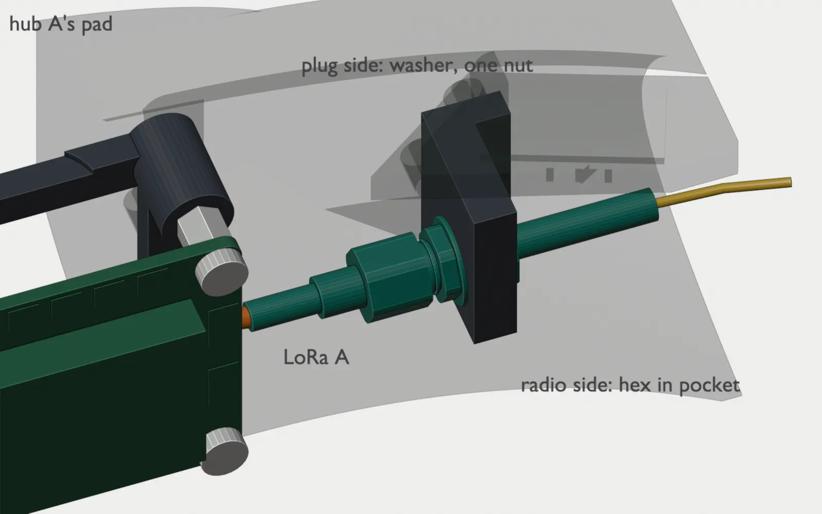
The radio sits in the nose, on the port wall at about X = 39, Y = 66 (th-blender, 1dbefba). A 95 mm u.FL to SMA pigtail with a rear-mount bulkhead jack, the Taoglas CAB.011 (row 16e; Ryan, 2026-10-07: the jack’s thread goes through the bracket from the radio side, and its washer and nut go on from the plug side) goes from its u.FL to the SMA bulkhead of joint J2 on the port bay wall at Y = 118 to 120.5 (th-blender, a89d83b). From there the RG316 run to the port keel is 602 mm: along the port wall past hub A, over the front spar and into the port channel mouth. That is an estimate measured from the back of the SMA plug (th-main, 7648067; cut lengths of record: docs/agent-threads/harness/).
The antenna is no longer on the tail top, so it is no longer 110 mm from the GPS. It is now below
and outboard of the GPS, about 250 mm away (estimate from the positions). Set the telemetry radios to hop
only from 915 to 928 MHz. Meshtastic stays on a fixed
channel below 915 MHz, on the ground only.
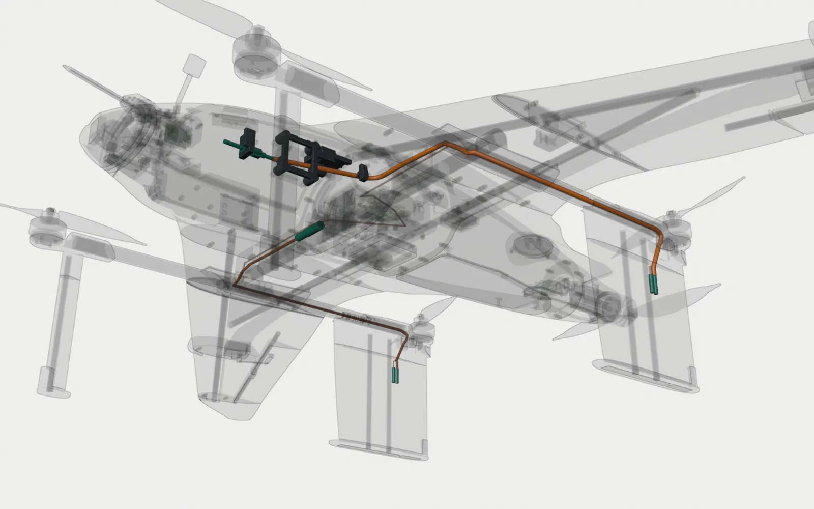
Coax route: through the kit’s wire channel and the VTOL spar. Each coax goes from its radio or its
park to the wire channel’s mouth on its own side of the bay, at Y = 283 to 308 and X = about ±62, beside the
lift ESC. It enters at the mouth’s forward upper corner, outboard of and above the phase leads, and crosses them
at a right angle; a snap clip holds it at the mouth (th-blender, d7906f8). The kit’s 25 x 10 mm channel takes it
outboard and up a ramp to the VTOL spar’s wire slot at about Y = 295, then aft inside the spar to its rear tip
at Y = 486, and down into the keel (tools/wire_routes.py --keel-coax, th-main 7648067). The phase leads
share the channel and the spar with the coax. Put a ferrite on each coax near the radio as a common-mode
choke. There is no exit hole at Y = 208: that position is the wing spar’s bore. Do not drill there.
The carbon spar is a shield for the cable. Never use it as an antenna location. In NEC2 a helix wound around the spar is 40 % efficient at 3 ohms (case D).
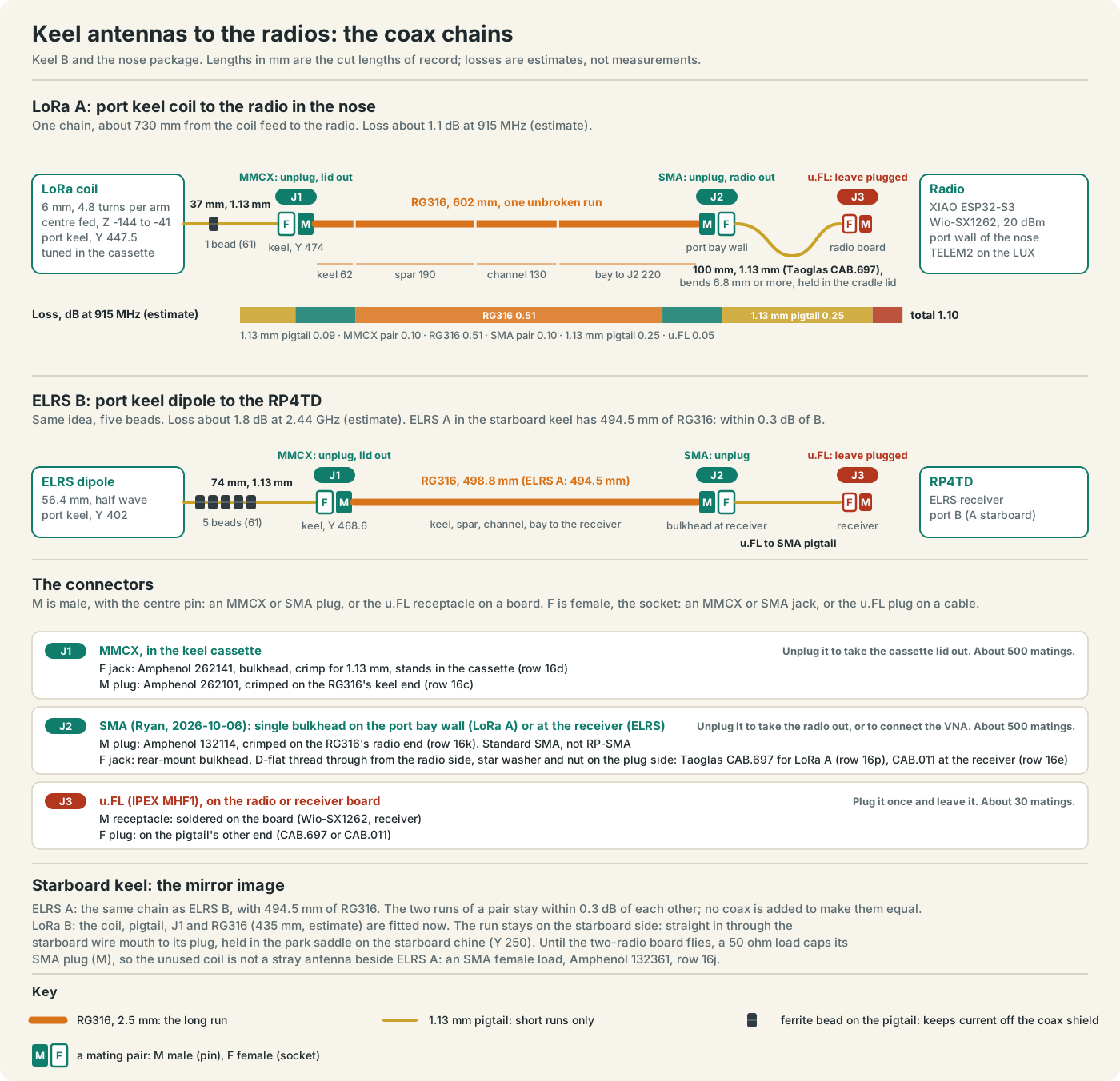
The chain, from each keel antenna to its radio. Each keel antenna connects to its radio through
three joints. J1 is an MMCX joint in the keel cassette: unplug it to take the lid out. J2 is an SMA
joint at the radio end (Ryan, 2026-10-06): the male plug on the RG316 screws onto a female bulkhead
jack in a printed bracket: on the port bay wall at Y = 118 to 120.5 for the LoRa radio (th-blender, a89d83b), and beside the ELRS receiver. Unplug it to
take the radio out, or to connect the VNA or an inline filter. Use standard SMA, not RP-SMA, and
tighten it by hand and then with a wrench to about 0.6 N·m, so it does not loosen with vibration.
The jack’s thread has a flat that fits the bracket’s D-shaped hole, so the jack cannot turn while you
tighten its nut or the plug. Put the star washer under the nut on the plug side. If the jack turns, it
twists the pigtail behind it and pulls on the u.FL. J3 is the
u.FL on the radio board: plug it once and do not unplug it again, because a u.FL is good for about 30
matings. The diagram gives each joint’s male (M) and female (F) half and its parts list row, each
cable’s length, and the estimated loss: about 1.1 dB for LoRa A and about 1.9 dB for ELRS B
(tools/antenna_chain_svg.py). The keel B cassette in detail, with its parts, lid and positions, is on
Landing gear, “Antenna cassette”.
The chain with the two-radio beacon board (later). The chain above is for the first build, with the single radio in the nose. The two-radio beacon board goes flat in the belly between the spars, when the lift ESCs move to the motors (Fuselage C or the pod ESCs, Ryan 2026-10-07). Then each radio gets its own J2: a single rear-mount SMA bulkhead on the spar-box side wall beside it, port for LoRa A and starboard for LoRa B (th-eda’s layout puts them at about Y 306 and Y 291.5), with a short u.FL to SMA pigtail to the radio. Each keel’s RG316 then ends on its own side, with no crossing. J1, J3 and the keel cassettes do not change.
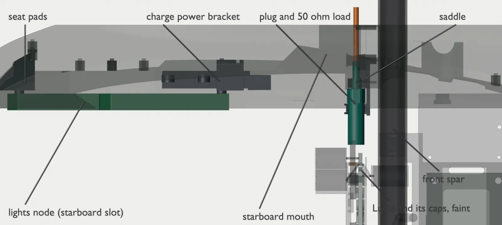
The starboard LoRa run in the first build. Each LoRa run stays on its own side (Ryan, 2026-10-09). The port run ends on a single-jack J2 bracket on the port bay wall (th-blender, 363f399). The starboard run (LoRa B) is fitted now, because the VTOL spar is 90 to 98 % full with the phase leads and a coax cannot be pulled in later (th-main). It leaves the starboard channel mouth at its aft upper corner, crosses over the phase leads at a right angle with 8.3 mm of clearance, and goes into a cradle on the Fuselage Front’s starboard wall over the front spar, at X -58, Z 17, Y 241 to 281 (th-blender, 63fa640). The plug points forward. Its SMA plug (M) carries a 50 ohm load (Amphenol 132361, row 16j) until the two-radio board flies, so the unused coil is not a stray antenna beside ELRS A. The plug and load are 135 mm from the Q43’s base, more than the 100 mm that the compass needs; tie them at both ends so they cannot move.
When the two-radio board comes to Fuselage B, put its starboard J2 bulkhead at this parked plug, not the plug at the jack. The board reaches its J2 through a 95 mm pigtail, so the jack can go anywhere near the plug, but the coax cannot be made longer through the full spar. Fuselage C’s jack station does not apply to Fuselage B.
Cut lengths (estimates): LoRa A 602 mm, LoRa B 435 mm (th-main, 7648067), ELRS B 498.8 mm, ELRS A 494.5 mm (th-main f61130ec, from th-blender W121). Each pair is well inside the 0.3 dB that a pair may differ (ace46c7): the LoRa runs differ by about 0.14 dB at 915 MHz and the ELRS runs by about 0.01 dB at 2.44 GHz. Crimp the MMCX plug on the keel end last, at the cassette, and trim any extra coax there. Do not bend the coax tighter than a 13 mm radius.
Fit check
Section titled “Fit check”tools/antenna_fit.py models each radio from its datasheet, and the RTK GPS from Holybro’s STEP
file, then places it in the assembly with the Survey3 fitted and measures the gap to every part near
it, including the carbon spars and the 6S2P battery. It searches for positions where the plan leaves
a choice and requires at least 2 mm of air. It checks each item alone.
tools/antenna_fit.py was updated for the Q43 and the keels (th-main, 2026-09-28). It scans the
port keel shell (the starboard keel is its mirror). It keeps 0.8 mm of shell on each side and
1.0 mm to the glass cores, the spar saddle and the motor-mount root.
| Item | Where it fits | Tightest gap |
|---|---|---|
| Q43 dome | Under the spine radome, sunk 15 mm, top Z = 59.0 (b254b0e) | 2.0 mm air gap to the radome |
| ELRS dipole (2.5 mm, Z -114 to -58) | Y 392 to 427, 439 to 469, 499 to 513 | 0.8 mm of shell |
| telemetry coil (6 mm, Z -144 to -41) | Y 416 to 426, 440 to 462 | Only where the shell is 8 mm thick |
| O4 antenna | Port notch in the nose ring, X = 15 to 21, Y = 67.2 to 71.7. The ring is part of the fixed Fuselage Front, so the antenna stays on when the short cone comes off. The grommet is a 0.1 mm press fit in the notch (th-blender, 7bcbbd8) | Lead to the O4 Air Unit Cradle: 3.1 mm. Antenna to the LoRa radio’s lid: 11.1 mm. No overlaps |
The cassette is not in the fit check. A 6 mm coil in the 8 mm keel leaves 1 mm on each side, so the cassette walls must be thin.
Aft bay interior on the centreline, measured by casting rays inside the skin:
| Station | Height | Width |
|---|---|---|
| Y = 400 | 37 mm | 129 mm |
| Y = 420 | 31 mm | 113 mm |
| Y = 440 | 33 mm | 99 mm |
| Y = 460 | 13 mm | 20 mm |
| Y = 520 | 24 mm | 80 mm |
Datasheet sizes: ELRS RP4TD 23.7 x 16.3 x 4 mm with two 65 mm T antennas; telemetry radio about 23 x 22 x 8 mm (placeholder until the board is chosen); DJI O4 Air Unit 30 x 30 x 6 mm with one 80 mm antenna. The keel dipoles replace the RP4TD’s T antennas and the telemetry radio’s stock antenna.
Options
Section titled “Options”ELRS antennas in the winglet fins. Not chosen: the keels give 380 mm of vertical diversity below the fuselage. Each winglet stabilizer is a vertical fin 64 mm tall, almost a half wave at 2.4 GHz. The fins are 1.48 m apart, but each lead is about 0.75 m through a wing and must break at the quick-release joint with a small RF connector.
Two RTK GPS antennas at the wingtips, for heading. Not planned. ArduPilot can take yaw from two F9P-class receivers, one as a moving base, instead of from the compass. With the Q43 this means a second Q43 or another F9P, and a data link between the two receivers. Waveshare’s pinout marks the Q43’s second UART pins as reserved, so this link is not confirmed.
The dome is 37 mm tall and the wing is about 15 mm thick at the tip, so each dome needs a pod. The
quick-release wings must seat the
same way every time, on both airframes, because ArduPilot needs the separation to the millimetre
(GPS_POS1 and GPS_POS2).
Combining nose and wingtips into one array. The DJI O4 has one antenna port and the RP4TD two, and each radio can only choose between the antennas it has; neither can steer or combine more. A beam-forming array across the airframe would need a custom radio. The spatial diversity across the keels gets most of the benefit with parts that exist.
Interference to check for
Section titled “Interference to check for”- Video air unit into the GPS. Digital air units are a known source of noise near the GPS bands. The separation of about 330 mm is the main defence. If the bench test below shows it, fit a ferrite on the video unit’s power lead, keep its wiring away from the GPS cable, and try grounded copper tape on the air unit’s case.
- Telemetry and control transmitters into the GPS. Keep the telemetry and ELRS antennas 100 mm or more from the GPS. The keel antennas are below the fuselage and about 250 mm from the dome.
- Motor leads into the telemetry radio. The DShot and motor leads in the VTOL spar are above the keel. At 915 MHz their noise can reduce the telemetry radio’s receive margin, and the telemetry radio receives the RTCM. Do the telemetry test below with the lift motors on.
- ELRS in the LoRa band. The Nomad module has two LR1121 radios and can transmit at 915 MHz as well as 2.4 GHz, at up to 1 W. The 902 to 928 MHz band is the LoRa link’s. Use only 2.4 GHz ELRS modes: no 900 MHz modes and no Gemini Xrossband (Gemini-X). A Nomad at up to 1 W in the LoRa band near the dock would block the RTK corrections. The same rule applies to any dual-band ELRS receiver fitted later.
- The beacon’s 2.4 GHz radio and ELRS. The beacon board’s ESP32-S3 shares the 2.4 GHz band with ELRS, and no place in the fuselage isolates it from the keel dipoles. Because of this, the firmware keeps them apart in time (GPS thread, b0b2627 and 1dc1d55). With main power on, the radio is off while the flight controller is armed (
HEARTBEATbit 128) or silent (no heartbeat for 3 s or more, and at boot until the first heartbeat). With a disarmed heartbeat, it starts only on an explicit command, for the bench. In lost mode (main power gone and no flight controller heartbeat for 3 s or more; or the lights node’s flag for a flight controller silent 60 s after arming, but only when the beacon’s own GPS shows the aircraft stationary for 30 s; a loose 6S lead or a broken telemetry lead alone is not lost mode, GPS thread 20261011T174636Z and 20261011T174830Z), it sends Bluetooth LE advertising at 0 dBm, and at 10 dBm or less only if the range test needs it and the GPS noise test still passes, never at the same time as a LoRa transmit. It does not use channel 39 (2480 MHz): 2480 MHz minus the LoRa band is 1552 to 1578 MHz, which is in GPS L1 and BeiDou B1. At the dock, the radio never starts. Its antenna lies along Y, about 63 mm from the GPS dome’s axis, so the dome is in the dipole’s axial null. Keep it 25 mm or more from carbon, metal and the payload. - Survey3 Wi-Fi. Some Survey3 listings mention Wi-Fi. If yours has it, switch it off for flight, because it shares the band with ELRS.
- Compass. The compass is the QMC5883P in the Q43 dome, at the mast. Keep steel away from the dome: steel near the compass shifts its offsets. The dome mount uses nylon or brass screws for this reason.
ArduPilot settings
Section titled “ArduPilot settings”Tell the autopilot where each GPS antenna is relative to the body origin. RTK is precise to a few
centimetres, so a few centimetres of offset matter. The body origin is the design CG, (0, 270, -5.6), an
estimate; INS_POS1 uses the same origin. Offsets are in metres, X forward, Y right, Z down, from that
origin. These are the Fuselage C values (Q43 at Y = 300; the M10 at th-blender’s W52 station):
| Parameter | Value | Why |
|---|---|---|
GPS1_POS_X |
-0.030 | The Q43’s dome axis at Y = 300 is 30 mm aft of the origin at Y = 270 |
GPS1_POS_Y |
0 | On the centreline |
GPS1_POS_Z |
-0.057 | The phase centre is 57 mm above the origin (Z = -5.6), at Z = 51.4: the Q43 sits on the copper floor at Z = 26.7, and the phase centre is taken at 2/3 of the 37.0 mm dome (ESTIMATE, ±10 mm) |
GPS2_POS_X |
-0.140 | The M10-25Q (GPS2) at Y = 410, 140 mm aft of the origin (th-blender W52, 6ac8c58e) |
GPS2_POS_Y |
0.006 | 6 mm to starboard |
GPS2_POS_Z |
-0.052 | The patch face at Z = 46.4 |
The aircraft file and SITL’s SIM_GPS1_POS carry the same values (th-avionics and th-simulator,
7894390d). Change them together: a simulated antenna that differs from the autopilot’s offset moves
simulated dock landings. The Q43’s phase centre is a placeholder, because Waveshare publishes none. When a
measured value is available, replace it. For mapping, the Survey3 page’s antenna-to-lens offset uses the
same measurement. Fuselage B’s values were (-0.134, 0, -0.052), with the dome at Y = 404.
On Fuselage C the flight compass is the M10-25Q’s QMC5883L. The Q43’s compass is off for flight. The
compass offsets belong to the airframe, because the spars, the pack and the power wiring near the
compass are part of it. Do a full compass calibration on the assembled aircraft; COMPASS_ORIENT comes
from it. Its first-flight gate (M1 to M8: a surveyed RTK line, the loaded checks) is in
docs/agent-threads/gps/20261015T212251Z-th-telemetry-m10-sole-compass.md. Do not calibrate the compass
while a bench WiFi session on the beacon board is open. For
the GPS driver settings, refer to the RTK notes in docs/parts-list.md.
Bench tests before the first flight
Section titled “Bench tests before the first flight”With the props off:
- GPS noise. Get a fix outdoors with everything powered but no transmitters on. Log for two
minutes. Then turn on the video unit at full power, the ELRS receiver’s telemetry and the telemetry link, and
log again. Compare the
UBX1log message’sjamIndandnoisePerMS, the satellite count and HDOP, and whether the RTK fix holds. Anything that climbs when a transmitter comes on is getting into the GPS.- Do the same step with each of these on, one at a time: the lift motors at hover current (tied
down, props on), the video unit at full power, both LoRa radios transmitting, the beacon board
running, and the lights with the strobes flashing and the landing light on. Pass: the mean C/N0 is
down 2 dB or less on L1 and on L5, and the RTK fix holds.
UBX1logs only the L1 block, so also capture L5 and the per-satellite C/N0 with u-center through the flight controller’s passthrough during the same steps. Watch the GLONASS G1 signals with the beacon board running: one of the ESP32’s clocks has a weak harmonic at 1600 MHz. - If the noise rises, fit the copper shield under the dome (plain or tin-plated copper, never steel or nickel), and do the step again.
- Canopy coupons (Fuselage C;
tools/make_gnss_coupons.py, th-blender 2f60a72). Put the Q43 in the open sky. Log for 5 minutes with the bare dome, then 5 minutes with the coupon fitted, and then the same pair again (bare, coupon, bare, coupon). Log the LC29H base beside it as the sky reference. Compare the mean C/N0 of the satellites above 15 degrees between the bare and coupon blocks. Do this with the 1.5 mm PETG cup over the dome, then with the 7 mm LW-PLA panel 20 mm from the dome’s side, turned toward the lowest satellites. A difference under about 0.5 dB is too small to measure, so the result is “no clear loss” or “clearly worse”. Print the panel with the LW-PLA profile, as the fuselage wall is printed.
- Do the same step with each of these on, one at a time: the lift motors at hover current (tied
down, props on), the video unit at full power, both LoRa radios transmitting, the beacon board
running, and the lights with the strobes flashing and the landing light on. Pass: the mean C/N0 is
down 2 dB or less on L1 and on L5, and the RTK fix holds.
- RTK with the LC29H base. Put the Q43 and the LC29H base outdoors with a clear sky. Send the base’s RTCM to the aircraft over the telemetry radio pair. Make sure that the Q43 gets an RTK fixed solution and keeps it for ten minutes. This pair of receiver makes is not tested yet.
- ELRS range and diversity. Turn the transmitter down to its lowest power, walk 30 to 50 m away and have someone rotate the aircraft through a full turn, nose up and on each wing. Watch both antenna RSSI values. Neither should drop out at the same time as the other. Then do a check for noise from the lift motors. On Fuselage C each ELRS RG316 leaves its wing-root mouth beside that side’s lift phase bundle (th-blender W121, 08799381). Tie the aircraft down with the propellers fitted, and set the handset’s power or distance so that each ELRS RSSI is about 20 dB above the receiver’s sensitivity. Log both RSSI values for 30 s with the lift motors at hover current, then 30 s with them stopped, and then the same pair again (A-B-A-B). Each antenna’s mean RSSI with the motors running must be 2 dB or less below its value with them stopped.
- Video. Same walk, goggles on, aircraft tail toward you. That is the outbound attitude and the worst case for the nose antennas.
- Telemetry radio. Check local and remote RSSI in the GCS at the same distance, and that RTK
corrections keep arriving (
GPS_RTCM_DATA) with the aircraft at every attitude. Do this check again with the lift motors on, props still off. Then do a check for noise from the two Matek Power Hubs: the RG316 to the port keel runs behind hub A on the port bay wall (th-blender, 06be960), and hub B is on the starboard bay wall beside the starboard RG316 (th-avionics, eeea9fc). Do the check below once for each hub. Set the dock radio’s power or distance so that the link SNR inRADIO_STATUSis between 0 and +5 dB. Log the SNR for 1 minute with the hub on and loaded (hub A: the video at full power; hub B: one elevon held against a hand), then 1 minute with that hub’s battery lead unplugged, and then the same pair again (A-B-A-B). If the mean SNR with the hub on is more than 2 dB lower, move the coax away from the board or put a ferrite on the hub’s leads. Do the same check for the night lights, because each keel carries two strobe LEDs at Y = 492, about 41 mm aft of the LoRa coil (th-blender, 5e789f7), and each keel’s strobe pair shares the wire channel and the VTOL spar’s bore with that keel’s coax (th-telemetry, fuselage-c 20261018T081238Z). Log the LoRa SNR and the ELRS RSSI on both keels with the strobes flashing, the landing light on and the position lights at their night duty (LGT_POS_PCT33 %), against all lights off (A-B-A-B). The pass is the same: 2 dB or less, and no rise in RTCM packet loss. If it fails, check that the lights node’s common-mode chokes are fitted (th-eda, 7e7574c) and that the strobe pair has its type 43 bead at the keel entry. - Trough RSSI. Dock the aircraft in the hangar, with its keel antennas in the troughs. Log the telemetry and ELRS RSSI with the lid open. Close the lid and log the RSSI again. Record the margin for each case.
- telemetry and ELRS in one keel. Do test 3 at the far end of the walk, with the handset at reduced
power, so that ELRS is near its sensitivity limit. Do it once with the telemetry radio off and once with the
telemetry radio sending MAVLink at full rate. Then turn ELRS telemetry on and log the telemetry radio’s remote RSSI and the
RTCM packet loss. If ELRS loses more than 3 dB of range with the telemetry radio sending (th-avionics), or
the telemetry radio loses RTCM packets, fit the filters from the telemetry paragraph above. The bench filters are
in the test kit (
docs/parts-list.md). - Cassette tuning. Do this before tests 3 to 7. The tools are in
parts/, fromtools/make_coil_tools.py(th-blender, 6dc7468). Make the keel antennas gives these steps in full.- Print the Antenna Groove Coupons first (plate
petg-Antenna Groove Coupons, th-blender 68bc62c8). The D45 coupon has groove widths of 1.00 to 1.40 mm; the D55 coupon has a deeper groove at 1.10 and 1.20 mm. Wind the 20 AWG magnet wire along the D45 coupon, and push it sideways in each band with a fingernail. A band passes when the wire stays fully in the groove. In the narrowest band that passes, the wound diameter must be 6.2 mm or less. If no D45 band passes, do the same test on the D55 coupon. Do not print the formers yet: tell th-blender the coupon, the narrowest width that passes and the wound diameter, and th-blender sets the formers’ groove. - Make each ELRS dipole on the ELRS Dipole Gauge. Put the 18 AWG copper wire in each channel against the end stop, with the wire past the feed end. Bend it 90 degrees down over the shoulder (its end rides over the far edge of the step), then cut the tail flush with the floor of the step: about a 2.5 mm solder tail. The tail’s exact length does not matter, because the trim on the VNA corrects it. Each arm is then 29.4 mm from the bend to the tip, which includes 2 mm for trimming.
- Wind each LoRa coil on its LoRa Coil Former (grooved). Use the port former for the port keel and the starboard former for the starboard keel, because the turns go in opposite directions. Put the former in the winding cradle. Anchor the wire in one end slot, turn the thumbwheel and keep the wire in the groove through the wire guide until you reach the feed gap. Wind the second arm in the same way from the other end. Put the beads on the pigtail first, then put both wire ends through the 1.8 mm feed hole and solder them to the pigtail. The enamel melts when you solder.
- Install the elements, the pigtails and the ferrite beads in the lid, and screw the lid to the keel. Connect the NanoVNA to the MMCX jack under the root exit.
- Trim each ELRS dipole tip, 0.5 mm from each arm at a time, until S11 is -10 dB or lower from 2400 to 2480 MHz. Use the 1 mm marks on the gauge. Each 1 mm cut from both arms raises the resonance by about 80 MHz (estimate), and the first reading is about 2280 MHz (estimate).
- Trim the LoRa coil until S11 is -10 dB or lower from 915 to 928 MHz, with the lowest S11 between 910 and 935 MHz. Unwind one tick (a quarter turn) at the anchor end of each arm, the same on both arms, then measure again. The ticks are counted from each anchor end, so the feed joint does not move. One tick on both arms raises the resonance by about 45 to 50 MHz (NEC2, simulated), more than the band is wide, so make the last step half a tick (an eighth of a turn) on each arm. After each trim, cut the unwound wire off where it leaves the groove. Do not leave it standing off the former: it is still part of the antenna. The lid’s 6.2 mm groove holds the turns in place.
- The pigtail lowers the LoRa coil resonance by 10 to 28 MHz. Do not tune the coil without the pigtail and beads installed.
- Print the Antenna Groove Coupons first (plate
After the maiden flight, log the RSSI of both ELRS antennas in banked turns. This log shows whether the two vertical dipoles need a different angle.
Source: docs/antennas.md in the repo. Edit it there; this page is generated.
Comments
Comment on the whole page here, or on one section or step with the button beside it.