
Thrust stand safety design
Why the stand needs a safety design
Section titled “Why the stand needs a safety design”A thrust stand runs a motor at full power with nobody’s hands on anything, on purpose. TerraHawk’s lift motor, an EMAX ECO II 2807 with an 8 inch folding 3-blade prop, is expected to pull about 64 A uncapped on a fresh 6S pack. That is past both the motor’s 52 A peak and the ESC’s 50 A continuous rating (Propulsion). So the stand’s whole job, measuring the motor at the edge of what it can do, sits right next to the thing that breaks it.
The design answers that with layers, and no one of them is trusted on its own. Software limits the throttle, a current trip in silicon backs up the software, and two hardware cuts in the signal line back up both. Then the firmware checks, before every run, that the hardware cuts still work.
One owner for the throttle
Section titled “One owner for the throttle”In the firmware, exactly one part of the code decides what the ESC receives. Everything else, from the test sequencer to the phone page, can only ask. That owner applies the same rules to every output frame: zero until the key is turned and a test is started, never above the profile’s duty cap (0.82 for the 3-blade lift prop), never rising faster than the slew limit, and zero at once on any fault. A fault stays latched until the operator turns the key to SAFE and back to ARMED. Powering up with the key already at ARMED counts as a fault, so the stand can never come up armed by accident.
The current limit lives below the software. The INA228 current sensor compares every reading against a limit written into its own register, 49 A for the lift motor and 44 A for the pusher, and pulls its ALERT line on its own, whether or not the firmware is reading it. The firmware writes the limit, reads it back, and also writes the negative limit. A shunt wired in backwards then still trips, instead of reading every amp as negative and never tripping at all. th-eda checked the register use against TI’s INA228 datasheet (SLYS021A) on 2026-10-19.
Two cuts, two technologies
Section titled “Two cuts, two technologies”Between the ESP32 and the ESC there are two switches in series: the emergency stop’s and the key’s. Either one open stops the motor. The ESC then sees a signal line held high by a 2.2k pull-up with no pulses on it: AM32 stops on that loss of signal, and plain PWM sees no pulses either.
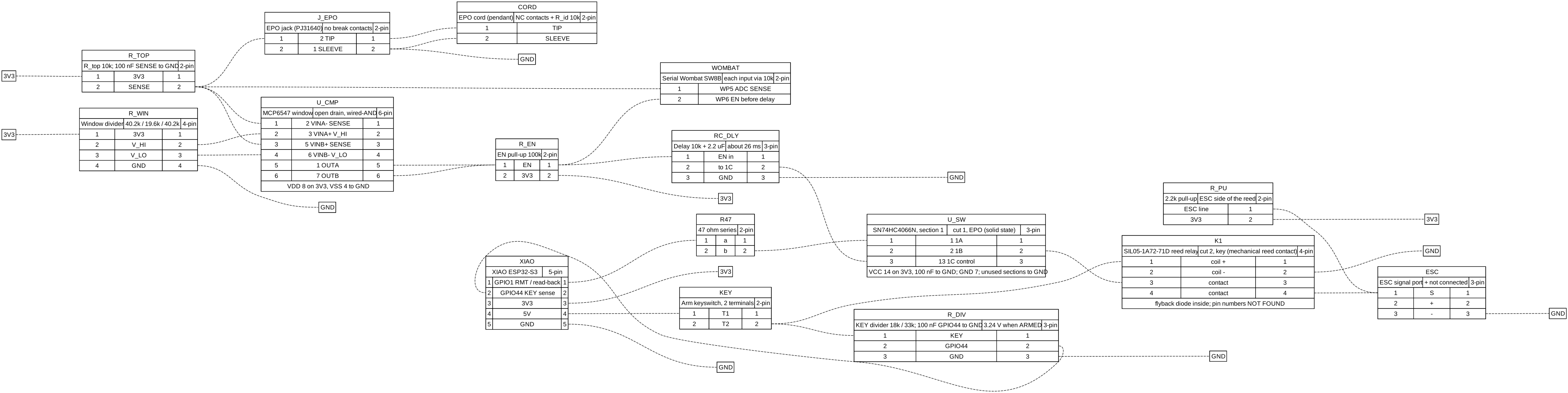
The two cuts in the ESC signal line. Cut 1 is the emergency stop: a window comparator watches the corded loop and opens one section of a 4066 analog switch. Cut 2 is the key: it powers a reed relay whose contact sits in the same line. Either cut alone stops the ESC’s frames, and because they are different technologies, no single part failure defeats both. The reed relay’s pin numbers and coil resistance are not found yet (its datasheet could not be fetched), so its block names functions only. WireViz 0.4.1, nets checked by th-eda, 2026-10-19 (thrust-stand). Open the full diagram.
The two switches are deliberately different kinds of part. The emergency stop’s is one section of a 4066 analog switch, which is solid state. The key’s is a reed relay, which is a mechanical contact. A second 4066 section would have been simpler to wire, but it would share the same silicon, the same 3.3 V rail and the same path for a static discharge coming in on the ESC lead. One bad event could then weld both switches shut at once. A reed contact fails in different ways and for different reasons, so a single fault cannot take out both cuts. A side benefit: the key now switches the relay coil’s current, about 10 mA (an estimate), which is enough to keep the key’s own contacts clean.
The emergency stop window
Section titled “The emergency stop window”The corded emergency stop is a normally closed button in series with a 10k resistor, inside the cord, on a 3.5 mm plug. The box puts its own 10k above that loop and watches the voltage in the middle with a window comparator. The window accepts a loop between 6.7k and 14.9k, and only then does the switch close.
A plain “closed means OK” input would accept a short circuit, so the window exists to reject every way the loop can be wrong. Pressing the button, cutting the cord or unplugging it reads open. A short reads zero. A load cell plugged into the emergency stop jack by mistake reads about 1k. All of them fall outside the window and open the switch. The window is set by ratios of the same 3.3 V rail, so it does not drift with the supply, and if the rail dies the switch opens anyway.
Why the hardware cut waits 26 ms
Section titled “Why the hardware cut waits 26 ms”The comparator’s output reaches the 4066 through a 10k resistor and a 2.2 µF capacitor, about 26 ms of delay. That sounds backwards for a stop button, but it lets a healthy firmware act first. The firmware reads the same signal ahead of the delay, sees the trip at once and sends a clean DShot stop, and then the hardware cut follows. If the firmware has crashed, the hardware cut still arrives, 26 ms later.
Proving the cuts work
Section titled “Proving the cuts work”A switch that has welded shut looks exactly like a healthy closed one, until the day it is needed. So the firmware tests both cuts without any extra wiring. Between DShot frames it turns its own output pin into an input with a weak pull-down. The 2.2k pull-up on the far side of both switches can only win if both are closed, so the pin reads HIGH with both closed and LOW if either is open.
That one reading answers three questions at the moments they matter:
- When the key goes to SAFE, the pin must read LOW. If it does not, the reed is welded and the box refuses to arm.
- When the key goes to ARMED with the emergency stop healthy, the pin must read HIGH before the first frame. If it does not, a contact or a joint has failed.
- When the emergency stop trips with the key still on, the pin must drop within about 50 ms. If it does not, the 4066 is stuck.
Any failed check latches a fault, so a welded contact shows up before the next run rather than during it.
What the cuts do not cover
Section titled “What the cuts do not cover”The cuts stop the signal, not the power. The box’s ESC output connector is live whenever the pack is plugged in, so the plug order matters: the ESC lead goes into the box first, and the pack goes in last, into the anti-spark XT90-S input.
Nothing in the box can stop a blade that has already let go. A failed blade leaves in the prop’s plane of rotation, so the bench layout keeps the box, the operator, the pendant and the pack out of a band 30° either side of that plane, measured from the hub. That band is our own conservative choice, not a published figure. As drawn, the box’s nearest corner sits about 35° out of the plane, 192 mm along the motor axis from it. The prop is also set so that its wash blows away from the pillar and the box.
Sources
Section titled “Sources”The figures on this page come from thrust-stand’s design notes for the box (docs/esp32-box.md), its firmware notes (docs/firmware.md), the stand’s hardware facts, and the firmware’s throttle owner, chain monitor and INA228 driver. That repository is not public yet. The current limits and the duty cap come from Propulsion, and the bench layout figures from thrust-stand’s model coordinates (2026-10-19).
Comments
Comment on the whole page here, or on one section or step with the button beside it.