
XY squareness
Test prints / Machine baseline
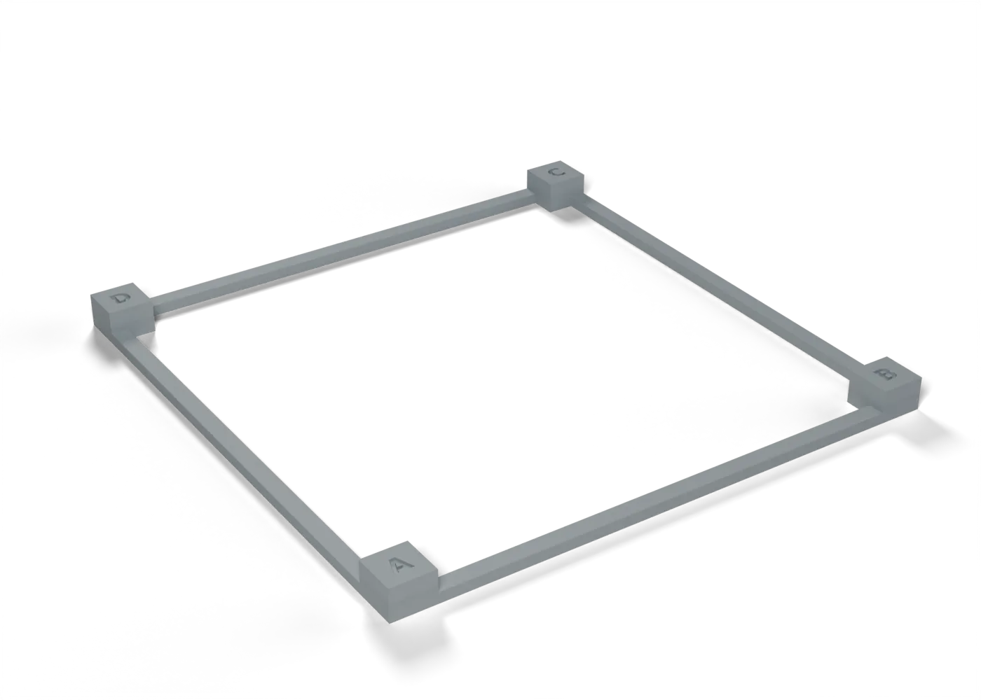
A 100 mm frame on four posts: the two diagonals give the skew, the sides give the XY scale.
Toolpaths
Every extrusion move in the G-code, layer by layer. Drag the layer slider, scrub through the top layer, or play the print.
Toolpaths load when you open this view.
Read from the G-code that the printer gets. The clock adds each move at its programmed speed, without acceleration or travel, so it is shorter than the slicer's estimate.
Procedure
What it is for. It shows whether the printer’s X and Y axes are square to each other, and its X and Y scale. The wing span is 1,484 mm across spar joints, so 0.1° of skew moves a tip about 1.3 mm.
Print. Print in plain PLA.
Measure. With calipers, measure the diagonal AC and the diagonal BD across the outer corners of the posts, then the sides AB and AD.
Pass. Square: AC = BD = 141.42 mm. The skew angle is asin((AC² − BD²) / (4 × AB × AD)), about (AC − BD) / 141.4
rad on this frame. AC and BD must be within 0.25 mm of each other (0.1°), and AB and AD 100.00 ± 0.10 mm.
Record. AC, BD and the skew angle. Record AB and AD as the XY scale.
In the tuning log
- XY squareness and scaleTo test
Comments
Comment on the whole page here, or on one section or step with the button beside it.