
Beacon
Boards / always-on power, GPS and LoRa
The beacon keeps the GPS and two LoRa radios on an always-on supply, so that a downed aircraft can send its position.
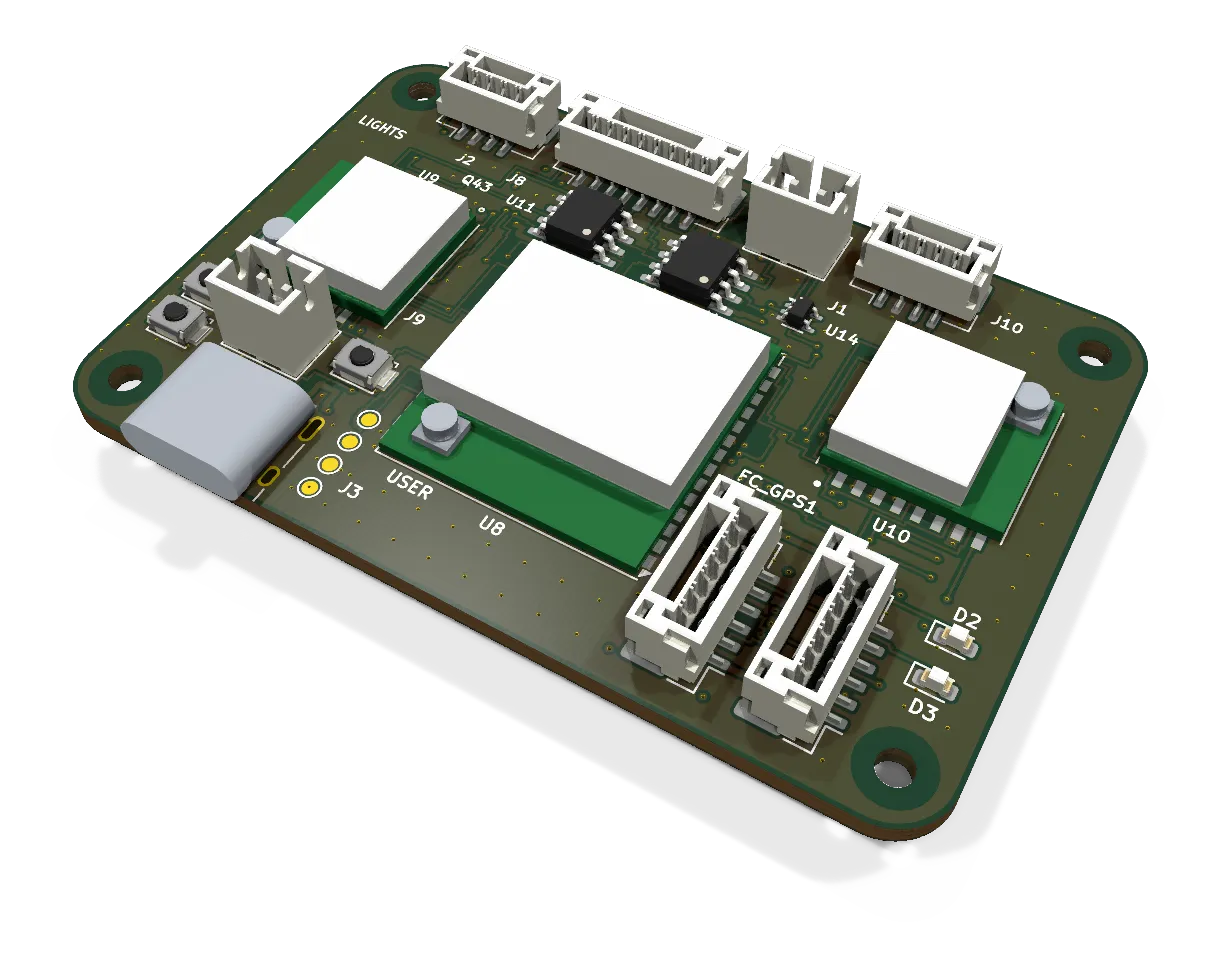
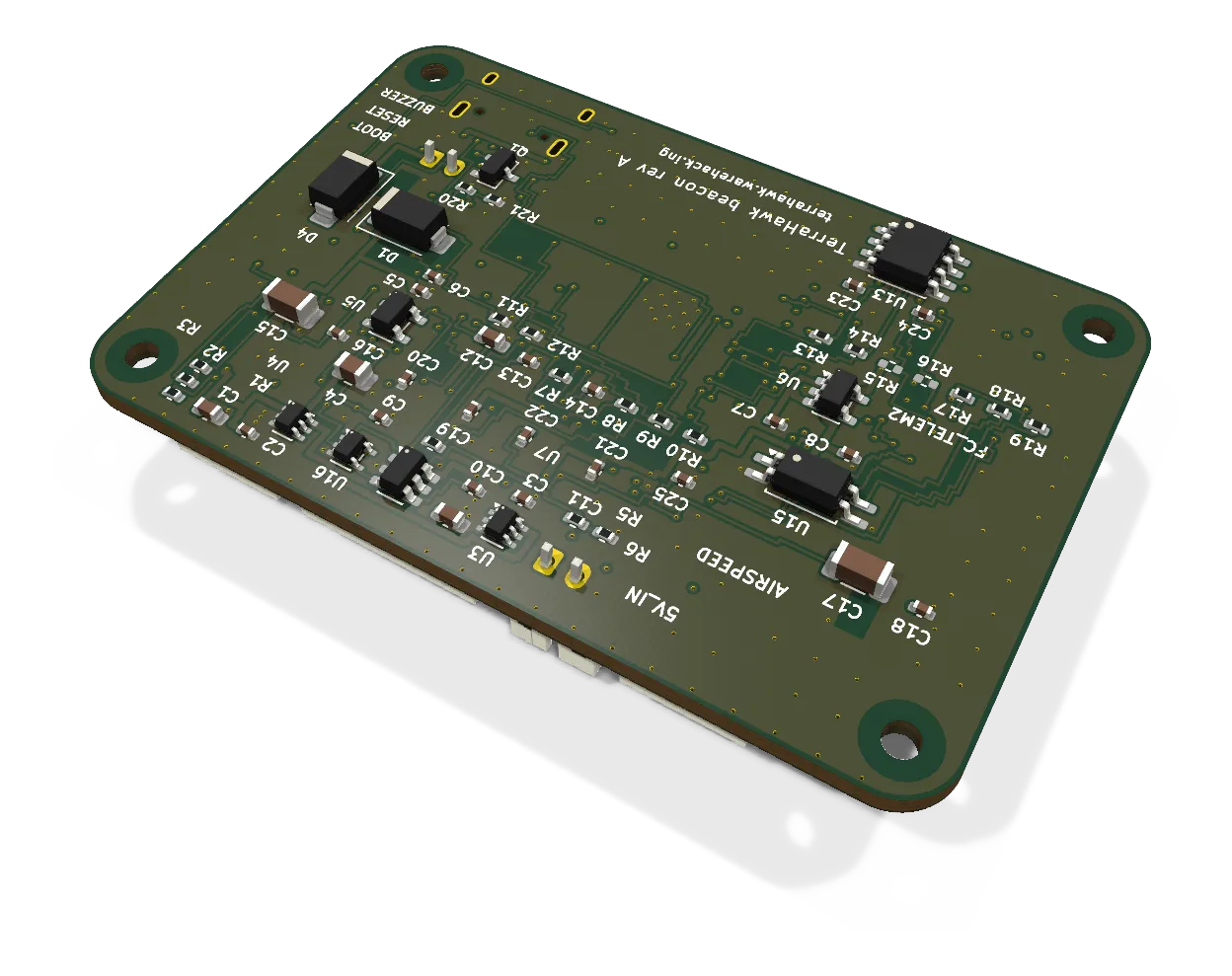
- Revision
- A draft
- Sheets
- 1
- Parts
- 80
- Board
- 60 × 40 mm
- Copper layers
- 4
- Footprints
- 84
- Location
- aircraft and dock
- Bus
- none: isolated UARTs and I2C to the FC
- Status
- Rev A draft: routed, DRC clean
What it does
The beacon is the LoRa telemetry radio and the always-on power domain. Two radios in diversity carry MAVLink, RTK corrections and SITE_CLR (mLRS firmware). The board also supplies the Q43 GPS and drives a buzzer.
Ideal diodes OR the main 5 V with +5V_LIGHT from the lights node. +5V_LIGHT is set higher, so the lighting battery carries the load by day. If the flight pack is lost, the lighting battery keeps the Q43 and the radios on. Each line to the FC goes through an isolator, so an FC that is off gets no back-feed.
Where it sits
On the aircraft, the beacon goes in the belly spar box at about Y 302. This is for Fuselage C. Until then, the XIAO with one Wio-SX1262 stays in the nose.
At the dock, the same board goes in the bay beside the Rover board. The dock board does not have the aircraft-only parts: the lights link J2, the Q43 and its load switch (J8), the GPS and compass isolators (J6), the buzzer (J9) and the airspeed tap (J10); the EDA README lists the refs. Thus it has no lighting battery backup. Its radios connect to two 915 MHz dipoles on the beacon post.
Main parts
| Part | Function |
|---|---|
| ESP32-S3-WROOM-1U-N8 | MCU, runs mLRS. The 1U has a U.FL for the S3’s own 2.4 GHz radio (since 2026-10-07) in place of the WROOM-1’s PCB antenna, so WiFi or BLE can reach a phone at the recovery site; which one, and when, is firmware’s call |
| 2 x Seeed Wio-SX1262 | SX1262 LoRa at 22 dBm with TCXO and the antenna switch inside the module; the module the XIAO carries, so mLRS already runs it. Replaced the Heltec HT-RA62 on 2026-10-07 because the Heltec is factory-direct only |
| 2 x LM66100 | Ideal-diode OR of the two 5 V supplies |
| 2 x AP2112K-3.3 | 3.3 V for the ESP32 and the radios; 3.3 V for the isolators’ FC side, from the FC port’s 5 V |
| TPS22917 | Q43 load switch |
| 2 x ISO7721, ISO1541 | UART and I2C isolators |
| EL357N | Main-power sense |
Connections
| Connector | Type | To |
|---|---|---|
| J1 | PH-2 | Main 5 V (dock: bay supply) |
| J2 | GH-4 | Lights node J6: +5V_LIGHT, GND, UART |
| J3 | USB-C | Bench power and firmware upload |
| J6 | GH-6 | FC GPS1 |
| J7 | GH-6 | FC TELEM2 (dock: Rover board TELEM) |
| J8 | GH-8 | Q43 |
| J9 | PH-2 | Buzzer |
| J10 | GH-4 | Airspeed sensor |
| IPEX on each radio | U.FL (IPEX first generation) | Taoglas CAB.011 pigtail, 95 mm, to an SMA bulkhead on the spar-box wall at that radio’s station: A port Y 306, B starboard Y 291.5 |
Status
Rev A draft, routed on 2026-10-07 (EDA 99ed160; the isolator sides were corrected and the radios swapped to the Wio-SX1262 the same day, each with a re-route). The board is 60 x 40 mm, 4 layers, 80 parts, 65 nets. All 251 connections are routed, with a 2.5 mm ground-stitching grid. DRC gives 0 errors at every severity, and the board matches the schematic. Every part number is confirmed at DigiKey, the Wio-SX1262 included; only the USB-C receptacle comes from elsewhere (LCSC). The board keeps the ESP32-S3 because mLRS has no ESP32-P4 port. Before the harness, do a check of the Q43 pin 1 end and of the Wio-SX1262 land (the pad split on the module edge) on the real modules.
Schematic and layout
The 3D board loads when you open this view.
Theory of operation
This page reads the beacon schematic in signal order: power in, the ideal-diode OR and the two 3.3 V rails, the ESP32, the two LoRa modules, the isolated links to the flight controller, and the ports and buzzer. Every part is named by its reference designator, and each value carries its reason and source where the design notes give one. Where the notes say ESTIMATE or VERIFY, that word stays.
Power in
Two 5 V supplies arrive and either can carry the board. J1 (PH-2) brings main 5 V from the beacon’s own BEC on the flight pack, with C3 (4.7 uF) across it. J2 (GH-4) brings +5V_LIGHT from the lights node’s 2S lighting battery, with C1 (10 uF) and C2 (100 nF). The lights node sets +5V_LIGHT at 5.2 V, gives about 1.5 A, and stays alive down to that battery’s cell cut (lights.md). J2 also carries a UART between the two boards: “lost mode” to the lights and the battery state back. R1 and R2 (1 k) sit in series with the two lines, the value the lights node uses on its end, and R3 (100 k) pulls the ESP32’s receive line up to +3V3.
U3 and U4 are the LM66100 ideal diodes, 95 mohm and 1.5 A per the design note. U3 passes main 5 V and U4 passes +5V_LIGHT; their outputs join at +5V_AO, the always-on rail, with C4 (22 uF, 10 V). Each enable pin is tied to ground, so both stay on. Because +5V_LIGHT sits 0.2 V above main, U4 conducts by day and the lighting battery carries the Q43, the radios and the buzzer. If the lighting rail droops, U3 takes over with no dropout, and when main goes, nothing changes over at all (th-avionics’ point 1: the Q43 keeps its fix and the radios do not reset at a pack swap).
D1 (SS14) brings USB VBUS from J3 into +5V_AO on the output side of the OR. The ideal diodes block reverse current, so a laptop on the USB-C can never drive J1, which at the dock is the bay’s shared 5 V (th-hangar). With J1 live at 5.0 V, the OR output wins over the 4.7 V behind D1 and the USB supplies nothing.
In a model of this rail (LTspice, sim/beacon/or-handover.cir in the EDA repo; the LM66100, the SS14 and the source impedances are stand-ins marked ESTIMATE) +5V_AO sits at 5.18 V while the lighting battery carries, moves to 4.95 V when that rail dies and main takes over, and to 4.55 V when main dies too and USB carries 350 mA through D1. Each move is a step to the next source’s level with no undershoot below it; C4 carries the load for 12 us and 34 us while the next ideal diode closes, and the reverse current into each dead source settles at nanoamps. The one number to check on the real part is the charge that flows back during the LM66100’s own response time, 80 to 90 nC in the model.
Rails
U5 (AP2112K-3.3) regulates +5V_AO down to +3V3 for the ESP32, the radios and the always-on side of every isolator, with C5 (1 uF) on its input and C6 (4.7 uF) on its output. One Wio-SX1262 transmitting at 22 dBm draws 125 mA (datasheet), and only one transmits at a time; each draws 7.6 mA in receive; the ESP32 draws about 60 mA with WiFi off (ESTIMATE). The AP2112K’s 600 mA rating covers that (datasheet).
U6 is a second AP2112K-3.3 and it is the key to the isolation. Its input is +5V_FC, the 5 V pin of the GPS1 port on J6, and its output +3V3_FC powers only the flight-controller side of the three isolators, with C7 (1 uF) and C8 (4.7 uF). The LUX brings 5 V, not 3.3 V, to its ports (th-avionics’ point 3), so the board makes its own FC-side 3.3 V. With the flight controller off, +3V3_FC is at 0 V and that side of every isolator is dead.
U7 (TPS22917) is the load switch between +5V_AO and Q43_5V, the Q43’s supply, with C11 (10 uF) on its output and C10 (1 nF) on CT. R4 (100 k) pulls Q43_EN up to +3V3, so the switch is on by default, and the ESP32 (IO39) drives it low to duty-cycle the Q43 in lost mode. U16 (74LVC1G32, C9 100 nF) ORs Q43_EN with MAIN_PRESENT before the ON pin. MAIN_PRESENT is a 10k/10k divider (R5, R6) off main 5 V: 2.5 V, a logic high for an LVC gate on 3.3 V (th-avionics’ point 4). While the pack is in, no firmware fault can drop the GPS and the compass.
MCU
U8 is the ESP32-S3-WROOM-1U-N8 (the U.FL variant since 2026-10-07, so the S3’s 2.4 GHz radio has an external antenna; same pins as the WROOM-1), decoupled by C12 (10 uF) and C13 (100 nF), and it runs mLRS. The variant rule is th-telemetry’s: N8 or N8R2 only, never an R8, because octal PSRAM takes GPIO35 to 37 and this board uses 35 and 36; never a 1.8 V-flash V variant, because GPIO47 and 48 carry the lights UART in the VDD_SPI domain and must run at 3.3 V. R7 (10 k) pulls EN up with C14 (100 nF) to ground, and SW1 (RESET) pulls it low. SW2 (BOOT) pulls IO0 low for the ROM loader. SW3 (USER) pulls IO42 low against R8 (10 k). Strapping pins 0, 3, 45 and 46 carry nothing else.
D2 (red) through R9 (1 k) is the mLRS “not linked” LED and D3 (green) through R10 (1 k) the “linked” LED; the pair reports the link, not one radio each (th-mlrs-xiao). J3 (USB-C) connects D+ and D- to the USB-JTAG on IO20 and IO19 for flashing and the CLI, with R11 and R12 (5.1 k) as the CC pull-downs. TP1 to TP4 bring out TXD0, RXD0, GND and 3V3.
Radios
U9 (radio A) and U10 (radio B) are Seeed Wio-SX1262 modules, each an SX1262 with a TCXO on DIO3 inside the module (1.7 to 3.3 V per the datasheet; the hal runs it at 1.8 V as the XIAO target does) and the antenna switch inside too. They run in diversity with one antenna each on the module’s own IPEX. Both share SPI on IO12, IO11 and IO13, the IO_MUX FSPI pins, and each has its own NSS, DIO1, BUSY, NRST and RF_SW. The switch is a PE4259 wired as Semtech’s reference: the SX1262’s DIO2 drives one control and goes high by itself on transmit (SX_USE_DIO2_AS_RF_SWITCH), and RF_SW is the other, which the firmware drives high for receive and low for transmit; both high is undefined for the switch, so RF_SW keeps its own GPIO and is never tied high (th-mlrs-xiao). The ANT castellation stays open with no copper under it: the RF leaves through the IPEX and the board carries no RF line.
C15 and C17 (100 uF, 6.3 V) sit under U9 and U10, with C16 and C18 (100 nF) beside them. The 100 uF covers the transmit burst: it was sized when the land was the Ra-01SH’s, whose maker asks for a 3.3 V supply able to give over 1 A peak with under 100 mV ripple (Ra-01SH-P specification, section 6.4), and it stays for the Wio, whose 125 mA at 22 dBm is a smaller step than the one modelled below.
In the model (sim/beacon/radio-burst.cir; the AP2112K is a 3.3 V source with 100 mohm and a stepped response time, ESTIMATE) radio A steps from 8 mA to 140 mA in 2 us (the Heltec figure the deck was written against; the Wio’s 125 mA step is smaller, so the result holds with margin). With C15 fitted the module pin droops 15 mV against a fast regulator and 30 mV against a slow one, and the 100 uF supplies 80 mA of the step itself. Without it the droop is 35 mV and 103 mV, the slow case sitting at Ai-Thinker’s 100 mV limit with a 3.12 V minimum at the regulator’s 2 % low end. The capacitor holds the whole 3.3 V rail: radio B and U5’s output see the same droop to within 1 mV.
Isolated links to the flight controller
Every line to the flight controller crosses an isolator. Pins 1 to 4 of each isolator are the flight-controller side, powered by +3V3_FC from U6; pins 5 to 8 are the always-on side, powered by +3V3 from U5; each supply pin has 100 nF. The lines the flight controller drives enter on its own side, so a dead flight controller meets only an unpowered input, never a driven output. With the flight controller off, nothing crosses: bench check 1 of the spec holds by construction. The spec asks for at least 1 Mbd on the UARTs (the GPS link runs at 230,400 baud, the radio link at 115,200), which rules out a slow transistor optocoupler there.
U11 (ISO7721, C19 and C20) carries the GPS UART: GPS1 TX crosses to the Q43’s RX and the Q43’s TX crosses back to GPS1 RX. U12 (ISO7721, C21 and C22) carries the radio UART the same way between TELEM2 and the ESP32’s IO21 and IO8. The ISO7721 is the default-high part, not the ISO7721F: with its input side unpowered its output rests high, so a dead flight controller leaves no break on a receive line. U13 (ISO1541, C23 and C24) carries the compass I2C from the Q43’s QMC5883P to the flight controller, because an optocoupler cannot pass open-drain I2C without latch-up. R13 and R14 (4.7 k) pull SDA_AO and SCL_AO up to +3V3. R15 and R16 (4.7 k) on the flight-controller side are DNP: with everything unpowered, measure SCL and SDA to the LUX’s 3.3 V and fit them only if nothing else pulls up (th-avionics’ point 3).
U14 (74LVC1G08, C25) ANDs the flight controller’s isolated TX with the ESP32’s TX on IO35, both idle high, into the Q43’s RX, so the ESP32 configures the Q43 only when the flight controller is silent. R17 (10 k) pulls IO35 up, so the Q43 sees no break while the ESP32 is in reset or booting (th-telemetry). The ESP32 reads the Q43’s TX directly on IO9: one driver, two receivers. U15 (EL357N) senses main power: R18 (1 k) feeds its LED from main 5 V and its transistor pulls MAIN_SENSE on IO36 low against R19 (100 k) while main is present. Speed does not matter here, so a plain LED optocoupler serves.
Ports and the buzzer
J6 (GH-6) is the GPS1 port in Pixhawk order (LUX F765 README). Its 5 V pin feeds U6 and J10 only; it never reaches the Q43, which takes power from Q43_5V alone, as the spec requires. J7 (GH-6) is TELEM2 with CTS and RTS unused. J8 (GH-8) is the Q43 in the order GND, TX2, RX2, SDA, SCL, TX1, RX1, VCC from Waveshare’s drawing; TX2 and RX2 are open, and which end is pin 1 is to VERIFY with a meter on the module. J10 (GH-4) is the airspeed tap: the MS4525DO shares the GPS port’s I2C and stays on the flight-controller side of U13; its pin order follows the sensor board’s silkscreen, to VERIFY.
J9 (PH-2) takes a 5 V piezo or magnetic sounder, 85 to 100 dB per the spec, between +5V_AO and the drain of Q1 (AO3400A). R20 (100 R) couples IO38 to the gate and R21 (100 k) holds the gate low, so the sounder stays silent while the ESP32 boots. D4 (SS14) across the sounder clamps the flyback when Q1 turns off.
In the model (sim/beacon/buzzer-flyback.cir; the sounder is 42 ohm with 15 mH, ESTIMATE for a 12 mm magnetic transducer, driven at 2.4 kHz) the drain of Q1 peaks at 5.3 V with D4 fitted and the transistor dissipates under 0.1 mW. Without D4 the drain reaches the AO3400A’s 30 V breakdown every cycle and the transistor absorbs 57 mW with 1.6 W peaks. The diode also keeps the coil current circulating through the off half-cycle, so the sounder is driven with 36 mA peak to peak instead of 53, the usual trade for a clamped drive.
Failure modes the circuit covers
- Flight controller off: +3V3_FC is at 0 V, so U11, U12 and U13 pass nothing and their always-on outputs rest high. No current reaches the flight controller’s pins.
- Main 5 V lost: U4 keeps carrying the rail from the lighting battery, as it already does by day. U15 releases MAIN_SENSE and the ESP32 starts the beacon and, after the set time with no movement, the buzzer.
- Lighting battery cut: U3 carries the rail from main 5 V with no dropout.
- Both lost on the bench: D1 feeds +5V_AO from USB, and the ideal diodes keep the laptop from driving J1.
- ESP32 in reset or booting: R17 holds the Q43’s RX idle high through U14, R4 holds the load switch on, R21 holds the buzzer off.
- Firmware rule: while MAIN_SENSE reports main present, the ESP32 keeps IO35 idle high, because the flight controller injects RTCM at 230,400 baud continuously and anything from the ESP32 would corrupt it. U16 enforces the same rule for the load switch in hardware.
Files
From the EDA repository at revision b201257 (2026-10-12). Open the files in KiCad 10 or later.
Comments
Comment on the whole page here, or on one section or step with the button beside it.