
Lift ESC, round under-motor
Boards / Round single-channel DroneCAN ESC under each lift motor (STM32L431, AM32, 6S), with castellated wire tabs.
The lift ESC drives one lift motor and gets its commands over DroneCAN.
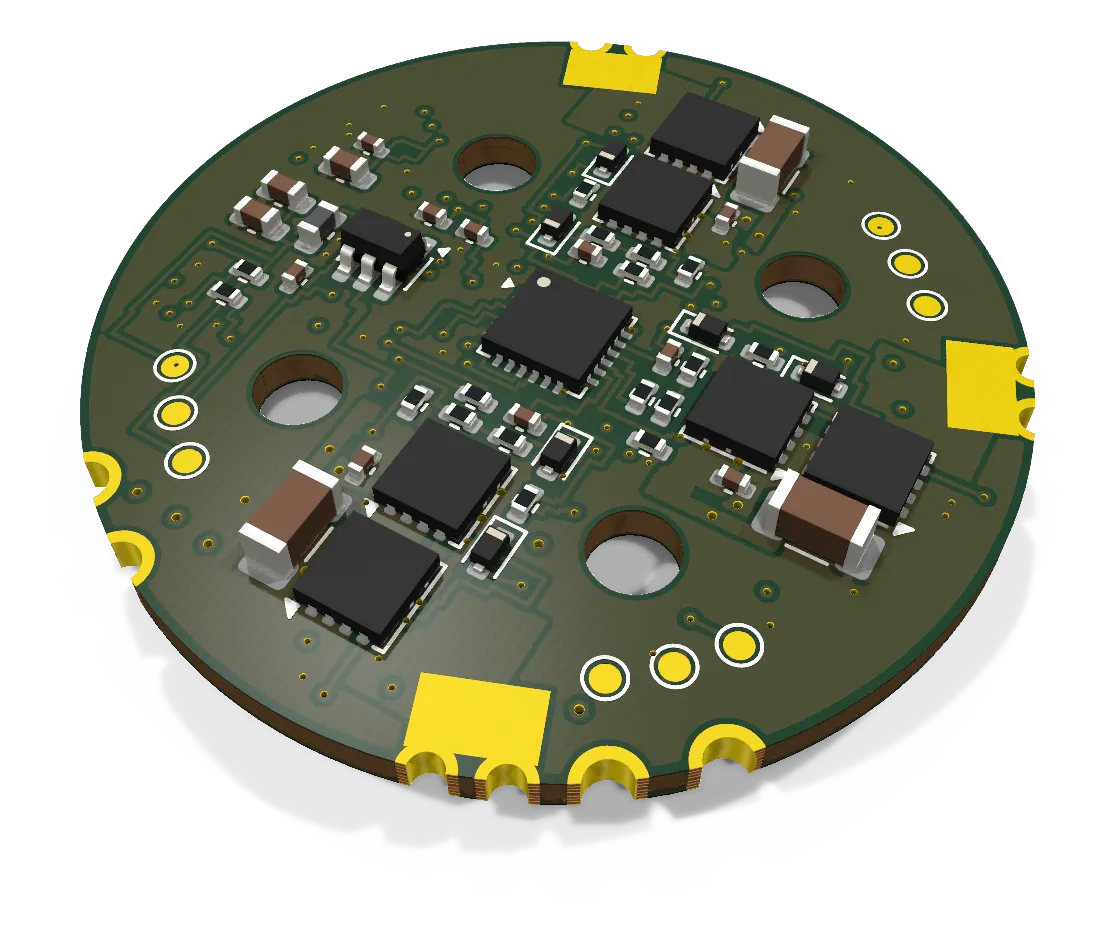
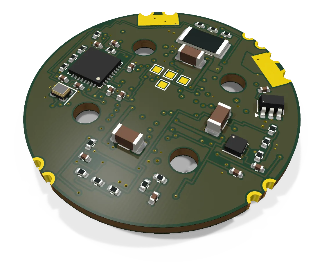
- Revision
- A draft
- Sheets
- 1
- Parts
- 103
- Board
- 34 × 34 mm
- Copper layers
- 8
- Footprints
- 107
- Location
- aircraft
- Bus
- DroneCAN bus 1 (lift ESCs only) on our FC, through the CAN tap
- Status
- Rev A draft: autorouted, 24 of 144 connections open
This board is licensed under the CERN-OHL-S-2.0 (CERN Open Hardware Licence Version 2, Strongly Reciprocal). Part of its design follows OpenESC-20x20, which has the same licence. The KiCad files on this page are its source.
What it does
The lift ESC is a single-channel 6S ESC on a round 34 mm board. It runs AM32 firmware with DroneCAN on an STM32L431. It finds the rotor position from the back-EMF of the three phases, with no motor sensors. It measures the motor current with a low-side shunt and the pack voltage with a divider.
The power stage follows OpenESC-20x20 (CERN-OHL-S-2.0). th-avionics wrote the AM32 target TERRAHAWK_L431_CAN for it. The bus parts are on a separate board, the CAN tap. The ESC connects to it through a four-wire logic link.
Where it sits
There is one lift ESC under each lift motor, four in the aircraft. Each board sits on the motor mount pad of its pod, under the motor, on 6 mm standoffs. Its four 3.2 mm holes are on the 19 mm bolt circle that every 28xx-class motor uses (the mounts’ 13.44 mm square), so the EMAX ECO II 2807 fits the same pattern as the XING2 2809 it replaced. The ECO II’s 33.9 mm bell sits inside the disc, its lead exit does not reach below the mounting face (Ryan measured it on 2026-10-07), and the leads, which leave between two adjacent bolt holes, are routed by clocking the motor: the leads point along the board’s 180 degree axis, away from the VTOL spar toward its free end, where no rim tab sits within 58 degrees. The top face points to the motor. The bottom face sits in a 1.5 mm pocket in the PETG pad. The pod feed comes along the spar bore, with two 100 uF 35 V capacitors in the bore.
This board is the end state for the lift motors (Ryan, 2026-09-29). The TBS Lucid 4-in-1 flies first. The DroneCAN pod path follows, one pod at a time. The ESC nodes are 24 to 27, by motor number.
Main parts
| Part | Function |
|---|---|
| STM32L431KCU6 | MCU. Runs AM32 with DroneCAN. The pins are fixed by AM32 HARDWARE_GROUP_L4_B |
| NSG2065Q | Three-phase gate driver with internal bootstrap diodes |
| Six BSZ018N04LS6 | 40 V, 1.8 mOhm FETs, three half bridges |
| LMR54406 | Buck converter, pack to 10 V for the gate driver |
| TLV76733 | LDO, 3.3 V for the MCU and the current amplifier |
| 0.5 mOhm shunt and INA180A3 | Motor current: 50 mV/A, 66 A full scale |
| 24 MHz oscillator | MCU clock |
| NTC thermistor | Fitted for later use. AM32 does not read it on the L431 |
Connections
| Connector | Type | To |
|---|---|---|
| BAT+, BAT- | Castellated edge tabs, bottom face | Pod feed, 16 AWG pair |
| Phase A, B, C | Castellated edge tabs, top face | Lift motor leads, 18 AWG |
| CAN link | Four 1.0 mm pads (3V3, GND, TXD, RXD) | CAN tap, four 28 AWG wires, less than 100 mm |
| Bench pads | Nine 1 mm pads | SWD, reset, telemetry, signal, current and 10 V, for the bench only |
Status
Rev A draft, 103 parts. The board has eight layers with 2 oz outer copper (Ryan’s choice). The autoroute run of 2026-10-06 leaves 24 of 144 connections open. All of them are at the two QFN packages. DRC shows 0 errors other than three accepted starved thermals, and schematic parity is 0. A gate-drive simulation set the gate resistors and confirmed DEAD_TIME 45. The next steps are hand routes in KiCad, silkscreen, a full DRC and a pre-order review.
Schematic and layout
The 3D board loads when you open this view.
Files
From the EDA repository at revision b201257 (2026-10-12). Open the files in KiCad 10 or later.
Comments
Comment on the whole page here, or on one section or step with the button beside it.