
Flight controller
Boards / STM32H743 flight controller with two CAN buses, Pixhawk 6C Mini compatible; MCU pins from the hwdef.
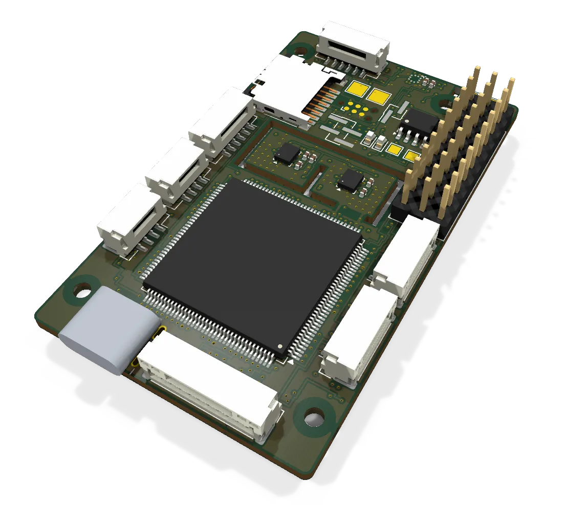
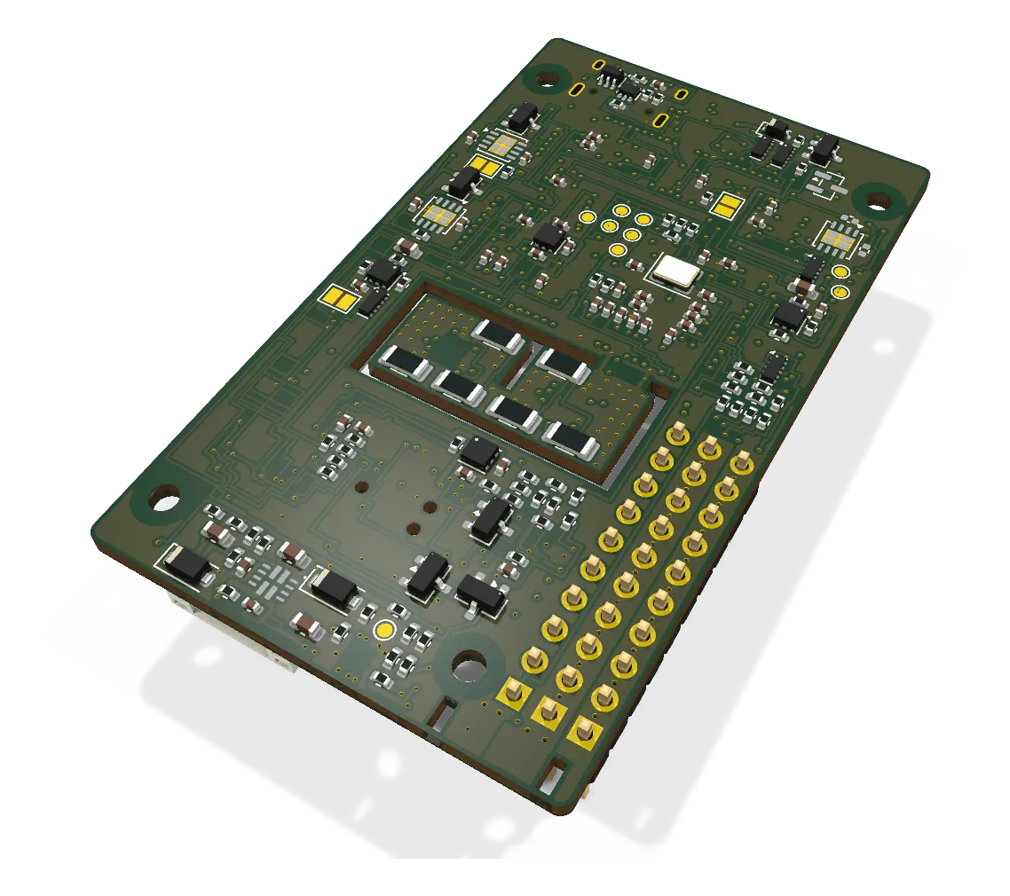
This board is our own FC: it runs ArduPlane and controls the motors, the elevons and both CAN buses.
- Revision
- A draft
- Sheets
- 1
- Parts
- 192
- Board
- 38 × 64 mm
- Copper layers
- 6
- Footprints
- 196
- Location
- aircraft
- Bus
- DroneCAN bus 1 (lift ESCs only) and bus 2 (all other nodes); the FC is on both
- Status
- Rev A draft: autorouted, 89 connections open, DRC 0 errors
What it does
This board is our own flight controller (FC). It runs ArduPlane on an STM32H743. It keeps the MCU pin map of the Holybro Pixhawk 6C, so the hwdef is a short diff of a board that ArduPilot flies. The connectors use the Pixhawk 6C Mini pinouts.
The FC has two CAN buses with one DroneCAN driver each. Bus 1 carries the four lift ESCs and nothing else. Bus 2 carries all other DroneCAN nodes. A fault on bus 2 cannot stop the lift motor commands.
Where it sits
The 38 x 64 mm board sits in the FC bay on 2 mm M2 spacers over the Avionics Plate, from Y 276 to Y 340 (th-blender, 2026-09-28). USB-C and GPS1 are on the aft edge, in the hatch opening.
The aircraft flies the Lumenier LUX F765 NDAA first. This board follows it. A power module on the pack lead supplies 5 V and the pack voltage and current signals.
Main parts
| Part | Function |
|---|---|
| STM32H743ZIT6 | MCU, LQFP-144. An STM32H723 fits the same footprint |
| ICM-42688-P (SPI1) and LSM6DSV16X (SPI6) | Two IMUs on two SPI buses, on a heated island |
| BMP388 | Barometer on I2C4 |
| FM25V02A | FRAM for parameters on SPI2 |
| Hirose DM3D-SF | microSD socket for logs, on SDMMC2 |
| TPS2121 | Power mux for POWER1 and POWER2, with an overvoltage cut-off at 5.75 V typical |
| Two TLV75733P | 3.3 V main rail and switched 3.3 V sensor rail |
| Two TPS2553 | Switched 5 V: HIPOWER (TELEM2 only) and PERIPH (GPS, TELEM1, bus 2 power) |
| Three TJA1051TK/3 | CAN transceivers. The third is not fitted (CAN3 option) |
Connections
| Connector | Type | To |
|---|---|---|
| POWER1 | JST GH-6 | Power module: 5.2 V, current signal, voltage signal |
| POWER2 | Solder pads | A second 5 V source (reserved) |
| USB-C | USB 2.0 | GCS and firmware load |
| GPS1 | JST GH-10 | Waveshare Q43 NEO-F9P: GPS, compass on I2C1, safety switch, buzzer |
| GPS2 | JST GH-6 | Second GPS (UART8, I2C2) |
| TELEM1 | JST GH-6 | Telemetry radio (UART7, flow control) |
| TELEM2 | JST GH-6 | Serial device on HIPOWER 5 V (UART5) |
| CAN1 | JST GH-4 | Bus 1 harness stub to the lift ESCs. No VCC |
| CAN2 | JST GH-4 | Bus 2 harness stub. Pin 1 VCC from PERIPH |
| Servo header | 3 x 10 pins, 2.54 mm | Outputs 1 to 10: pusher on 1, 2 spare; 3 to 6 carry the lift motors by DShot with the 4-in-1 ESC and are spare with the DroneCAN pods; elevons on 7 and 8; camera on 9 and 10 |
| BEC pads | Two solder pads | Servo-rail BEC through a 20 AWG pigtail and an MR30 plug |
| FMU debug | Tag-Connect TC2030-NL | SWD |
Status
Rev A draft, ERC 0 errors. The six-layer layout is the autoroute of 2026-09-29 with scripted hand routes on top. On 2026-10-07, 89 connections are open, DRC shows 0 errors and schematic parity is 0. The next step is to route the open connections by hand in KiCad. The hwdef compiles. No board is built.
Schematic and layout
The 3D board loads when you open this view.
Files
From the EDA repository at revision b201257 (2026-10-12). Open the files in KiCad 10 or later.
Comments
Comment on the whole page here, or on one section or step with the button beside it.