
CAN joiner
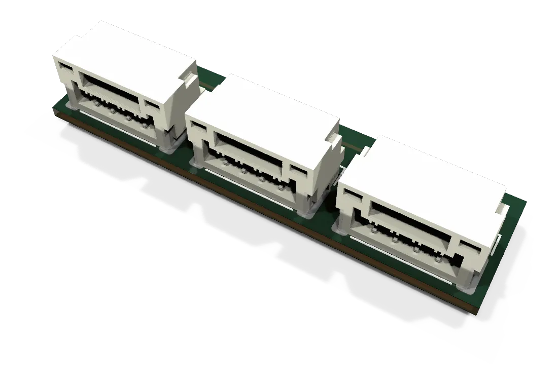
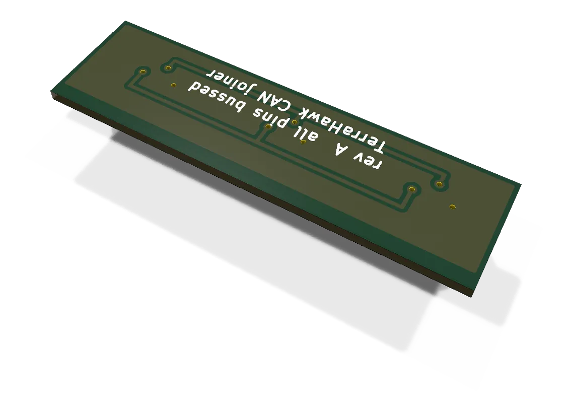
Boards / Three JST GH-4 headers with every pin bussed and no terminator; 29 x 8 mm on 0.8 mm FR-4, seven per airframe, panelised six-up.
The CAN joiner connects three CAN harness plugs at one point on a bus.
- Revision
- A.1
- Sheets
- 1
- Parts
- 3
- Board
- 29 × 8 mm
- Copper layers
- 2
- Footprints
- 3
- Location
- aircraft
- Bus
- DroneCAN bus 1 and bus 2, as a harness part, not a node
- Status
- Rev A.1: routed, DRC clean, fabrication files frozen
What it does
The CAN joiner is a passive board with three JST GH-4 side-entry headers. All four pins of each header are bussed: pin 1 VCC, pin 2 CAN_H, pin 3 CAN_L, pin 4 GND. A node lead, a harness leg or a terminator plug can join the bus at a joiner, with no splice.
The joiner has no terminator footprint. Terminator plugs in the harness end each bus, so a joiner never changes the termination. Pin 1 is bussed as the other pins are. On bus 1, the harness housings leave pin 1 empty.
Where it sits
The harness stays in the airframe, and the joiners stay with it. The pod path uses seven joiners in the aircraft:
| Location | Bus |
|---|---|
| Each of the four pods | Bus 1 |
| CAN1 at the FC, on a 60 mm stub | Bus 1 |
| CAN2 at the FC, on a 60 mm stub | Bus 2 |
| Beside the airspeed module | Bus 2 |
At a pod, the joiner sits in the tail of the ESC Pod Cradle S50. One 2.5 mm zip tie holds it in its seat. The plugs go in from below. With the 4-in-1 lift ESC, bus 1 has no nodes. The parts list gives the joiner count for the first build.
Main parts
| Part | Function |
|---|---|
| Three JST SM04B-GHS-TB | Side-entry GH-4 headers on the bottom long edge |
| Board, 29 x 8 mm | Two layers, 0.8 mm FR-4. GND is a pour on the back face |
Connections
| Connector | Type | To |
|---|---|---|
| J1 | JST GH-4, side entry | Harness leg (at a rear pod, the leg from the FC) |
| J2 | JST GH-4, side entry | Harness leg, or a node lead (at a rear pod, the leg to the front pod) |
| J3 | JST GH-4, side entry | Node lead or terminator plug (at a front pod, the terminator plug) |
The three headers are the same electrically. The pod assignments above are from the print plan for the S50 cradle.
Status
Rev A.1, 2026-09-30. Rev A.1 moved the bus tracks only, so that the top edge can hold the panel tabs. The outline, the headers and the pinout are the same as rev A. ERC, DRC at every severity and schematic parity show 0, with 0 open connections.
The joiner is smaller than the JLCPCB single-board minimum, so it is made as a panel of six (74.1 x 72.1 mm, KiKit). The fabrication files are frozen in fab/releases/can-joiner-revA1-2026-09-30/. Before a board order, do a check of the header rotation in the JLCPCB placement preview.
Schematic and layout
The 3D board loads when you open this view.
Files
From the EDA repository at revision b201257 (2026-10-12). Open the files in KiCad 10 or later.
Comments
Comment on the whole page here, or on one section or step with the button beside it.