
Position-light tab
Boards / bare Cree XP-E2 on a vertical aluminium tab
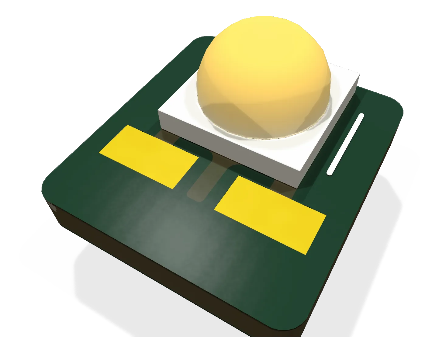
The position-light tab: one Cree XP-E2 (red, green or white) near the top of a 6 x 6.5 mm aluminium tab that stands behind a flush window in a wing tip or the tail cone, aiming the light at the horizon.
- Revision
- A draft
- Sheets
- 1
- Parts
- 3
- Board
- 6 × 6.5 mm
- Copper layers
- 2
- Footprints
- 3
- Location
- aircraft
- Bus
- none: a two-wire lead to the lights node's position-light channel
- Status
- Rev A draft: DRC clean (2026-10-10), not ordered
What it does
It holds one bare position-light LED with its axis horizontal. The wing tips are only 4.4 to 7.6 mm thick near the edge, too thin for a flat 10 mm star to face anywhere but down, so the light stands on a small tab instead: red at the port tip, green at starboard, both aimed forward-and-outboard, and white under the tail cone aimed aft, each behind a flush window. One board serves all three; the LED’s colour is chosen when it is fitted.
Where it sits
In a 1.1 mm slot behind the window, with the bottom 1.5 mm of the tab as a bare foot in the slot and, where the slot allows, a 10 x 10 mm aluminium pad under the foot for heat (th-blender). The position lights run at about a third of full current at night and are off by day (lights.md), about 0.25 to 0.4 W, which the tab sheds in a plastic slot; at full current (up to 1.1 W) it would run hot, so the night-only rule stays.
Main parts
| Part | Function |
|---|---|
| Cree XLamp XP-E2, red XPEBRD-L1-0000-00901, green XPEBGR-L1-0000-00F01, white XPEBWT-L1-0000-00EE4 | The LED, on the same recommended land as the XP-L (Cree gives both the same footprint), centred 4.5 mm up the tab |
| The board | 6.0 x 6.5 x 1.0 mm single-layer aluminium, the LED’s thermal pad poured down the centre of the face |
Connections
| Pad | What |
|---|---|
| + | LED anode, 2.0 x 1.0 mm wire pad 1.5 to 2.5 mm up the tab, left, for the 28 AWG lead |
| - | LED cathode, the same, right |
Status
Rev A draft, 2026-10-10 (EDA 6c46420): generated from gen/design.py and gen/layout.py, ERC 0, DRC 0 errors and 0 warnings at every severity with parity; STEP and render in the repo. The tab is 6.5 mm tall rather than the 6.0 first asked for, because the LED’s 3.3 mm pads leave no room for a wire pad above the foot on 6.0. Four pieces per order (three fitted, one spare) as bare boards with the strobe tabs.
Schematic and layout
The 3D board loads when you open this view.
Files
From the EDA repository at revision b201257 (2026-10-12). Open the files in KiCad 10 or later.
Comments
Comment on the whole page here, or on one section or step with the button beside it.