
Strobe facet
Boards / Cree XP-L on aluminium under a Carclo 10415
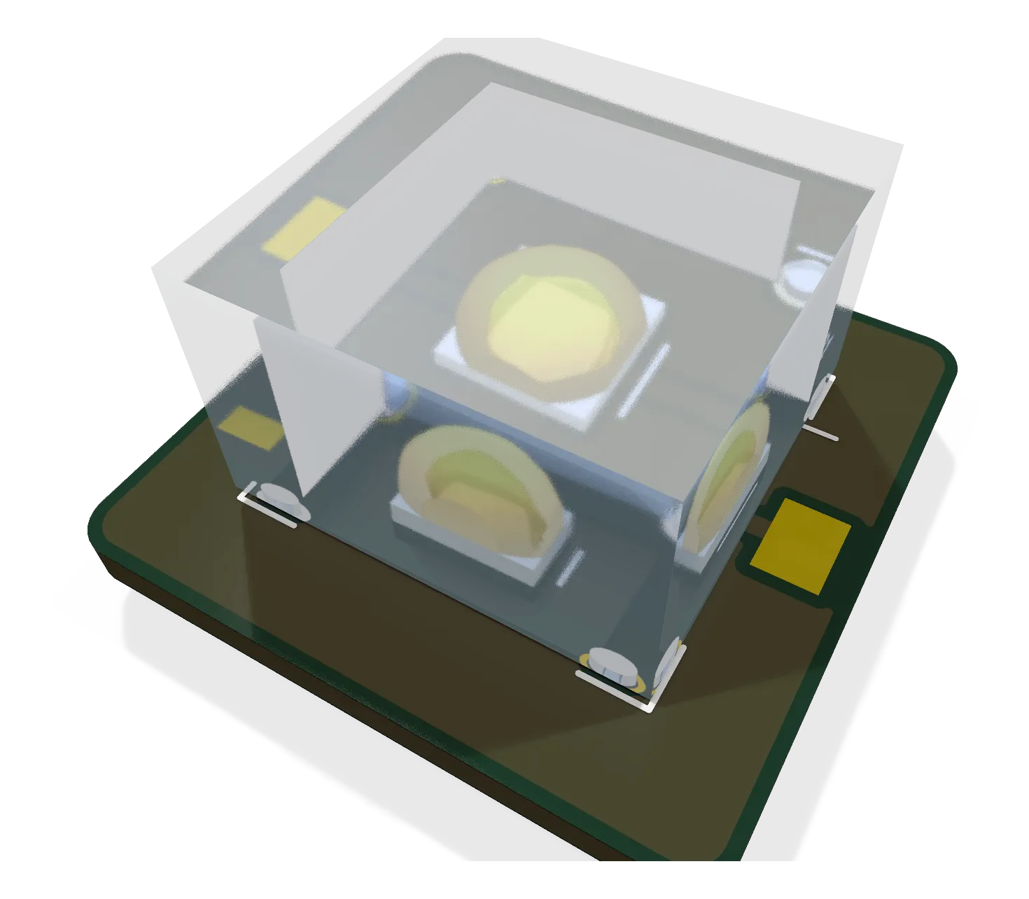
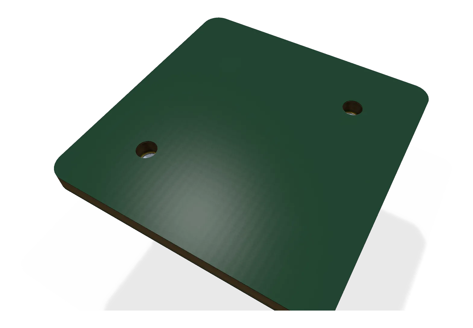
The strobe pod's facet board: one Cree XP-L on a 15 mm aluminium square under a Carclo 10415 lens; six of them, wired in series around a printed hexagonal core, make one anti-collision strobe.
- Revision
- A draft
- Sheets
- 1
- Parts
- 3
- Board
- 15 × 15 mm
- Copper layers
- 2
- Footprints
- 4
- Location
- aircraft
- Bus
- none: a two-wire LED string to the lights node's strobe channel
- Status
- Withdrawn 2026-10-10 with the hexagonal pod; a low-dome strobe layout replaces it
What it does
Withdrawn. Ryan rejected the hexagonal strobe pods on 2026-10-10 in favour of a low clear dome about 40 mm across and 10 mm proud, so this facet board and its pod are not built; the dome’s LED boards are being drawn in its place. The page stays as the record of the facet design.
It held one white LED and the lens that shapes its beam. The anti-collision strobes have to be seen from every direction at the horizon (14 CFR 23.1401’s 400 cd in the horizontal plane is the goal; th-avionics set 100 cd effective as the minimum, a factor of six to ten over what Allard’s law needs at 3 statute miles), and a flat board pointing up cannot do that. So each strobe is a hexagon of six of these facet boards, LED axes horizontal, 60 degrees apart, each under a 10 mm elliptical lens with its wide axis horizontal. The lights node drives the six LEDs in series at 2 A (3 A in reserve) in 50 ms flashes; the intensity model (docs/strobe_intensity.py in the EDA repo) gives 1,000 to 2,000 cd minimum around the horizon at 2 A, 200 to 400 cd effective, against the 100 cd minimum.
Where it sits
Six per strobe pod, two pods: on the tail top and under the belly (th-blender’s hexagonal PETG core, about 30 mm across flats, 42 mm over the lenses). Each board sits in a shallow pocket on one face of the core, glued, with the lens glued to the board; a 24 AWG jumper links each board’s “-” pad to the next board’s “+” through a slot in the core, and the string’s two ends go to the node’s XH-2 connector. The core takes the heat: about 0.3 W average per facet at the 4 % strobe duty.
Main parts
| Part | Function |
|---|---|
| Cree XLamp XP-L (XPLAWT, cool white) | The LED, on Cree’s recommended land, centred on the board |
| Carclo 10415 | 10 mm single elliptical TIR lens, about 43 x 17 degrees, glued on four legs at the corners of an 8 mm square around the LED, two of them locating pins into Ø1.1 holes |
| The board itself | 15 x 15 x 1.0 mm single-layer aluminium (JLCPCB aluminium stock), the LED’s thermal pad poured over the whole face as the heat spreader |
Connections
| Pad | What |
|---|---|
| + | LED anode, 2.0 x 1.5 mm wire pad at the left edge |
| - | LED cathode, the same at the right edge |
The pads lie outside the lens’s 9.9 mm square, so the wire sits beside the lens wall, never under it.
Status
Rev A draft, 2026-10-10 (EDA 3029e94): generated from gen/design.py and gen/layout.py in the block-board style (no autorouter, two hand links and a pour), ERC 0, DRC 0 errors and 0 warnings at every severity with parity. Fourteen pieces per order (twelve fitted, two spare). To check with parts in hand before ordering: the glue-pad copper ring around the two location holes, and JLCPCB’s track and space rule on aluminium. The pod’s core and the lens direction (wide axis horizontal, LED axes within 5 degrees of horizontal) are th-blender’s and th-avionics’ respectively.
Schematic and layout
The 3D board loads when you open this view.
Files
From the EDA repository at revision b201257 (2026-10-12). Open the files in KiCad 10 or later.
Comments
Comment on the whole page here, or on one section or step with the button beside it.