
Strobe tab
Boards / bare Cree XP-L on a vertical aluminium tab
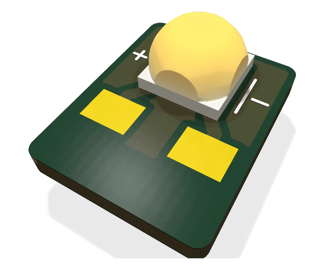
The strobe LED tab: one Cree XP-L near the top of a 7 x 8.75 mm aluminium tab with its LED facing the horizon; six in the top dome's base ring make the top strobe, two in each keel behind flush windows make the belly strobe.
- Revision
- A draft
- Sheets
- 1
- Parts
- 3
- Board
- 7 × 8.8 mm
- Copper layers
- 2
- Footprints
- 3
- Location
- aircraft
- Bus
- none: a two-wire LED string to the lights node's strobe channel
- Status
- Rev A draft: DRC clean (2026-10-10), not ordered
What it does
It holds one bare white LED with its axis horizontal. The anti-collision strobe is a low clear dome, about 40 mm across and 10 mm proud of the skin, and six of these tabs stand in a ring inside it at 60 degrees, each LED 4.25 mm above the skin plane facing outward. No lens: a bare XP-L’s 125 degree beam, six of them at 60 degrees, gives a minimum of about 532 cd at the horizon at 2 A through the clear dome (138 cd effective at the node’s 70 ms flash, against th-avionics’ 100 cd minimum; docs/strobe_intensity.py in the EDA repo). The dome has to be optically clear; a translucent printed one diffuses the light upward and fails the minimum.
Where it sits
Six in the top dome on the Bay roof behind the Q43 crest: each tab’s bottom 2 mm is a bare foot in a 1.1 mm slot in the opaque base ring, epoxied to the aluminium base disc that carries the heat into the skin; the wire pads sit just above the ring, and 24 AWG jumpers link the six in series to the node’s J10 pads. Six in the keels since 2026-10-11 (Ryan; the belly dome on the payload cover is withdrawn): three per keel B mount in a small root boss at the keel’s aft edge, two forward behind clear windows faced square to their LED axes, turned about 45 degrees forward of the face normal, so the keels cover the forward horizon the roof and the Q43 crest shade from the top dome (th-avionics), and one facing straight aft behind its own window in the boss’s aft closure, which closes the aft-below sector. Each tab hangs head-down from a 1 mm aluminium strip that runs from under its foot, through a slot in the motor pad, to lie under the lift motor’s base, so the motor is the heat sink (th-blender 5e789f7; about 0.33 W a tab at 2.2 A, with a tab about 16 K over the motor base and a stopped motor about 30 K over still air, estimates to be checked on the bench). The six are one series loop across the belly on the node’s second strobe channel (J11, 2.2 A, about 19.5 V), flashing together and alternating with the top dome, which runs at 2.0 A.
Main parts
| Part | Function |
|---|---|
| Cree XLamp XP-L (XPLAWT, cool white) | The LED, on Cree’s recommended land, centred 6.25 mm up the tab |
| The board | 7.0 x 8.75 x 1.0 mm single-layer aluminium, the LED’s thermal pad poured over the face above the foot |
Connections
| Pad | What |
|---|---|
| + | LED anode, 2.0 x 1.5 mm wire pad 2.3 to 3.8 mm up the tab, left |
| - | LED cathode, the same, right |
Status
Rev A draft, 2026-10-10 (EDA d672e96): generated from gen/design.py and gen/layout.py, ERC 0, DRC 0 errors and 0 warnings at every severity with parity; STEP and render in the repo for th-blender’s dome. Fourteen pieces per order (twelve fitted, two spare) as bare boards from JLCPCB’s aluminium service; the LED and wires are hand-fitted. Replaces the withdrawn hexagonal pod’s facet board. The keel arrangement is th-blender’s to draw; the per-LED intensity against angle for th-avionics’ coverage check follows the window aims.
Schematic and layout
The 3D board loads when you open this view.
Files
From the EDA repository at revision b201257 (2026-10-12). Open the files in KiCad 10 or later.
Comments
Comment on the whole page here, or on one section or step with the button beside it.