
Beacon block board: power-rails
Boards / beacon nets cut at the block boundary by tools/blockgen.py; bench header pins are the only addition
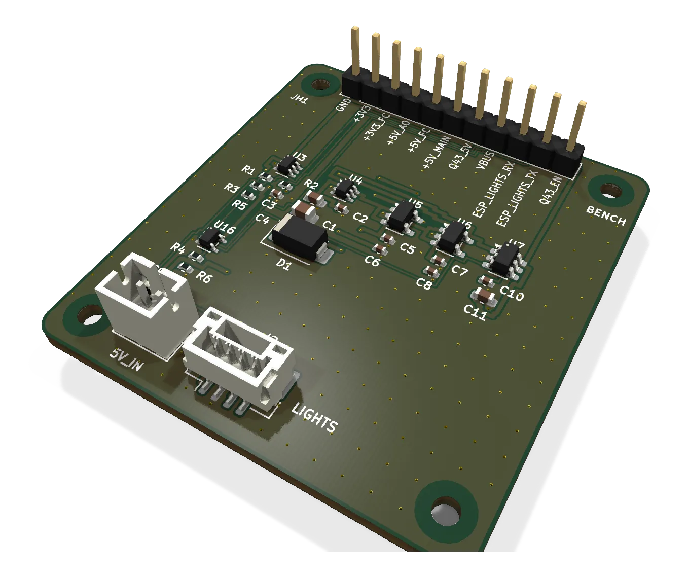
The beacon's power input and rails on their own board: the two ideal diodes that join main 5 V and the lighting battery's 5 V, the two 3.3 V regulators and the Q43's load switch, for bench proof of the hand-over before the beacon is built.
- Revision
- A
- Sheets
- 1
- Parts
- 27
- Board
- 42 × 45 mm
- Copper layers
- 2
- Footprints
- 31
- Location
- bench
- Bus
- none: the beacon's 5V_IN and LIGHTS connectors on one side, an 11-pin header for the rails and the ESP32 signals
- Status
- Rev A draft: routed, DRC clean (2026-10-10), not ordered
What it does
A bench board carrying the beacon’s power and rails blocks: the two LM66100 ideal diodes that OR the main 5 V and the lights node’s +5V_LIGHT into the always-on rail, the AP2112K that makes 3.3 V for the ESP32 and the radios, the second AP2112K that makes the flight-controller-side 3.3 V from the FC port’s 5 V, and the TPS22917 load switch through which the ESP32 can drop the Q43 to save the lighting battery in lost mode. The thing to see on the bench is the hand-over: pull main 5 V and the always-on rail must not dip; restore it and nothing back-feeds the lights node.
Like the other block boards it is cut from the beacon’s design data by a tool and checked net by net against the beacon, so it is the beacon’s own power path on a board of its own.
Where it sits
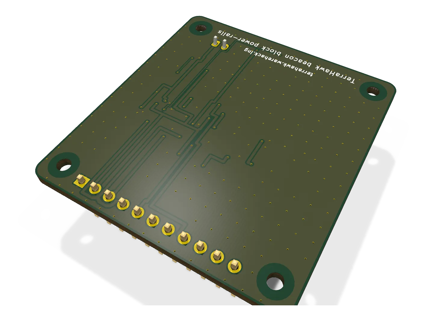
On the bench. The beacon’s 5V_IN (PH-2) and LIGHTS (GH-4) connectors are on the board, so a bench supply and a lights node (or a second supply standing in for it) plug in as they would on the aircraft; the rails and the ESP32’s control lines come to an 11-pin 2.54 mm header. 42 x 45 mm, two layers, every part on the top face.
Main parts
| Part | Function |
|---|---|
| 2 x LM66100 | Ideal-diode OR of main 5 V and +5V_LIGHT into +5V_AO, the always-on rail |
| AP2112K-3.3 (x2) | 3.3 V for the always-on side; 3.3 V for the FC side from the FC port’s 5 V |
| TPS22917 | Load switch for the Q43’s 5 V, on by default, dropped by the ESP32 in lost mode |
| J1, J2 | The beacon’s 5V_IN and LIGHTS connectors, same parts and pin order |
Connections
| Pin | Net | Stands in for, on the beacon |
|---|---|---|
| JH1-1 | GND | ground |
| JH1-2 | +3V3 | the always-on 3.3 V rail, out to the bench (the ESP32 and radios’ supply) |
| JH1-3 | +3V3_FC | the FC-side 3.3 V, out (the isolators’ FC side) |
| JH1-4 | +5V_AO | the always-on 5 V rail, out (the piezo) |
| JH1-5 | +5V_FC | the FC port’s 5 V, in from the bench (what GPS1 or TELEM2 would bring) |
| JH1-6 | +5V_MAIN | the main 5 V as sensed by the opto |
| JH1-7 | Q43_5V | the switched 5 V for the Q43, out |
| JH1-8 | VBUS | USB 5 V, in, for the USB-powered bench case |
| JH1-9, 10 | ESP_LIGHTS_RX, ESP_LIGHTS_TX | the lights-node UART, through to the header |
| JH1-11 | Q43_EN | the ESP32’s load-switch control, in |
Status
Rev A draft, 2026-10-10 (EDA 8a289ae): generated by tools/blockgen.py beacon power+rails, 17 nets, ERC clean apart from the same regulator-output tie the beacon’s own ERC waives, routed to 0 open, DRC 0 errors and 0 warnings, every net a subset of the beacon’s. Not ordered. Bench test: the hand-over between main 5 V and +5V_LIGHT with a scope on +5V_AO, the Q43 switch under the ESP32’s control, and the load each regulator carries against its rating.
Schematic and layout
The 3D board loads when you open this view.
Files
From the EDA repository at revision b201257 (2026-10-12). Open the files in KiCad 10 or later.
Comments
Comment on the whole page here, or on one section or step with the button beside it.